EP0940637A2 - Heat generating installation - Google Patents
Heat generating installation Download PDFInfo
- Publication number
- EP0940637A2 EP0940637A2 EP99103647A EP99103647A EP0940637A2 EP 0940637 A2 EP0940637 A2 EP 0940637A2 EP 99103647 A EP99103647 A EP 99103647A EP 99103647 A EP99103647 A EP 99103647A EP 0940637 A2 EP0940637 A2 EP 0940637A2
- Authority
- EP
- European Patent Office
- Prior art keywords
- energy
- housing
- heat
- heat exchange
- exchange device
- Prior art date
- Legal status (The legal status is an assumption and is not a legal conclusion. Google has not performed a legal analysis and makes no representation as to the accuracy of the status listed.)
- Granted
Links
Images


Classifications
-
- F—MECHANICAL ENGINEERING; LIGHTING; HEATING; WEAPONS; BLASTING
- F02—COMBUSTION ENGINES; HOT-GAS OR COMBUSTION-PRODUCT ENGINE PLANTS
- F02B—INTERNAL-COMBUSTION PISTON ENGINES; COMBUSTION ENGINES IN GENERAL
- F02B63/00—Adaptations of engines for driving pumps, hand-held tools or electric generators; Portable combinations of engines with engine-driven devices
- F02B63/04—Adaptations of engines for driving pumps, hand-held tools or electric generators; Portable combinations of engines with engine-driven devices for electric generators
-
- F—MECHANICAL ENGINEERING; LIGHTING; HEATING; WEAPONS; BLASTING
- F01—MACHINES OR ENGINES IN GENERAL; ENGINE PLANTS IN GENERAL; STEAM ENGINES
- F01K—STEAM ENGINE PLANTS; STEAM ACCUMULATORS; ENGINE PLANTS NOT OTHERWISE PROVIDED FOR; ENGINES USING SPECIAL WORKING FLUIDS OR CYCLES
- F01K23/00—Plants characterised by more than one engine delivering power external to the plant, the engines being driven by different fluids
- F01K23/02—Plants characterised by more than one engine delivering power external to the plant, the engines being driven by different fluids the engine cycles being thermally coupled
- F01K23/06—Plants characterised by more than one engine delivering power external to the plant, the engines being driven by different fluids the engine cycles being thermally coupled combustion heat from one cycle heating the fluid in another cycle
- F01K23/065—Plants characterised by more than one engine delivering power external to the plant, the engines being driven by different fluids the engine cycles being thermally coupled combustion heat from one cycle heating the fluid in another cycle the combustion taking place in an internal combustion piston engine, e.g. a diesel engine
-
- F—MECHANICAL ENGINEERING; LIGHTING; HEATING; WEAPONS; BLASTING
- F02—COMBUSTION ENGINES; HOT-GAS OR COMBUSTION-PRODUCT ENGINE PLANTS
- F02B—INTERNAL-COMBUSTION PISTON ENGINES; COMBUSTION ENGINES IN GENERAL
- F02B77/00—Component parts, details or accessories, not otherwise provided for
- F02B77/11—Thermal or acoustic insulation
- F02B77/13—Acoustic insulation
-
- F—MECHANICAL ENGINEERING; LIGHTING; HEATING; WEAPONS; BLASTING
- F02—COMBUSTION ENGINES; HOT-GAS OR COMBUSTION-PRODUCT ENGINE PLANTS
- F02G—HOT GAS OR COMBUSTION-PRODUCT POSITIVE-DISPLACEMENT ENGINE PLANTS; USE OF WASTE HEAT OF COMBUSTION ENGINES; NOT OTHERWISE PROVIDED FOR
- F02G5/00—Profiting from waste heat of combustion engines, not otherwise provided for
-
- F—MECHANICAL ENGINEERING; LIGHTING; HEATING; WEAPONS; BLASTING
- F24—HEATING; RANGES; VENTILATING
- F24D—DOMESTIC- OR SPACE-HEATING SYSTEMS, e.g. CENTRAL HEATING SYSTEMS; DOMESTIC HOT-WATER SUPPLY SYSTEMS; ELEMENTS OR COMPONENTS THEREFOR
- F24D2200/00—Heat sources or energy sources
- F24D2200/16—Waste heat
- F24D2200/26—Internal combustion engine
-
- Y—GENERAL TAGGING OF NEW TECHNOLOGICAL DEVELOPMENTS; GENERAL TAGGING OF CROSS-SECTIONAL TECHNOLOGIES SPANNING OVER SEVERAL SECTIONS OF THE IPC; TECHNICAL SUBJECTS COVERED BY FORMER USPC CROSS-REFERENCE ART COLLECTIONS [XRACs] AND DIGESTS
- Y02—TECHNOLOGIES OR APPLICATIONS FOR MITIGATION OR ADAPTATION AGAINST CLIMATE CHANGE
- Y02E—REDUCTION OF GREENHOUSE GAS [GHG] EMISSIONS, RELATED TO ENERGY GENERATION, TRANSMISSION OR DISTRIBUTION
- Y02E20/00—Combustion technologies with mitigation potential
- Y02E20/14—Combined heat and power generation [CHP]
-
- Y—GENERAL TAGGING OF NEW TECHNOLOGICAL DEVELOPMENTS; GENERAL TAGGING OF CROSS-SECTIONAL TECHNOLOGIES SPANNING OVER SEVERAL SECTIONS OF THE IPC; TECHNICAL SUBJECTS COVERED BY FORMER USPC CROSS-REFERENCE ART COLLECTIONS [XRACs] AND DIGESTS
- Y02—TECHNOLOGIES OR APPLICATIONS FOR MITIGATION OR ADAPTATION AGAINST CLIMATE CHANGE
- Y02T—CLIMATE CHANGE MITIGATION TECHNOLOGIES RELATED TO TRANSPORTATION
- Y02T10/00—Road transport of goods or passengers
- Y02T10/10—Internal combustion engine [ICE] based vehicles
- Y02T10/12—Improving ICE efficiencies
Definitions
- the present invention relates to a plant for generating of energy, especially energy compact system with at least one drive unit at least one Generator is assigned.
- Such drive units are in the most varied of forms and Execution known and used on the market. she primarily serve to generate energy, especially electricity. They essentially stand out in that they can be used flexibly and independently are.
- a disadvantage of such devices is that conventional Drive units have a high energy loss because they give off unused heat. Furthermore, they are not suitable to complete a household with everyone required energies in different forms such as To supply electricity, heat etc.
- the present invention is based on the object Creation of the above Kind of creating a separate and permits complete energy supply, for example for a house, such a customer completely independent of external energy suppliers, houses or apartments with Can supply energy.
- the drive unit leads to the solution of this task to use waste heat in a sound and / or heat-insulating housing is arranged.
- the present invention allows that of the Drive unit emitted heat and the Drive unit emitted hot exhaust gases in at least a heat exchanger can be evaluated.
- Various heat exchangers can be provided to the To use waste heat from such a drive unit.
- a heat exchanger is preferably air and gas-permeable register formed, which of hot Air or hot exhaust gases from the drive unit is flowable. This will, for example, warm water for a heating boiler or heating circuit of a house or warmed up for a domestic water boiler in a residential building.
- the current generated by the generator controlled by an electric control, a heat pump or an electric heater. This leaves the desired hot water temperature or temperature regulate and control the heating circuit in the customer precisely.
- Another peculiarity of the present invention is if there is additional external or internal in the housing Energy storage, for example in the form of batteries, is provided are. Then, with lower loads, the operation of the Drive unit are dispensed with, the Load recipients are supplied via the energy storage.
- Energy storage for example in the form of batteries
- Another particularly advantageous embodiment of the Invention shows an additional heat exchange device, what warm air for heating rooms, especially about a ventilation system that brings buildings into.
- This Heat exchange device is air through an inlet port supplied and heated air via an outlet in supplied a ventilation system. From there you can Most rooms are heated.
- the present invention is a system in particular created an energy compact system, which independent and independent of external and external Energize a house or living space with energy can.
- the customers such as process water, boilers or Heating circuit boiler is not in operation at night and is in only slightly consumes energy in a household, so the drive unit switches off automatically.
- the remaining energy requirement is via the energy storage especially covered batteries.
- the present Invention is about a heat exchange device as it is described above, energy, for example Block heat and power plant withdrawn.
- the heat exchange device is also over a medium, especially water operated and carries heat to a customer, in particular Boiler too.
- This boiler, or at least part of it can preferably via external energy, preferably by means of of a burner, to be strongly heated so that in the customer or boiler steam generation takes place.
- This Overpressure, especially this water vapor is in one energy converter assigned to the customer, in particular Steam generator converted to electricity. This allows the Waste heat, for example, from a combined heat and power plant for direct Electricity generation can be used, which is its efficiency significantly increases.
- the steam turbines used to generate electricity can only be done with minor, additional Energy expenditure can be operated. It's just that Temperature difference between the temperature of the waste heat and the temperature required to generate steam, required.
- the condensate, which is on the steam generator drops and its temperature approximately at 90 ° C, the customer, especially the boiler fed again.
- a system R has Generation of energy, in particular compact energy system, a housing 1, which is preferably sound and is designed to be heat-insulating.
- the housing is preferred 1 airtight design.
- a drive unit 2 is provided, which via a connecting line 3 indicated here by dashed lines communicates with an energy reservoir 4. in the In the present exemplary embodiment, the energy reservoir 4 arranged externally to the housing 1. However, it should also do that be thought of the energy reservoir 4 in the housing 1 integrate. It provides the necessary energy for that Drive unit 2.
- This is petrol, diesel, rapeseed oil, Bio oil, from different plants, or other Organic substances thought.
- the drive unit 2 is connected to a generator 5.
- This generator 5 is connected to a control device 6 Connection, which is only indicated here via lines 7.1, 7.2 distributes and regulates the electricity.
- the Line 7.1 leads to any load consumers, for example one House. If only light loads are frozen at night, for example, the control device 6 switches to its own Energy storage 8 um, which are arranged in the housing 1.
- the energy stores 8 are preferably close to one Housing bottom 9 arranged, and are on a partition 10 foreclosed.
- the system R delivers, for example, at night without the generator 5 and thus the drive unit 2 can be operated need permanent energy from the energy storage 8.
- the Control device 6 takes over the necessary for this Control and regulation. Falls a certain Voltage potential of the energy storage 8, so automatically via the control device 6 Drive unit 2 turns on and loads the preferably Energy storage 8 arranged internally in the housing 1.
- generator 5 delivers at higher loads enough electricity to power all load recipients, for example Provide enough energy for a family home.
- Another special feature of the present invention is that the waste heat from the drive unit 2 is used. Due to the heat-insulated housing 1 inside generates high heat. This heat is over Heat exchange devices 11.1, 11.2 used.
- the heat exchange device 11.1 is preferably air and exhaust gas permeable register formed. This is preferably arranged above the drive unit 2, through which the heated air in the housing 1 to the outside can leak.
- the heat exchange device 11.1 is after an exhaust air intake element 12 is assigned to the outside.
- the Exhaust air intake element 12 leads directly into the open and transfers the heat or exhaust air from the drive unit 2 an exhaust air duct 13.
- Fresh air is supplied to the Inlet 19 assigned to housing 1. This can also be the case preheated room air or fresh air.
- the heat exchange device 11.1 is above heat pipes 14.1, 14.2 with at least one customer 15.1, 15.2 in Connection. Corresponding adjustable and not detailed here numbered valves and heat pumps regulate the volume flow when heat exchange of the heat exchange device 11.1.
- the Customers 15.1, 15.2 can, for example, boilers for domestic water or boiler for a heating circuit, as indicated here it's his.
- electrical in the boilers Heating elements 16.1, 16.2 may be provided, which over the Energy storage 8 or directly via the generator 5 are operable.
- Another heat exchanger 11.2 is preferably on the side provided in the housing 1. This essentially serves as shown in particular in Figure 2 for Heating air, passing the air through one Inlet connector 20 flows into the housing 1 through Heat exchange device 11.2 in direct current or Countercurrent process transported and over a Outlet connector 17 is supplied to a ventilation system 18.
- the outlet connector 17 can, for example, directly into a room flow into. Individual ventilation can be done via the ventilation system 18 Rooms, which are connected to it, are controllably heated become.
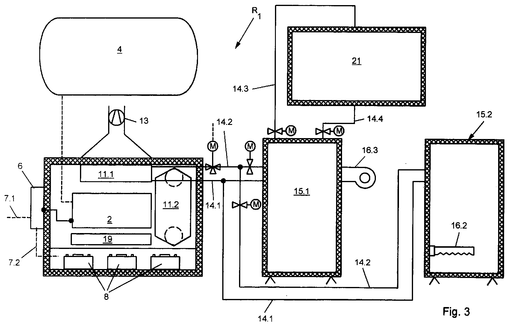
- FIG. 3 a further system R 1 is shown, which essentially contains the components shown in FIGS. 1 and 2.
- the difference here is that, instead of the heating element 16.1, a heating element 16.3 is connected externally, for example as a combustion device, to the consumer 15.1.
- the consumer 15.1 can be heated via the external heating element 16.3.
- Waste heat preheated water in the customer 15.1, which formed as a boiler in the present embodiment is.
- the water heated by waste heat in the customer 15.1 can be further heated by the heating element 16.3. This is then a further heat pipes 14.3, 14.4 Energy converter 21 supplied.
- the temperature in the customer 15.1, in particular boiler heated in such a way that it is used to generate energy, in particular electricity generation in the energy converter 21, steam generator is particularly suitable.
- the waste heat which is obtained, for example, from combined heat and power plants is, the water in the customer 15.1 warms up to about 70 to 80 ° C.
- Over the burner or over the heating element 16.3 must only the temperature difference in the form of energy are supplied, which for the steam generator or Energy converter 21 is required.
- the temperature in the customer 15.1 only increases Steam generation temperature is heated and then the Steam the steam generator to generate energy fed.
- the condensate coming from the steam generator excretes, has a temperature of about 90 ° C and can Via heat conduction 14.4 directly to the customer 15.1 be fed. This creates a circulation, whereby only the temperature difference between the Steam generation temperature and the temperature in the customer 15.1 must be supplied by the heating element 16.3.
- the heat exchange device 11.1 is assigned to a combined heat and power plant.
- This waste heat by means of which conventional cogeneration plants were used to heat apartments or other buildings, can now be used directly to generate electricity. This significantly increases the efficiency of combined heat and power plants. The large temperature losses through long-distance lines and the like can be eliminated.
- Item number list 1 casing 34 67 2nd Drive unit 35 68 3rd Connecting line 36 69 4th Energy reservoir 37 70 5 generator 38 71 6 Control device 39 72 7 management 40 73 8th Energy storage 41 74 9 Case back 42 75 10th partition wall 43 76 11 Heat exchange device 44 77 12th Exhaust air intake element 45 78 13 Exhaust duct 46 79 14 Heat conduction 47 R investment 15 customer 48 16 Heating element 49 17th Outlet connector 50 18th Ventilation system 51 19th inlet 52 20th Inlet connector 53 21 Energy converter 54 22 55 23 56 24th 57 25th 58 26 59 27 60 28 61 29 62 30th 63 31 64 32 65 33 66
Landscapes
- Engineering & Computer Science (AREA)
- Chemical & Material Sciences (AREA)
- Combustion & Propulsion (AREA)
- Mechanical Engineering (AREA)
- General Engineering & Computer Science (AREA)
- Physics & Mathematics (AREA)
- Acoustics & Sound (AREA)
- Engine Equipment That Uses Special Cycles (AREA)
- Heat-Pump Type And Storage Water Heaters (AREA)
- Wind Motors (AREA)
Abstract
Bei einer Anlage zum Erzeugen von Energie, insbesondere
Energie-Kompakt-Anlage mit zumindest einem Antriebsaggregat
(2) dem wenigstens ein Generator (5) zugeordnet ist, ist
das Antriebsaggregat (2) zur Nutzung von Abwärme in einem
schall- und/oder wärmeisolierendem Gehäuse (1) angeordnet.
Description
Die vorliegende Erfindung betrifft eine Anlage zum Erzeugen von Energie, insbesondere Energie-Kompakt-Anlage mit zumindest einem Antriebsaggregat dem Wenigstens ein Generator zugeordnet ist.The present invention relates to a plant for generating of energy, especially energy compact system with at least one drive unit at least one Generator is assigned.
Derartige Antriebsaggregate sind in vielfältigster Form und Ausführung auf dem Markt bekannt und gebräuchlich. Sie dienen in erster Linie zum Erzeugen von Energie, insbesondere Strom. Sie zeichnen sich im wesentlichen dadurch aus, dass sie flexibel und unabhängig einzusetzen sind.Such drive units are in the most varied of forms and Execution known and used on the market. she primarily serve to generate energy, especially electricity. They essentially stand out in that they can be used flexibly and independently are.
Nachteilig an derartigen Geräten ist, dass herkömmliche Antriebsaggregate einen hohen Energieverlust aufweisen, da sie ungenutzte Wärme abgeben. Ferner sind sie nicht geeignet, um einen Haushalt vollständig mit allen erforderlichen Energien in unterschiedlicher Form wie bspw. Strom, Wärme etc. zu versorgen.A disadvantage of such devices is that conventional Drive units have a high energy loss because they give off unused heat. Furthermore, they are not suitable to complete a household with everyone required energies in different forms such as To supply electricity, heat etc.
Der vorliegenden Erfindung liegt die Aufgabe zugrunde eine Anlage der o.g. Art zu schaffen, welche eine separate und vollständige Energieversorgung bspw. für ein Haus zulässt, wobei ein derartiger Abnehmer völlig unabhängig von externen Energieversorgern, Wohnhäuser oder Wohnungen mit Energie versorgen kann.The present invention is based on the object Creation of the above Kind of creating a separate and permits complete energy supply, for example for a house, such a customer completely independent of external energy suppliers, houses or apartments with Can supply energy.
Ferner sollen dabei Energiekosten reduziert und bedarfsgerecht verwendet werden. Zudem soll eine derartige Anlage universell einsetzbar und in herkömmliche Wohnhäuser nachrüstbar sein.Furthermore, energy costs should be reduced and can be used as required. In addition, such System can be used universally and in conventional residential buildings can be retrofitted.
Zur Lösung dieser Aufgabe führt, dass das Antriebsaggregat zur Nutzung von Abwärme in einem schall- und/oder wärmeisolierendem Gehäuse angeordnet ist.The drive unit leads to the solution of this task to use waste heat in a sound and / or heat-insulating housing is arranged.
Die vorliegende Erfindung gestattet, dass die von dem Antriebsaggregat abgegebene Wärme und die vom Antriebsaggregat abgegebenen heissen Abgase in zumindest einem Wärmetauscher ausgewertet werden. In dem Gehäuse können verschiedenste Wärmetauscher vorgesehen sein, um die Abwärme eines derartigen Antriebsaggregates zu nutzen.The present invention allows that of the Drive unit emitted heat and the Drive unit emitted hot exhaust gases in at least a heat exchanger can be evaluated. In the case Various heat exchangers can be provided to the To use waste heat from such a drive unit.
Ein Wärmetauscher ist vorzugsweise als luft und gasdurchlässiges Register ausgebildet, welches von heisser Luft bzw. auch von heissen Abgasen des Antriebsaggregates durchströmbar ist. Hierdurch wird bspw. warmes Wasser für einen Heizboiler bzw. Heizkreislauf eines Wohnhauses oder für einen Brauchwasserboiler in einem Wohnhaus aufgewärmt. Zusätzlich kann der durch den Generator erzeugte Strom, gesteuert über eine elektrische Steuerung, eine Wärmepumpe oder eine elektrische Heizung, betreiben. Hierdurch lässt sich die gewünschte Brauchswassertemperatur oder Temperatur des Heizkreislaufes im Abnehmer exakt regeln und steuern. A heat exchanger is preferably air and gas-permeable register formed, which of hot Air or hot exhaust gases from the drive unit is flowable. This will, for example, warm water for a heating boiler or heating circuit of a house or warmed up for a domestic water boiler in a residential building. In addition, the current generated by the generator, controlled by an electric control, a heat pump or an electric heater. This leaves the desired hot water temperature or temperature regulate and control the heating circuit in the customer precisely.
Eine weitere Besonderheit der vorliegenden Erfindung ist dann gegeben, wenn zusätzlich extern oder intern im Gehäuse Energiespeicher, bspw. in Form von Batterien, vorgesehen sind. Dann kann bei geringeren Lasten auf den Betrieb des Antriebsaggregates verzichtet werden, wobei die Lastabnehmer über die Energiespeicher versorgt werden.Another peculiarity of the present invention is if there is additional external or internal in the housing Energy storage, for example in the form of batteries, is provided are. Then, with lower loads, the operation of the Drive unit are dispensed with, the Load recipients are supplied via the energy storage.
Eine weitere besonders vorteilhafte Ausgestaltung der Erfindung zeigt eine zusätzliche Wärmetauscheinrichtung, welche Warmluft zum Beheizen von Räumen, insbesondere über ein Belüftungssystem, in das Gebäude einbringt. Dieser Wärmetauscheinrichtung wird Luft über einen Einlassstutzen zugeführt und erwärmte Luft über einen Auslassstutzen in ein Belüftungssystem zugeführt. Von dort können eine Mehrzahl von Räume beheizt werden.Another particularly advantageous embodiment of the Invention shows an additional heat exchange device, what warm air for heating rooms, especially about a ventilation system that brings buildings into. This Heat exchange device is air through an inlet port supplied and heated air via an outlet in supplied a ventilation system. From there you can Most rooms are heated.
Insgesamt ist mit der vorliegendnen Erfindung eine Anlage, insbesondere eine Energie-Kompakt-Anlage geschaffen, welche selbstständig und unabhängig von fremden und externen Energien ein Haus oder ein Wohnraum mit Energie versorgen kann. Sind die Abnehmer wie bspw. Brauchwasser, Boiler oder Heizkreislaufboiler nachts nicht im Betrieb und wird in einem Haushalt nur geringfügig Energie verbraucht, so schaltet sich automatisch das Antriebsaggregat ab. Der übrige Energiebedarf wird über die Energiespeicher insbesondere Batterien abgedeckt.Overall, the present invention is a system in particular created an energy compact system, which independent and independent of external and external Energize a house or living space with energy can. Are the customers such as process water, boilers or Heating circuit boiler is not in operation at night and is in only slightly consumes energy in a household, so the drive unit switches off automatically. Of the the remaining energy requirement is via the energy storage especially covered batteries.
Ferner entfallen bei einer derartigen Anlage herkömmliche Schornsteinfegerkosten sowie Anschlussgebühren der Energieversorger pro Einfamilienhaus, die in etwa bei DM 4.000,-- bis DM 6.000,-- liegen. Es können herkömmliche teure Heizkörper, Heizkessel oder Stromversorgungsanlagen etc. entfallen.Furthermore, conventional systems are not required in such a system Chimney sweep costs and connection fees for energy suppliers per family house, which is approximately at DM 4,000 to DM 6,000. It can be conventional expensive radiators, boilers or power supply systems etc. omitted.
Durch die Verwendung von Wohnraumbe- und entlüftungsanlagen wird zugleich der Wohnung zusätzlich die notwendige Frischluft zugeführt. Ferner können durch die Verwendung von Biotreibstoffen als Energielieferanten für das Antriebsaggregat sehr umweltfreundlich und vollständige Energieversorgungen auf engstem Raum preisgünstig ausgenutzt werden.Through the use of living space ventilation and ventilation systems at the same time the apartment becomes the necessary one Fresh air supplied. Furthermore, through the use of biofuels as energy suppliers for the Power pack very environmentally friendly and complete Inexpensive energy supplies in the smallest of spaces be exploited.
In einem weiteren Ausführungsbeispiel der vorliegenden Erfindung wird über eine Wärmetauscheinrichtung, wie sie oben beschrieben ist, Energie bspw. einem Blockheizkraftwerk entzogen. Die Wärmetauscheinrichtung wird ebenfalls über ein Medium, insbesondere Wasser betrieben und führt Wärme einem Abnehmer, insbesondere Boiler zu. Dieser Boiler oder zumindest ein Teil von ihm kann über vorzugsweise externe Energie, bevorzugt mittels eines Brenners, stark erhitzt werden, so dass im Abnehmer bzw. Boiler eine Dampferzeugung stattfindet. Dieser Überdruck, insbesondere dieser Wasserdampf, wird in einem dem Abnehmer zugeordneten Energiewandler, insbesondere Dampfgenerator zu Strom umgewandelt. Hierdurch kann die Abwärme bspw. eines Blockheizkraftwerkes zur direkten Stromerzeugung genutzt werden, was dessen Wirkungsgrad wesentlich steigert.In another embodiment of the present Invention is about a heat exchange device as it is described above, energy, for example Block heat and power plant withdrawn. The heat exchange device is also over a medium, especially water operated and carries heat to a customer, in particular Boiler too. This boiler, or at least part of it can preferably via external energy, preferably by means of of a burner, to be strongly heated so that in the customer or boiler steam generation takes place. This Overpressure, especially this water vapor, is in one energy converter assigned to the customer, in particular Steam generator converted to electricity. This allows the Waste heat, for example, from a combined heat and power plant for direct Electricity generation can be used, which is its efficiency significantly increases.
Die Dampfturbinen, welche zur Stromerzeugung eingesetzt werden, können nur mit geringfügigem, zusätzlichen Energieaufwand betrieben werden. Es ist lediglich die Temperaturdifferenz zwischen der Temperatur der Abwärme und der Temperatur, welche zur Dampferzeugung notwendig ist, erforderlich. Ebenfalls wird das Kondensat, welches an dem Dampfgenerator abfällt und dessen Temperatur in etwa bei 90°C liegt, dem Abnehmer, insbesondere dem Boiler wieder zugeführt.The steam turbines used to generate electricity can only be done with minor, additional Energy expenditure can be operated. It's just that Temperature difference between the temperature of the waste heat and the temperature required to generate steam, required. The condensate, which is on the steam generator drops and its temperature approximately at 90 ° C, the customer, especially the boiler fed again.
Hierdurch wird die Abwärme eines derartigen Blockheizkraftwerkes, welches bspw. nach herkömmlicher Art durch fossile Brennstoffe, wie Gas, Öl, Biobrennstoffe, Holzschnipsel, Altöl oder anderen fossilen Brennstoffen betrieben wird, ausgenutzt.As a result, the waste heat from such Combined heat and power plant, which, for example, in the conventional way through fossil fuels such as gas, oil, biofuels, Wood chips, waste oil or other fossil fuels is operated, exploited.
Ferner müssen derartige Blockheizkraftwerke gekühlt werden, wozu frisches Brauchwasser verwendet wird. Dieses wird dem Kreislauf zugeführt. Es erwärmt sich und muss dann über Kühlflächen abgeleitet und luftgekühlt werden. Hierzu können Düsen oder Ventilatoren vorgesehen sein, welche die Umgebungsluft direkt unter der warmwasserführenden Fläche abführt, so dass das Wasser besser gekühlt werden kann. Dieses Wasser kann über Becken, Erdbecken oder Erdauffangbehälter gesammelt werden. Diese sind in gewissen Abständen aneinandergereiht, um die Abkühlung von einem Becken zum nächsten bis zur gewünschten Wassertemperatur zu gewährleisten. Aus dem letzten, jeweils erkaltetem Becken, wird das kalte Wasser zur Kühlung der Heizkraftwerke erneut in dessen Kreislauf gebracht. Zudem kann das vollständige Wasserreservoir bspw. unter der Verwendung von Regenwasser nachgefüllt werden, damit immer genügend frisches Wasser im Umlauf ist. Entsprechende Überläufe regeln das Wasserreservoir. Furthermore, such cogeneration plants have to be cooled, what fresh service water is used for. This will be the Circulated. It warms up and then has to over Cooling surfaces are derived and air-cooled. For this can be provided nozzles or fans which the Ambient air directly under the hot water surface dissipates so that the water can be cooled better. This water can flow through basins, or basins Soil collection containers are collected. These are in certain Intervals lined up to cool off one Pool to the next up to the desired water temperature guarantee. From the last, cooled pool, the cold water for cooling the thermal power stations is renewed brought into its cycle. In addition, the complete Water reservoir using rainwater, for example be refilled so that there is always enough fresh water in the Is in circulation. Corresponding overflows regulate this Water reservoir.
Weitere Vorteile, Merkmale und Einzelheiten der Erfindung
ergeben sich aus der nachfolgenden Beschreibung bevorzugter
Ausführungsbeispiele sowie anhand der Zeichnung; diese
zeigt in
Gemäss Figur 1 weist eine erfindungsgemässe Anlage R zum
Erzeugen von Energie, insbesondere Energie-Kompakt-Anlage,
ein Gehäuse 1 auf, welches vorzugsweise schall- und
wärmeisolierend ausgebildet ist. Bevorzugt ist das Gehäuse
1 luftundurchlässig ausgebildet. In etwa mittig des
Gehäuses 1 ist ein Antriebsaggregat 2 vorgesehen, welches
über eine hier gestrichelt angedeutete Verbindungsleitung 3
mit einem Energiereservoir 4 in Verbindung steht. Im
vorliegendem Ausführungsbeispiel ist das Energiereservoir 4
extern zum Gehäuse 1 angeordnet. Es soll jedoch auch daran
gedacht sein, das Energiereservoir 4 in das Gehäuse 1 zu
intergrieren. Es liefert die notwendige Energie für das
Antriebsaggregat 2. Hierbei ist an Benzin, Diesel, Rapsöl,
Bioöl, aus unterschiedlichen Pflanzen, oder sonstigen
Biostoffen gedacht.According to FIG. 1, a system R according to the invention has
Generation of energy, in particular compact energy system,
a housing 1, which is preferably sound and
is designed to be heat-insulating. The housing is preferred
1 airtight design. In the middle of the
Housing 1, a
Das Antriebsaggregat 2 ist mit einem Generator 5 verbunden.
Dieser Generator 5 steht mit einer Steuereinrichtung 6 in
Verbindung, welche über hier nur angedeutete Leitungen 7.1,
7.2 die Verteilung und Regelung des Stromes vornimmt. Die
Leitung 7.1 führt zu beliebigen Lastabnehmern bspw. eines
Hauses. Wird nur geringe Last bspw. in der Nacht erfrodert,
so schaltet die Steuereinrichtung 6 auf eigene
Energiespeicher 8 um, welche im Gehäuse 1 angeordnet sind.
Vorzugsweise sind die Energiespeicher 8 nahe eines
Gehäusebodens 9 angeordnet, und werden über eine Trennwand
10 abgeschottet.The
Die Anlage R liefert bspw. nachts ohne dass der Generator 5
und damit auch das Antriebsaggregat 2 betrieben werden
müssen permanent Energie aus dem Energiespeicher 8. Die
Steuereinrichtung 6 übernimmt die hierzu notwendige
Steuerung und Regelung. Fällt ein bestimmtes
Spannungspotential der Energiespeicher 8 ab, so wird
automatisch über die Steuereinrichtung 6 das
Antriebsaggregat 2 einschaltet und lädt die vorzugsweise
intern im Gehäuse 1 angeordneten Energiespeicher 8 auf.
Gleichzeitig liefert bei höheren Lasten der Generator 5
genügend Strom, um alle Lastabnehmer bspw. eines
Einfamilienhauses ausreichend mit Energie zu versorgen.The system R delivers, for example, at night without the
Eine weitere Besonderheit der vorliegenden Erfindung ist,
dass die Abwärme des Antriebsaggregates 2 genutzt wird.
Durch das wärmeisolierte Gehäuse 1 wird im Inneren eine
hohe Warme erzeugt. Diese Wärme wird über
Wärmetauscheinrichtungen 11.1, 11.2 genutzt.Another special feature of the present invention is
that the waste heat from the
Die Wärmetauscheinrichtung 11.1 ist vorzugsweise als luft- und
abgasdurchlässiges Register ausgebildet. Dieses ist
bevorzugt oberhalb des Antriebsaggregates 2 angeordnet,
durch welches die erwärmte Luft im Gehäuse 1 nach aussen
austreten kann. Der Wärmetauscheinrichtung 11.1 ist nach
aussen hin ein Abluftaufnahmeelement 12 zugeordnet. Das
Abluftaufnahmeelement 12 führt unmittelbar in das Freie und
gibt die Wärme bzw. Abluft des Antriebsaggregates 2 über
einen Abluftkanal 13 ab. Frischluft wird über einen dem
Gehäuse 1 zugeordneten Einlass 19 zugeführt. Dies kann auch
vorgewärmte Raumluft oder Frischluft sein. The heat exchange device 11.1 is preferably air and
exhaust gas permeable register formed. This is
preferably arranged above the
Die Wärmetauscheinrichtung 11.1 steht über Wärmeleitungen
14.1, 14.2 mit zumindest einem Abnehmer 15.1, 15.2 in
Verbindung. Entsprechende regelbare und hier nicht näher
bezifferte Ventile und Wärmepumpen regeln den Volummenstrom
beim Wärmeaustausch der Wärmetauscheinrichtung 11.1. Die
Abnehmer 15.1, 15.2 können bspw. Boiler für Brauchswasser
oder Boiler für einen Heizkreislauf, wie es hier angedeutet
ist, sein. Zusätzlich können in den Boilern elektrische
Heizelemente 16.1, 16.2 vorgesehen sein, welche über die
Energiespeicher 8 oder direkt über den Generator 5
betreibbar sind.The heat exchange device 11.1 is above heat pipes
14.1, 14.2 with at least one customer 15.1, 15.2 in
Connection. Corresponding adjustable and not detailed here
numbered valves and heat pumps regulate the volume flow
when heat exchange of the heat exchange device 11.1. The
Customers 15.1, 15.2 can, for example, boilers for domestic water
or boiler for a heating circuit, as indicated here
it's his. In addition, electrical in the boilers
Heating elements 16.1, 16.2 may be provided, which over the
Ein weiterer Wärmetauscher 11.2 ist vorzugsweise seitlich
in dem Gehäuse 1 vorgesehen. Dieser dient im wesentlichen,
wie es insbesondere in Figur 2 dargestellt ist, zum
Erwärmen von Luft, wobei die Luft durch einen
Einlassstutzen 20 in das Gehäuse 1 einströmt, durch die
Wärmetauscheinrichtung 11.2 im Gleichstrom oder
Gegenstromverfahren weitertransportiert und über einen
Auslassstutzen 17 einem Belüftungssystem 18 zugeführt wird.
Der Auslassstutzen 17 kann bspw. direkt in einen Raum
einmünden. Über das Belüftungssystem 18 können einzelne
Räume, welche daran angeschlossen sind, regelbar beheizt
werden.Another heat exchanger 11.2 is preferably on the side
provided in the housing 1. This essentially serves
as shown in particular in Figure 2 for
Heating air, passing the air through one
Gemäss Figur 3 ist eine weitere Anlage R1 aufgezeigt, welche im wesentlichen die in den Figuren 1 und 2 aufgezeigten Bauteile beinhaltet. Unterschiedlich ist hier, dass an den Abnehmer 15.1 anstelle des Heizelementes 16.1 ein Heizelement 16.3 extern, bspw. als Brenneinrichtung anschliesst. Über das externe Heizelement 16.3 lässt sich der Abnehmer 15.1 aufheizen.According to FIG. 3, a further system R 1 is shown, which essentially contains the components shown in FIGS. 1 and 2. The difference here is that, instead of the heating element 16.1, a heating element 16.3 is connected externally, for example as a combustion device, to the consumer 15.1. The consumer 15.1 can be heated via the external heating element 16.3.
Insbesondere gelangt in diesem Ausführungsbeispiel durch Abwärme vorgewärmtes Wasser in den Abnehmer 15.1, welcher im vorliegenden Ausführungsbeispiel als Boiler ausgebildet ist. In particular, in this embodiment Waste heat preheated water in the customer 15.1, which formed as a boiler in the present embodiment is.
Das durch Abwärme erwärmte Wasser im Abnehmer 15.1 kann
durch das Heizelement 16.3 weiter erhitzt werden. Dieses
wird dann über weitere Wärmeleitungen 14.3, 14.4 einem
Energiewandler 21 zugeführt. Bevorzugt ist der
Energiewandler 21 als Dampfgenerator ausgebildet.The water heated by waste heat in the customer 15.1 can
be further heated by the heating element 16.3. This
is then a further heat pipes 14.3, 14.4
Die Temperatur im Abnehmer 15.1, insbesondere Boiler wird
derartig erhitzt, dass sie zur Energieerzeugung,
insbesondere Stromerzeugung im Energiewandler 21,
insbesondere Dampfgenerator geeignet ist.The temperature in the customer 15.1, in particular boiler
heated in such a way that it is used to generate energy,
in particular electricity generation in the
Die Abwärme, welche bspw. über Blockheizkraftwerke gewonnen
wird, erwärmt das Wasser im Abnehmer 15.1 bis etwa 70 bis
80°C. Über den Brenner bzw. über das Heizelement 16.3 muss
lediglich die Temperaturdifferenz in Form von Energie
zugeführt werden, die für den Dampfgenerator bzw.
Energiewandler 21 erforderlich ist.The waste heat, which is obtained, for example, from combined heat and power plants
is, the water in the customer 15.1 warms up to about 70 to
80 ° C. Over the burner or over the heating element 16.3 must
only the temperature difference in the form of energy
are supplied, which for the steam generator or
Daher wird die Temperatur im Abnehmer 15.1 lediglich auf Dampferzeugungstemperatur aufgeheizt und anschliessend der Wasserdampf dem Dampfgenerator zur Erzeugung von Energie zugeführt. Das Kondensat, welches aus dem Dampfgenerator ausscheidet, hat eine Temperatur von etwa 90°C und kann über die Wärmeleitung 14.4 dem Abnehmer 15.1 direkt zugeführt werden. Hierdurch entsteht ein Umlauf, wobei lediglich die Temperaturdifferenz zwischen der Dampferzeugungstemperatur und der Temperatur im Abnehmer 15.1 durch das Heizelement 16.3 zugeführt werden muss.Therefore, the temperature in the customer 15.1 only increases Steam generation temperature is heated and then the Steam the steam generator to generate energy fed. The condensate coming from the steam generator excretes, has a temperature of about 90 ° C and can Via heat conduction 14.4 directly to the customer 15.1 be fed. This creates a circulation, whereby only the temperature difference between the Steam generation temperature and the temperature in the customer 15.1 must be supplied by the heating element 16.3.
In dem Ausführungsbeispiel der vorliegenden Erfindung
gemäss Figur 3 ist die Wärmetauscheinrichtung 11.1 einem
Blockheizkraftwerk zugeordnet. Diese Abwärme, mittels
welcher bei herkömmlichen Blockheizkraftwerken eine
Beheizung von Wohnungen oder sonstigen Gebäuden vorgenommen
wurde, kann nun zur Stromerzeugung direkt verwendet werden.
Dies steigert den Wirkungsgrad von Blockheizkraftwerken
erheblich. Die grossen Temperaturverluste durch
Fernleitungen und dgl. können entfallen.
Claims (18)
dadurch gekennzeichnet,
dass das Antriebsaggregat (2) zur Nutzung von Abwärme in einem schall- und/oder wärmeisolierendem Gehäuse (1) angeordnet ist.System for generating energy, in particular an energy compact system with at least one drive unit (2) to which at least one generator (5) is assigned,
characterized,
that the drive unit (2) for utilizing waste heat is arranged in a sound and / or heat insulating housing (1).
Applications Claiming Priority (4)
| Application Number | Priority Date | Filing Date | Title |
|---|---|---|---|
| DE19809779 | 1998-03-06 | ||
| DE19809779 | 1998-03-06 | ||
| DE19829192A DE19829192B4 (en) | 1998-03-06 | 1998-06-30 | Energy compact Anlage |
| DE19829192 | 1998-06-30 |
Publications (3)
| Publication Number | Publication Date |
|---|---|
| EP0940637A2 true EP0940637A2 (en) | 1999-09-08 |
| EP0940637A3 EP0940637A3 (en) | 2001-12-05 |
| EP0940637B1 EP0940637B1 (en) | 2005-10-26 |
Family
ID=26044426
Family Applications (1)
| Application Number | Title | Priority Date | Filing Date |
|---|---|---|---|
| EP99103647A Expired - Lifetime EP0940637B1 (en) | 1998-03-06 | 1999-02-25 | compact energy installation |
Country Status (3)
| Country | Link |
|---|---|
| EP (1) | EP0940637B1 (en) |
| DE (2) | DE29812982U1 (en) |
| ES (1) | ES2247742T3 (en) |
Cited By (6)
| Publication number | Priority date | Publication date | Assignee | Title |
|---|---|---|---|---|
| WO2002059912A1 (en) * | 2001-01-26 | 2002-08-01 | Ccs Technology, Inc. | Low voltage supply device and building fitted with a low voltage supply device |
| WO2003087674A1 (en) * | 2002-04-11 | 2003-10-23 | Mdu Limited | An autonomous unit for supplying energy |
| EP1281856B1 (en) * | 2001-08-03 | 2005-07-06 | ELZET ELEKTROTECHNIK GmbH | Process fot producing heat energy |
| EP1628104A3 (en) * | 2004-08-17 | 2011-05-25 | LG Electronics, Inc. | Cogeneration system |
| EP2700802A1 (en) * | 2012-08-20 | 2014-02-26 | Vaillant GmbH | Combined heat and power plant with integrated power storage system |
| WO2014108544A3 (en) * | 2013-01-11 | 2014-12-31 | Becker Marine Systems Gmbh & Co. Kg | Device for generating energy |
Families Citing this family (3)
| Publication number | Priority date | Publication date | Assignee | Title |
|---|---|---|---|---|
| DE69927789T2 (en) * | 1999-05-31 | 2006-07-06 | Nortron Aps | Compact apparatus and method for generating power |
| DE10003186A1 (en) | 2000-01-25 | 2001-08-02 | Bhkw Betreiber Gmbh | Method and device for generating electricity and heat |
| DE202017107002U1 (en) * | 2017-11-18 | 2019-02-19 | Bdr Thermea Group B.V. | CHP |
Family Cites Families (4)
| Publication number | Priority date | Publication date | Assignee | Title |
|---|---|---|---|---|
| DE3116624C2 (en) * | 1981-04-27 | 1985-08-29 | Daimler-Benz Ag, 7000 Stuttgart | Energy supply system for heat and electricity |
| US4657290A (en) * | 1984-10-03 | 1987-04-14 | Linden Craig L | Co-generation plant module system |
| US4736111A (en) * | 1984-10-03 | 1988-04-05 | Linden Craig L | Cogeneration system |
| US5719990A (en) * | 1996-03-19 | 1998-02-17 | Yang; Tsai Hui | Hot water and electricity generator |
-
1998
- 1998-07-21 DE DE29812982U patent/DE29812982U1/en not_active Expired - Lifetime
-
1999
- 1999-02-25 ES ES99103647T patent/ES2247742T3/en not_active Expired - Lifetime
- 1999-02-25 DE DE59912691T patent/DE59912691D1/en not_active Expired - Fee Related
- 1999-02-25 EP EP99103647A patent/EP0940637B1/en not_active Expired - Lifetime
Cited By (6)
| Publication number | Priority date | Publication date | Assignee | Title |
|---|---|---|---|---|
| WO2002059912A1 (en) * | 2001-01-26 | 2002-08-01 | Ccs Technology, Inc. | Low voltage supply device and building fitted with a low voltage supply device |
| EP1281856B1 (en) * | 2001-08-03 | 2005-07-06 | ELZET ELEKTROTECHNIK GmbH | Process fot producing heat energy |
| WO2003087674A1 (en) * | 2002-04-11 | 2003-10-23 | Mdu Limited | An autonomous unit for supplying energy |
| EP1628104A3 (en) * | 2004-08-17 | 2011-05-25 | LG Electronics, Inc. | Cogeneration system |
| EP2700802A1 (en) * | 2012-08-20 | 2014-02-26 | Vaillant GmbH | Combined heat and power plant with integrated power storage system |
| WO2014108544A3 (en) * | 2013-01-11 | 2014-12-31 | Becker Marine Systems Gmbh & Co. Kg | Device for generating energy |
Also Published As
| Publication number | Publication date |
|---|---|
| ES2247742T3 (en) | 2006-03-01 |
| EP0940637A3 (en) | 2001-12-05 |
| DE59912691D1 (en) | 2005-12-01 |
| EP0940637B1 (en) | 2005-10-26 |
| DE29812982U1 (en) | 1998-10-29 |
Similar Documents
| Publication | Publication Date | Title |
|---|---|---|
| DE19740398C2 (en) | Combined heat and power facility for energy supply | |
| DE4006742C2 (en) | ||
| DE69027546T2 (en) | building | |
| EP0940637B1 (en) | compact energy installation | |
| DE19829192B4 (en) | Energy compact Anlage | |
| EP1131583B1 (en) | Device and method for heating and/or ventilating a room | |
| EP1674802A2 (en) | Multifunctional heating and/or cooling device for residential buildings | |
| DE10142779A1 (en) | Compact heater, especially for low energy or passive homes, includes three hydraulic circuits connected to heat exchanger elements and water storage tank | |
| DE102016103008B4 (en) | Energy center and operating procedures | |
| DE102009040842A1 (en) | High-efficient solar-supported fuel value-storage heater for liquid or gaseous fuel to produce e.g. thermal heat for space heating in building, has cold zone with heating gas that is cooled at temperatures below return temperature | |
| WO2008025334A2 (en) | Domestic energy supply system | |
| DE2637482A1 (en) | Vertical, insulated double jacket heat exchanger - has feed connections branching from feed line into double jacket space | |
| DE202008001386U1 (en) | Heating system by arrangement of an internal combustion engine with generator and air-water heat pump | |
| DE2848530A1 (en) | Domestic heating system using heat pump - has absorbing evaporator connected to pump or heat accumulator according to demand | |
| WO1997041395A1 (en) | Low temperature heating system | |
| DE102010022902A1 (en) | Method and device for operating cogeneration plants | |
| DE10149339C1 (en) | Heating system for use in house includes room heating and water heating circuits incorporates heat exchanger cooling used air passed to outside and heating fresh air drawn in from outside | |
| DE10043547A1 (en) | Compact power generator for household applications, has additional heat exchangers for utilizing lost heat to produce steam for driving turbine generator | |
| DE202008013091U1 (en) | Cooling heat and power plant | |
| DE7715448U1 (en) | Insulating cell for heat pumps, heat accumulators and hot water boilers in central heating systems | |
| DE3019318A1 (en) | Multiple heat source central heating circuit - uses storage tank with connections for solar heater, auxiliary boilers and refrigerator condenser coils | |
| DE102018007496B4 (en) | Supply device for supplying a usage unit with heat, cold, hot water and/or air and method for replacing a supply device in a building or room | |
| DE19914314C2 (en) | Passive house and method for generating residual heat in such a passive house | |
| AT255079B (en) | Heating system for an apartment or a residential building with a hot-air bath room (sauna) | |
| DE102012014513B4 (en) | Power supply system |
Legal Events
| Date | Code | Title | Description |
|---|---|---|---|
| PUAI | Public reference made under article 153(3) epc to a published international application that has entered the european phase |
Free format text: ORIGINAL CODE: 0009012 |
|
| AK | Designated contracting states |
Kind code of ref document: A2 Designated state(s): AT BE CH CY DE DK ES FI FR GB GR IE IT LI LU MC NL PT SE Kind code of ref document: A2 Designated state(s): BE CH DE ES FR GB GR IT LI LU NL PT |
|
| AX | Request for extension of the european patent |
Free format text: AL;LT;LV;MK;RO;SI |
|
| RIC1 | Information provided on ipc code assigned before grant |
Free format text: 7F 24D 12/02 A, 7F 02G 5/00 B, 7F 02B 63/04 B, 7F 02B 77/13 B |
|
| PUAL | Search report despatched |
Free format text: ORIGINAL CODE: 0009013 |
|
| AK | Designated contracting states |
Kind code of ref document: A3 Designated state(s): AT BE CH CY DE DK ES FI FR GB GR IE IT LI LU MC NL PT SE |
|
| AX | Request for extension of the european patent |
Free format text: AL;LT;LV;MK;RO;SI |
|
| 17P | Request for examination filed |
Effective date: 20020307 |
|
| AKX | Designation fees paid |
Free format text: BE CH DE ES FR GB GR IT LI LU NL PT |
|
| 17Q | First examination report despatched |
Effective date: 20030519 |
|
| RAP1 | Party data changed (applicant data changed or rights of an application transferred) |
Owner name: SCHAKO KLIMA LUFT FERDINAND SCHAD KG |
|
| GRAP | Despatch of communication of intention to grant a patent |
Free format text: ORIGINAL CODE: EPIDOSNIGR1 |
|
| RTI1 | Title (correction) |
Free format text: COMPACT ENERGY INSTALLATION |
|
| RBV | Designated contracting states (corrected) |
Designated state(s): BE CH DE ES FR GB GR IT LI LU PT |
|
| GRAS | Grant fee paid |
Free format text: ORIGINAL CODE: EPIDOSNIGR3 |
|
| RBV | Designated contracting states (corrected) |
Designated state(s): BE CH DE ES FR GB GR IT LI LU NL PT |
|
| GRAA | (expected) grant |
Free format text: ORIGINAL CODE: 0009210 |
|
| AK | Designated contracting states |
Kind code of ref document: B1 Designated state(s): BE CH DE ES FR GB GR IT LI LU NL PT |
|
| PG25 | Lapsed in a contracting state [announced via postgrant information from national office to epo] |
Ref country code: NL Free format text: LAPSE BECAUSE OF FAILURE TO SUBMIT A TRANSLATION OF THE DESCRIPTION OR TO PAY THE FEE WITHIN THE PRESCRIBED TIME-LIMIT Effective date: 20051026 |
|
| REG | Reference to a national code |
Ref country code: GB Ref legal event code: FG4D Free format text: NOT ENGLISH |
|
| REG | Reference to a national code |
Ref country code: CH Ref legal event code: NV Representative=s name: ARIE WUBBEN Ref country code: CH Ref legal event code: EP |
|
| GBT | Gb: translation of ep patent filed (gb section 77(6)(a)/1977) |
Effective date: 20051026 |
|
| REF | Corresponds to: |
Ref document number: 59912691 Country of ref document: DE Date of ref document: 20051201 Kind code of ref document: P |
|
| PG25 | Lapsed in a contracting state [announced via postgrant information from national office to epo] |
Ref country code: GR Free format text: LAPSE BECAUSE OF FAILURE TO SUBMIT A TRANSLATION OF THE DESCRIPTION OR TO PAY THE FEE WITHIN THE PRESCRIBED TIME-LIMIT Effective date: 20060126 |
|
| PG25 | Lapsed in a contracting state [announced via postgrant information from national office to epo] |
Ref country code: GB Free format text: LAPSE BECAUSE OF NON-PAYMENT OF DUE FEES Effective date: 20060225 |
|
| PG25 | Lapsed in a contracting state [announced via postgrant information from national office to epo] |
Ref country code: ES Free format text: LAPSE BECAUSE OF NON-PAYMENT OF DUE FEES Effective date: 20060227 |
|
| PG25 | Lapsed in a contracting state [announced via postgrant information from national office to epo] |
Ref country code: LU Free format text: LAPSE BECAUSE OF NON-PAYMENT OF DUE FEES Effective date: 20060228 Ref country code: LI Free format text: LAPSE BECAUSE OF NON-PAYMENT OF DUE FEES Effective date: 20060228 Ref country code: CH Free format text: LAPSE BECAUSE OF NON-PAYMENT OF DUE FEES Effective date: 20060228 Ref country code: BE Free format text: LAPSE BECAUSE OF NON-PAYMENT OF DUE FEES Effective date: 20060228 |
|
| PGFP | Annual fee paid to national office [announced via postgrant information from national office to epo] |
Ref country code: IT Payment date: 20060228 Year of fee payment: 8 |
|
| REG | Reference to a national code |
Ref country code: ES Ref legal event code: FG2A Ref document number: 2247742 Country of ref document: ES Kind code of ref document: T3 |
|
| PG25 | Lapsed in a contracting state [announced via postgrant information from national office to epo] |
Ref country code: PT Free format text: LAPSE BECAUSE OF FAILURE TO SUBMIT A TRANSLATION OF THE DESCRIPTION OR TO PAY THE FEE WITHIN THE PRESCRIBED TIME-LIMIT Effective date: 20060327 |
|
| NLV1 | Nl: lapsed or annulled due to failure to fulfill the requirements of art. 29p and 29m of the patents act | ||
| ET | Fr: translation filed | ||
| PG25 | Lapsed in a contracting state [announced via postgrant information from national office to epo] |
Ref country code: DE Free format text: LAPSE BECAUSE OF NON-PAYMENT OF DUE FEES Effective date: 20060901 |
|
| PLBE | No opposition filed within time limit |
Free format text: ORIGINAL CODE: 0009261 |
|
| STAA | Information on the status of an ep patent application or granted ep patent |
Free format text: STATUS: NO OPPOSITION FILED WITHIN TIME LIMIT |
|
| 26N | No opposition filed |
Effective date: 20060727 |
|
| REG | Reference to a national code |
Ref country code: CH Ref legal event code: PL |
|
| GBPC | Gb: european patent ceased through non-payment of renewal fee |
Effective date: 20060225 |
|
| REG | Reference to a national code |
Ref country code: ES Ref legal event code: FD2A Effective date: 20060227 |
|
| BERE | Be: lapsed |
Owner name: SCHAKO KLIMA LUFT FERDINAND *SCHAD K.G. Effective date: 20060228 |
|
| PG25 | Lapsed in a contracting state [announced via postgrant information from national office to epo] |
Ref country code: FR Free format text: LAPSE BECAUSE OF NON-PAYMENT OF DUE FEES Effective date: 20060228 |
|
| PG25 | Lapsed in a contracting state [announced via postgrant information from national office to epo] |
Ref country code: IT Free format text: LAPSE BECAUSE OF NON-PAYMENT OF DUE FEES Effective date: 20070225 |
|
| REG | Reference to a national code |
Ref country code: FR Ref legal event code: ST Effective date: 20110218 |