EP0940637B1 - Installation de production d'énergie compacte - Google Patents
Installation de production d'énergie compacte Download PDFInfo
- Publication number
- EP0940637B1 EP0940637B1 EP99103647A EP99103647A EP0940637B1 EP 0940637 B1 EP0940637 B1 EP 0940637B1 EP 99103647 A EP99103647 A EP 99103647A EP 99103647 A EP99103647 A EP 99103647A EP 0940637 B1 EP0940637 B1 EP 0940637B1
- Authority
- EP
- European Patent Office
- Prior art keywords
- energy
- housing
- heat
- installation according
- energy installation
- Prior art date
- Legal status (The legal status is an assumption and is not a legal conclusion. Google has not performed a legal analysis and makes no representation as to the accuracy of the status listed.)
- Expired - Lifetime
Links
- 238000009434 installation Methods 0.000 title claims description 15
- XLYOFNOQVPJJNP-UHFFFAOYSA-N water Substances O XLYOFNOQVPJJNP-UHFFFAOYSA-N 0.000 claims description 20
- 238000010438 heat treatment Methods 0.000 claims description 18
- 239000002918 waste heat Substances 0.000 claims description 11
- 238000009423 ventilation Methods 0.000 claims description 7
- 239000002699 waste material Substances 0.000 claims description 5
- 239000002828 fuel tank Substances 0.000 claims 1
- 239000003570 air Substances 0.000 description 16
- 238000004146 energy storage Methods 0.000 description 7
- 241000196324 Embryophyta Species 0.000 description 6
- 230000005611 electricity Effects 0.000 description 5
- 239000007789 gas Substances 0.000 description 4
- 238000010586 diagram Methods 0.000 description 3
- 238000000034 method Methods 0.000 description 3
- 239000002551 biofuel Substances 0.000 description 2
- 239000002803 fossil fuel Substances 0.000 description 2
- 238000004519 manufacturing process Methods 0.000 description 2
- 239000003921 oil Substances 0.000 description 2
- 235000019198 oils Nutrition 0.000 description 2
- 238000010248 power generation Methods 0.000 description 2
- 235000019484 Rapeseed oil Nutrition 0.000 description 1
- 239000012080 ambient air Substances 0.000 description 1
- 239000012075 bio-oil Substances 0.000 description 1
- 238000002485 combustion reaction Methods 0.000 description 1
- 238000004891 communication Methods 0.000 description 1
- 238000001816 cooling Methods 0.000 description 1
- 238000009826 distribution Methods 0.000 description 1
- 238000005485 electric heating Methods 0.000 description 1
- 239000013505 freshwater Substances 0.000 description 1
- 239000003502 gasoline Substances 0.000 description 1
- 238000005192 partition Methods 0.000 description 1
- 239000002244 precipitate Substances 0.000 description 1
- 239000002689 soil Substances 0.000 description 1
- 239000002351 wastewater Substances 0.000 description 1
- 239000002023 wood Substances 0.000 description 1
Images
Classifications
-
- F—MECHANICAL ENGINEERING; LIGHTING; HEATING; WEAPONS; BLASTING
- F02—COMBUSTION ENGINES; HOT-GAS OR COMBUSTION-PRODUCT ENGINE PLANTS
- F02B—INTERNAL-COMBUSTION PISTON ENGINES; COMBUSTION ENGINES IN GENERAL
- F02B63/00—Adaptations of engines for driving pumps, hand-held tools or electric generators; Portable combinations of engines with engine-driven devices
- F02B63/04—Adaptations of engines for driving pumps, hand-held tools or electric generators; Portable combinations of engines with engine-driven devices for electric generators
-
- F—MECHANICAL ENGINEERING; LIGHTING; HEATING; WEAPONS; BLASTING
- F01—MACHINES OR ENGINES IN GENERAL; ENGINE PLANTS IN GENERAL; STEAM ENGINES
- F01K—STEAM ENGINE PLANTS; STEAM ACCUMULATORS; ENGINE PLANTS NOT OTHERWISE PROVIDED FOR; ENGINES USING SPECIAL WORKING FLUIDS OR CYCLES
- F01K23/00—Plants characterised by more than one engine delivering power external to the plant, the engines being driven by different fluids
- F01K23/02—Plants characterised by more than one engine delivering power external to the plant, the engines being driven by different fluids the engine cycles being thermally coupled
- F01K23/06—Plants characterised by more than one engine delivering power external to the plant, the engines being driven by different fluids the engine cycles being thermally coupled combustion heat from one cycle heating the fluid in another cycle
- F01K23/065—Plants characterised by more than one engine delivering power external to the plant, the engines being driven by different fluids the engine cycles being thermally coupled combustion heat from one cycle heating the fluid in another cycle the combustion taking place in an internal combustion piston engine, e.g. a diesel engine
-
- F—MECHANICAL ENGINEERING; LIGHTING; HEATING; WEAPONS; BLASTING
- F02—COMBUSTION ENGINES; HOT-GAS OR COMBUSTION-PRODUCT ENGINE PLANTS
- F02B—INTERNAL-COMBUSTION PISTON ENGINES; COMBUSTION ENGINES IN GENERAL
- F02B77/00—Component parts, details or accessories, not otherwise provided for
- F02B77/11—Thermal or acoustic insulation
- F02B77/13—Acoustic insulation
-
- F—MECHANICAL ENGINEERING; LIGHTING; HEATING; WEAPONS; BLASTING
- F02—COMBUSTION ENGINES; HOT-GAS OR COMBUSTION-PRODUCT ENGINE PLANTS
- F02G—HOT GAS OR COMBUSTION-PRODUCT POSITIVE-DISPLACEMENT ENGINE PLANTS; USE OF WASTE HEAT OF COMBUSTION ENGINES; NOT OTHERWISE PROVIDED FOR
- F02G5/00—Profiting from waste heat of combustion engines, not otherwise provided for
-
- F—MECHANICAL ENGINEERING; LIGHTING; HEATING; WEAPONS; BLASTING
- F24—HEATING; RANGES; VENTILATING
- F24D—DOMESTIC- OR SPACE-HEATING SYSTEMS, e.g. CENTRAL HEATING SYSTEMS; DOMESTIC HOT-WATER SUPPLY SYSTEMS; ELEMENTS OR COMPONENTS THEREFOR
- F24D2200/00—Heat sources or energy sources
- F24D2200/16—Waste heat
- F24D2200/26—Internal combustion engine
-
- Y—GENERAL TAGGING OF NEW TECHNOLOGICAL DEVELOPMENTS; GENERAL TAGGING OF CROSS-SECTIONAL TECHNOLOGIES SPANNING OVER SEVERAL SECTIONS OF THE IPC; TECHNICAL SUBJECTS COVERED BY FORMER USPC CROSS-REFERENCE ART COLLECTIONS [XRACs] AND DIGESTS
- Y02—TECHNOLOGIES OR APPLICATIONS FOR MITIGATION OR ADAPTATION AGAINST CLIMATE CHANGE
- Y02E—REDUCTION OF GREENHOUSE GAS [GHG] EMISSIONS, RELATED TO ENERGY GENERATION, TRANSMISSION OR DISTRIBUTION
- Y02E20/00—Combustion technologies with mitigation potential
- Y02E20/14—Combined heat and power generation [CHP]
-
- Y—GENERAL TAGGING OF NEW TECHNOLOGICAL DEVELOPMENTS; GENERAL TAGGING OF CROSS-SECTIONAL TECHNOLOGIES SPANNING OVER SEVERAL SECTIONS OF THE IPC; TECHNICAL SUBJECTS COVERED BY FORMER USPC CROSS-REFERENCE ART COLLECTIONS [XRACs] AND DIGESTS
- Y02—TECHNOLOGIES OR APPLICATIONS FOR MITIGATION OR ADAPTATION AGAINST CLIMATE CHANGE
- Y02T—CLIMATE CHANGE MITIGATION TECHNOLOGIES RELATED TO TRANSPORTATION
- Y02T10/00—Road transport of goods or passengers
- Y02T10/10—Internal combustion engine [ICE] based vehicles
- Y02T10/12—Improving ICE efficiencies
Definitions
- the present invention relates to a compact energy system with at least one drive unit that at least a generator is assigned, wherein the drive unit to use waste heat in a sound and / or arranged heat-insulating housing and at least one Heat exchange device is assigned.
- Such drive units are in a variety of forms and Version known and used in the market. she serve primarily to generate energy, especially electricity. They are essentially characterized characterized by being flexible and independent use are.
- a disadvantage of such devices is that conventional Drive units have a high energy loss, since they give off unused heat. Further, they are not suitable to complete a household with all required energies in different forms such as. Supply electricity, heat, etc.
- the present invention is based on the object Energy compact system of the o.g. Kind of creating, which a separate and complete power supply, for example, for a house permits, whereby such a customer completely independent of external energy suppliers, residential homes or Provide apartments with energy.
- the present invention allows that of the Drive unit emitted heat and from the Drive unit delivered hot exhaust gases in at least be evaluated a heat exchanger.
- a heat exchanger In the case can be provided a variety of heat exchangers to the To use waste heat of such a drive unit.
- a heat exchanger is called air and gas-permeable register formed, which of hotter Air or hot exhaust gases of the drive unit can be flowed through.
- warm water for a heating boiler or heating circuit of a residential building or warmed up for a domestic water boiler in a residential building For example, warm water for a heating boiler or heating circuit of a residential building or warmed up for a domestic water boiler in a residential building.
- the power generated by the generator controlled by an electrical control, a heat pump or an electric heater. This leaves the desired domestic water temperature or temperature exactly regulate and control the heating circuit in the customer.
- FIG. 1 Another particularly advantageous embodiment of Invention shows an additional heat exchange device, which warm air for heating rooms, in particular over a ventilation system that incorporates buildings.
- This Heat exchange device is air via an inlet port fed and heated air through an outlet in fed to a ventilation system. From there one can Majority of rooms are heated.
- a plant In particular, a compact energy plant created, which independent and independent of external and external Energize a house or a living space with energy can.
- the customers such as domestic water, boiler or Heating circuit boiler at night not in operation and is in a household consumes only slightly energy, so the drive unit switches off automatically.
- the remaining energy requirement is via the energy storage especially batteries covered.
- Invention is via a heat exchange device, as they are is described above, energy, for example, a Block cogeneration system withdrawn.
- the heat exchange device is also via a medium, especially water operates and conducts heat to a customer, in particular Boiler too.
- This boiler or at least a part of it can preferably via external energy, preferably by means of of a burner, to be heated strongly, so that in the customer or boiler steam production takes place.
- This Overpressure, especially this steam is in one the customer associated energy converter, in particular Steam generator converted to electricity. This allows the Waste heat, for example, a combined heat and power plant for direct Electricity generation are used, what its efficiency significantly increases.
- the steam turbines which are used to generate electricity can only be with minor, additional Energy expenditure to be operated. It's just the Temperature difference between the temperature of the waste heat and the temperature necessary for steam generation required. Also, the condensate, which on the steam generator drops and its temperature in about at 90 ° C, the customer, especially the boiler fed again.
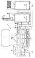
- an installation R is used Generation of energy, in particular energy-compact plant, a housing 1, which preferably sound and is formed heat-insulating.
- the housing is preferred 1 formed air-impermeable.
- a drive unit 2 is provided, which via a dashed line indicated here connection line. 3 with an energy reservoir 4 is in communication.
- the energy reservoir 4 arranged externally to the housing 1. But it should also be there be thought, the energy reservoir 4 in the housing 1 to intergrieren. It provides the necessary energy for that Drive unit 2. This is to gasoline, diesel, rapeseed oil, Bio-oil, from different plants, or other Biostoffen thought.
- the drive unit 2 is connected to a generator 5.
- This generator 5 is connected to a control device 6 in Connection, which via here only indicated lines 7.1, 7.2 makes the distribution and regulation of the stream.
- the Line 7.1 leads to any load, for example, a House. Is only light load, for example, at night, erfrodert, so the controller 6 switches on its own Energy storage 8 um, which are arranged in the housing 1.
- the energy stores 8 are close to one Housing bottom 9 is arranged, and are connected via a partition wall 10 foreclosed.
- the system R delivers, for example, at night without the generator 5 and thus also the drive unit 2 are operated need permanent energy from the energy store 8.
- the Control device 6 assumes the necessary for this Control and regulation. Falls a certain Voltage potential of the energy storage 8 from, so is automatically via the control device 6 the Drive unit 2 turns on and loads the preferably Internally in the housing 1 arranged energy storage 8.
- the generator 5 delivers at higher loads enough power to all loaders eg. one Enough to supply one family house with sufficient energy.
- Another feature of the present invention is that the waste heat of the drive unit 2 is used.
- the heat-insulated housing 1 is inside a generates high heat. This heat gets over Heat exchange devices 11.1, 11.2 used.
- the heat exchange device 11.1 is preferably used as an air and exhaust gas permeable register formed. This is preferably arranged above the drive unit 2, through which the heated air in the housing 1 to the outside can escape.
- the heat exchange device 11.1 is after outside an exhaust air intake element 12 assigned.
- the Exhaust air intake element 12 leads directly into the open and gives the heat or exhaust air of the drive unit 2 over an exhaust duct 13 from. Fresh air is over a the Housing 1 associated inlet 19 supplied. This can too be preheated room air or fresh air.
- the heat exchange device 11.1 is connected by heat pipes 14.1, 14.2 with at least one consumer 15.1, 15.2 in Connection. Appropriate controllable and not closer Numbered valves and heat pumps regulate the volume flow during heat exchange of the heat exchange device 11.1.
- the Customers 15.1, 15.2 can, for example. Boiler for process water or boiler for a heating circuit, as indicated here it's his. In addition, in the boilers electric Heating elements 16.1, 16.2 be provided, which over the Energy storage 8 or directly via the generator. 5 are operable.
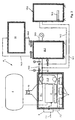
- Another heat exchanger 11.2 is preferably laterally provided in the housing 1. This essentially serves as shown in particular in Figure 2, for Heating of air, the air through a Inlet port 20 flows into the housing 1, through the Heat exchange device 11.2 in DC or Countercurrent method transported on and over a Outlet 17 is supplied to a ventilation system 18.
- the outlet 17 can, for example, directly into a room open out.
- About the ventilation system 18 can individual Rooms, which are connected to it, controllably heated become.
- a further system R 1 is shown, which essentially includes the components shown in Figures 1 and 2. It is different here that connects to the customer 15.1 instead of the heating element 16.1 a heating element 16.3 externally, for example. As a combustion device. About the external heating element 16.3 can be the buyer 15.1 heat up.
- Waste heat preheated water in the customer 15.1, which formed in the present embodiment as a boiler is.
- the heated by waste water in the customer 15.1 can be further heated by the heating element 16.3. This is then over another heat pipes 14.3, 14.4 a Energy converter 21 supplied.
- the Energy converter 21 designed as a steam generator.
- the temperature in the consumer 15.1, especially boiler is so heated that they are used to generate energy, in particular power generation in the energy converter 21, especially steam generator is suitable.
- the waste heat which, for example, won over cogeneration units is heated, the water in the customer 15.1 to about 70 bis 80 ° C.
- About the burner or via the heating element 16.3 must only the temperature difference in the form of energy be supplied to the steam generator or Energy converter 21 is required.
- the temperature in the buyer 15.1 only on Steam generation temperature heated and then the Water vapor to the steam generator to generate energy fed.
- the condensate which comes from the steam generator precipitates, has a temperature of about 90 ° C and can via the heat pipe 14.4 the customer 15.1 directly be supplied. This creates a circulation, wherein only the temperature difference between the Steam production temperature and the temperature in the consumer 15.1 must be supplied by the heating element 16.3.
- the heat exchange device 11.1 a Cogeneration plant assigned.
- This waste heat by means of which in conventional combined heat and power plants a Heating of apartments or other buildings made was, can now be used directly for power generation. This increases the efficiency of combined heat and power plants considerably. The big temperature losses through Pipelines and the like can be omitted.
Landscapes
- Engineering & Computer Science (AREA)
- Chemical & Material Sciences (AREA)
- Combustion & Propulsion (AREA)
- Mechanical Engineering (AREA)
- General Engineering & Computer Science (AREA)
- Physics & Mathematics (AREA)
- Acoustics & Sound (AREA)
- Engine Equipment That Uses Special Cycles (AREA)
- Heat-Pump Type And Storage Water Heaters (AREA)
- Wind Motors (AREA)
Claims (13)
- Installation de production d'énergie compacte avec au moins un ensemble d'entraínement (2) auquel est associé au moins un générateur (5), l'ensemble d'entraínement (2) étant disposé, en vue de l'utilisation de la chaleur résiduelle, dans un boítier (1) isolant acoustique et/ou isolant thermique, ainsi qu'il y est associé au moins un dispositif d'échange de chaleur (11.1, 11.2),
caractérisée par le fait qu'au boítier (1) est présente une entrée (19) comme admission d'air frais, et
que l'un dispositif échangeur de chaleur (11.1) réalisé sous forme de registre perméable à l'air et aux gaz d'échappement est disposé au-dessus de l'ensemble d'entraínement (2) dans le boítier (1) et vient se raccorder à au moins un utilisateur (15.1, 15.2) et que l'autre dispositif échangeur de chaleur (11.2) communique avec un système d'aération (18), ce dispositif échangeur de chaleur (11.2) étant disposé latéralement dans le boítier (1), une tubulure d'entrée (20) et une tubulure de sortie (17) pénétrant dans le boítier (1). - Installation de production d'énergie compacte selon la revendication 1, caractérisée par le fait qu'à l'un dispositif échangeur de chaleur (11.1) vient se raccorder un élément de réception d'air d'échappement (12), éventuellement en forme d'entonnoir, et que l'autre dispositif échangeur de chaleur est réalisé sous forme de registre perméable à l'air.
- Installation de production d'énergie compacte selon la revendication 2, caractérisée par le fait que l'élément de réception d'air d'échappement (12) est disposé à l'extérieur du boítier (1) et présente un canal à air d'échappement (13).
- Installation de production d'énergie compacte selon au moins l'une des revendications 1 à 3, caractérisée par le fait que le dispositif échangeur de chaleur (11.2) peut être raccordé à un système d'aération (18), le dispositif échangeur de chaleur (11.2) pouvant fonctionner dans le boítier (1) selon un procédé à courant direct ou à contre-courant.
- Installation de production d'énergie compacte selon au moins l'une des revendications 1 à 4, caractérisée par le fait que le générateur (5) communique avec une commande électrique (6) pour l'alimentation d'au moins un accumulateur d'énergie intérieur (8) et/ou un utilisateur de charge extérieur.
- Installation de production d'énergie compacte selon la revendication 5, caractérisée par le fait que l'au moins un accumulateur d'énergie (8) est monté à l'intérieur du boítier (1), éventuellement séparé par l'intermédiaire d'une cloison (10).
- Installation de production d'énergie compacte selon la revendication 5 ou 6, caractérisée par le fait que l'accumulateur d'énergie (8) est prévu près d'un fond de boítier (9).
- Installation de production d'énergie compacte selon au moins l'une des revendications 1 à 7, caractérisée par le fait que l'ensemble d'entraínement (2) est relié à un réservoir d'énergie (4) extérieur et/ou intérieur, en particulier un réservoir à combustible.
- Installation de production d'énergie compacte selon au moins l'une des revendications 1 à 8, caractérisée par le fait que la chaleur dégagée de l'ensemble d'entraínement (2) peut être transportée dans les dispositifs échangeurs de chaleur (11.1, 11.2) par l'intermédiaire de fluides les plus divers, tels que de l'air, de l'eau, de l'huile.
- Installation de production d'énergie compacte qui alimente, par l'intermédiaire d'un dispositif échangeur de chaleur (11.1), de la chaleur résiduelle, éventuellement d'une centrale de chauffage à distance, vers au moins un utilisateur (15.1, 15.2), caractérisée par le fait que la température dans l'utilisateur (15.1, 15.2) est élevée au moyen d'au moins un élément chauffant (16.3) et que par l'élévation de la température dans l'utilisateur (15.1, 15.2) peut être entraíné un transformateur d'énergie (21) pour la production d'énergie.
- Installation de production d'énergie compacte selon la revendication 10, caractérisée par le fait qu'à l'au moins un utilisateur (15.1, 15.2) est associé au moins un transformateur d'énergie (21).
- Installation de production d'énergie compacte selon la revendication 10 ou 11, caractérisée par le fait que le transformateur d'énergie (21) est relié, par l'intermédiaire de conduits de chaleur (14.1, 14.2), à l'utilisateur (15.1) et qu'il est éventuellement formé un circuit.
- Installation de production d'énergie compacte selon au moins l'une des revendications 10 à 12, caractérisée par le fait que le transformateur d'énergie (21) est réalisé sous forme de générateur fonctionnant à la vapeur, en vue de générer du courant.
Applications Claiming Priority (4)
| Application Number | Priority Date | Filing Date | Title |
|---|---|---|---|
| DE19809779 | 1998-03-06 | ||
| DE19809779 | 1998-03-06 | ||
| DE19829192 | 1998-06-30 | ||
| DE19829192A DE19829192B4 (de) | 1998-03-06 | 1998-06-30 | Energie-Kompakt-Anlage |
Publications (3)
| Publication Number | Publication Date |
|---|---|
| EP0940637A2 EP0940637A2 (fr) | 1999-09-08 |
| EP0940637A3 EP0940637A3 (fr) | 2001-12-05 |
| EP0940637B1 true EP0940637B1 (fr) | 2005-10-26 |
Family
ID=26044426
Family Applications (1)
| Application Number | Title | Priority Date | Filing Date |
|---|---|---|---|
| EP99103647A Expired - Lifetime EP0940637B1 (fr) | 1998-03-06 | 1999-02-25 | Installation de production d'énergie compacte |
Country Status (3)
| Country | Link |
|---|---|
| EP (1) | EP0940637B1 (fr) |
| DE (2) | DE29812982U1 (fr) |
| ES (1) | ES2247742T3 (fr) |
Families Citing this family (9)
| Publication number | Priority date | Publication date | Assignee | Title |
|---|---|---|---|---|
| EP1057985B1 (fr) * | 1999-05-31 | 2005-10-19 | Nortron ApS | Dispositif compact et méthode pour la production d'énergie |
| DE10003186A1 (de) * | 2000-01-25 | 2001-08-02 | Bhkw Betreiber Gmbh | Verfahren und Vorrichtung zur Strom- und Wärmeerzeugung |
| DE10103522A1 (de) * | 2001-01-26 | 2002-08-29 | Scc Special Comm Cables Gmbh | Kleinspannungs-Versorgungseinrichtung und Gebäude mit einer Kleinspannungs-Versorgungseinrichtung |
| DE10138181A1 (de) * | 2001-08-03 | 2003-02-27 | Elzet Elektrotechnik Gmbh | Verfahren zum Erzeugen von elektrischem Strom |
| GB0208335D0 (en) * | 2002-04-11 | 2002-05-22 | Young Robert L | An automomous unit for supplying energy |
| KR100624816B1 (ko) * | 2004-08-17 | 2006-09-20 | 엘지전자 주식회사 | 열병합 발전 시스템 |
| EP2700802B1 (fr) * | 2012-08-20 | 2017-08-02 | Vaillant GmbH | Centrale de cogénération avec un accumulateur d'électricité intégré |
| DE202013100814U1 (de) * | 2013-01-11 | 2014-04-14 | Becker Marine Systems Gmbh & Co. Kg | Vorrichtung zur Erzeugung von Energie |
| DE202017107002U1 (de) * | 2017-11-18 | 2019-02-19 | Bdr Thermea Group B.V. | Blockheizkraftwerk |
Family Cites Families (4)
| Publication number | Priority date | Publication date | Assignee | Title |
|---|---|---|---|---|
| DE3116624C2 (de) * | 1981-04-27 | 1985-08-29 | Daimler-Benz Ag, 7000 Stuttgart | Energieversorgungssystem für Wärme und Elektrizität |
| US4657290A (en) * | 1984-10-03 | 1987-04-14 | Linden Craig L | Co-generation plant module system |
| US4736111A (en) * | 1984-10-03 | 1988-04-05 | Linden Craig L | Cogeneration system |
| US5719990A (en) * | 1996-03-19 | 1998-02-17 | Yang; Tsai Hui | Hot water and electricity generator |
-
1998
- 1998-07-21 DE DE29812982U patent/DE29812982U1/de not_active Expired - Lifetime
-
1999
- 1999-02-25 ES ES99103647T patent/ES2247742T3/es not_active Expired - Lifetime
- 1999-02-25 EP EP99103647A patent/EP0940637B1/fr not_active Expired - Lifetime
- 1999-02-25 DE DE59912691T patent/DE59912691D1/de not_active Expired - Fee Related
Also Published As
| Publication number | Publication date |
|---|---|
| DE59912691D1 (de) | 2005-12-01 |
| EP0940637A3 (fr) | 2001-12-05 |
| DE29812982U1 (de) | 1998-10-29 |
| EP0940637A2 (fr) | 1999-09-08 |
| ES2247742T3 (es) | 2006-03-01 |
Similar Documents
| Publication | Publication Date | Title |
|---|---|---|
| DE4006742C2 (fr) | ||
| DE19740398C2 (de) | Kraft-Wärme-gekoppelte Einrichtung zur Energieversorgung | |
| DE69027546T2 (de) | Gebäude | |
| EP0940637B1 (fr) | Installation de production d'énergie compacte | |
| DE102008016577A1 (de) | Wärmepumpeneinrichtung | |
| DE19829192B4 (de) | Energie-Kompakt-Anlage | |
| EP2325567A2 (fr) | Système de chauffage | |
| DE10142779A1 (de) | Kompaktheizgerät | |
| DE19527830C2 (de) | Verfahren zum Betrieb einer Heizanlage und Heizanlage | |
| EP2116789A2 (fr) | Centrale de chauffage compacte | |
| DE102009040842A1 (de) | Hocheffizientes, solarunterstütztes Brennwert-Speicherheizgerät für flüssige oder gasförmige Brennstoffe zur Erzeugung von Trinkwarmwasser und Heizwärme zur Raumheizung | |
| DE2848530A1 (de) | Heizungsanlage mit waermepumpe | |
| DE202015006684U1 (de) | Pufferspeicher und Wärmeversorgungssystem enthaltend einen solchen | |
| DE202009013827U1 (de) | Niedrigenergie- oder Passivhaus mit Gasbrenner | |
| DE10149339C1 (de) | Heizungsanlage für ein Gebäude, insbesondere für ein Wohnhaus | |
| DE10043547A1 (de) | Energie-Kompakt-Anlage | |
| DE2512475A1 (de) | Heizungsanlage zur nutzung der sonnenenergie | |
| DE202005009663U1 (de) | Blockheizkraftwerk | |
| DE7715448U1 (de) | Isolierzelle für Wärmepumpen, Wärmespeicher und Warmwasserboiler von Zentralheizungsanlagen | |
| AT255079B (de) | Heizanlage für eine Wohnung oder ein Wohnhaus mit Heißluftbaderaum (Sauna) | |
| DE102018007496B4 (de) | Versorgungsvorrichtung zur Versorgung einer Nutzungseinheit mit Wärme, Kälte, Warmwasser und/oder Luft und Verfahren zum Austausch einer Versorgungsvorrichtung an einem Gebäude oder Raum | |
| DE10148585A1 (de) | Einzelraum-Heizsystem | |
| EP1288581A2 (fr) | Chaudière compacte | |
| DE19914314C2 (de) | Passivhaus und Verfahren zur Restwärmeerzeugung in einem derartigen Passivhaus | |
| DE202023001899U1 (de) | Zusatzheizanordnung zum Erwärmen eines in einer Heizungsanlage umlaufenden Wärmeträgerfluids |
Legal Events
| Date | Code | Title | Description |
|---|---|---|---|
| PUAI | Public reference made under article 153(3) epc to a published international application that has entered the european phase |
Free format text: ORIGINAL CODE: 0009012 |
|
| AK | Designated contracting states |
Kind code of ref document: A2 Designated state(s): AT BE CH CY DE DK ES FI FR GB GR IE IT LI LU MC NL PT SE Kind code of ref document: A2 Designated state(s): BE CH DE ES FR GB GR IT LI LU NL PT |
|
| AX | Request for extension of the european patent |
Free format text: AL;LT;LV;MK;RO;SI |
|
| RIC1 | Information provided on ipc code assigned before grant |
Free format text: 7F 24D 12/02 A, 7F 02G 5/00 B, 7F 02B 63/04 B, 7F 02B 77/13 B |
|
| PUAL | Search report despatched |
Free format text: ORIGINAL CODE: 0009013 |
|
| AK | Designated contracting states |
Kind code of ref document: A3 Designated state(s): AT BE CH CY DE DK ES FI FR GB GR IE IT LI LU MC NL PT SE |
|
| AX | Request for extension of the european patent |
Free format text: AL;LT;LV;MK;RO;SI |
|
| 17P | Request for examination filed |
Effective date: 20020307 |
|
| AKX | Designation fees paid |
Free format text: BE CH DE ES FR GB GR IT LI LU NL PT |
|
| 17Q | First examination report despatched |
Effective date: 20030519 |
|
| RAP1 | Party data changed (applicant data changed or rights of an application transferred) |
Owner name: SCHAKO KLIMA LUFT FERDINAND SCHAD KG |
|
| GRAP | Despatch of communication of intention to grant a patent |
Free format text: ORIGINAL CODE: EPIDOSNIGR1 |
|
| RTI1 | Title (correction) |
Free format text: COMPACT ENERGY INSTALLATION |
|
| RBV | Designated contracting states (corrected) |
Designated state(s): BE CH DE ES FR GB GR IT LI LU PT |
|
| GRAS | Grant fee paid |
Free format text: ORIGINAL CODE: EPIDOSNIGR3 |
|
| RBV | Designated contracting states (corrected) |
Designated state(s): BE CH DE ES FR GB GR IT LI LU NL PT |
|
| GRAA | (expected) grant |
Free format text: ORIGINAL CODE: 0009210 |
|
| AK | Designated contracting states |
Kind code of ref document: B1 Designated state(s): BE CH DE ES FR GB GR IT LI LU NL PT |
|
| PG25 | Lapsed in a contracting state [announced via postgrant information from national office to epo] |
Ref country code: NL Free format text: LAPSE BECAUSE OF FAILURE TO SUBMIT A TRANSLATION OF THE DESCRIPTION OR TO PAY THE FEE WITHIN THE PRESCRIBED TIME-LIMIT Effective date: 20051026 |
|
| REG | Reference to a national code |
Ref country code: GB Ref legal event code: FG4D Free format text: NOT ENGLISH |
|
| REG | Reference to a national code |
Ref country code: CH Ref legal event code: NV Representative=s name: ARIE WUBBEN Ref country code: CH Ref legal event code: EP |
|
| GBT | Gb: translation of ep patent filed (gb section 77(6)(a)/1977) |
Effective date: 20051026 |
|
| REF | Corresponds to: |
Ref document number: 59912691 Country of ref document: DE Date of ref document: 20051201 Kind code of ref document: P |
|
| PG25 | Lapsed in a contracting state [announced via postgrant information from national office to epo] |
Ref country code: GR Free format text: LAPSE BECAUSE OF FAILURE TO SUBMIT A TRANSLATION OF THE DESCRIPTION OR TO PAY THE FEE WITHIN THE PRESCRIBED TIME-LIMIT Effective date: 20060126 |
|
| PG25 | Lapsed in a contracting state [announced via postgrant information from national office to epo] |
Ref country code: GB Free format text: LAPSE BECAUSE OF NON-PAYMENT OF DUE FEES Effective date: 20060225 |
|
| PG25 | Lapsed in a contracting state [announced via postgrant information from national office to epo] |
Ref country code: ES Free format text: LAPSE BECAUSE OF NON-PAYMENT OF DUE FEES Effective date: 20060227 |
|
| PG25 | Lapsed in a contracting state [announced via postgrant information from national office to epo] |
Ref country code: LU Free format text: LAPSE BECAUSE OF NON-PAYMENT OF DUE FEES Effective date: 20060228 Ref country code: LI Free format text: LAPSE BECAUSE OF NON-PAYMENT OF DUE FEES Effective date: 20060228 Ref country code: CH Free format text: LAPSE BECAUSE OF NON-PAYMENT OF DUE FEES Effective date: 20060228 Ref country code: BE Free format text: LAPSE BECAUSE OF NON-PAYMENT OF DUE FEES Effective date: 20060228 |
|
| PGFP | Annual fee paid to national office [announced via postgrant information from national office to epo] |
Ref country code: IT Payment date: 20060228 Year of fee payment: 8 |
|
| REG | Reference to a national code |
Ref country code: ES Ref legal event code: FG2A Ref document number: 2247742 Country of ref document: ES Kind code of ref document: T3 |
|
| PG25 | Lapsed in a contracting state [announced via postgrant information from national office to epo] |
Ref country code: PT Free format text: LAPSE BECAUSE OF FAILURE TO SUBMIT A TRANSLATION OF THE DESCRIPTION OR TO PAY THE FEE WITHIN THE PRESCRIBED TIME-LIMIT Effective date: 20060327 |
|
| NLV1 | Nl: lapsed or annulled due to failure to fulfill the requirements of art. 29p and 29m of the patents act | ||
| ET | Fr: translation filed | ||
| PG25 | Lapsed in a contracting state [announced via postgrant information from national office to epo] |
Ref country code: DE Free format text: LAPSE BECAUSE OF NON-PAYMENT OF DUE FEES Effective date: 20060901 |
|
| PLBE | No opposition filed within time limit |
Free format text: ORIGINAL CODE: 0009261 |
|
| STAA | Information on the status of an ep patent application or granted ep patent |
Free format text: STATUS: NO OPPOSITION FILED WITHIN TIME LIMIT |
|
| 26N | No opposition filed |
Effective date: 20060727 |
|
| REG | Reference to a national code |
Ref country code: CH Ref legal event code: PL |
|
| GBPC | Gb: european patent ceased through non-payment of renewal fee |
Effective date: 20060225 |
|
| REG | Reference to a national code |
Ref country code: ES Ref legal event code: FD2A Effective date: 20060227 |
|
| BERE | Be: lapsed |
Owner name: SCHAKO KLIMA LUFT FERDINAND *SCHAD K.G. Effective date: 20060228 |
|
| PG25 | Lapsed in a contracting state [announced via postgrant information from national office to epo] |
Ref country code: FR Free format text: LAPSE BECAUSE OF NON-PAYMENT OF DUE FEES Effective date: 20060228 |
|
| PG25 | Lapsed in a contracting state [announced via postgrant information from national office to epo] |
Ref country code: IT Free format text: LAPSE BECAUSE OF NON-PAYMENT OF DUE FEES Effective date: 20070225 |
|
| REG | Reference to a national code |
Ref country code: FR Ref legal event code: ST Effective date: 20110218 |