EP0940642A2 - Distributeur de glace et / ou de boissons - Google Patents
Distributeur de glace et / ou de boissons Download PDFInfo
- Publication number
- EP0940642A2 EP0940642A2 EP99301322A EP99301322A EP0940642A2 EP 0940642 A2 EP0940642 A2 EP 0940642A2 EP 99301322 A EP99301322 A EP 99301322A EP 99301322 A EP99301322 A EP 99301322A EP 0940642 A2 EP0940642 A2 EP 0940642A2
- Authority
- EP
- European Patent Office
- Prior art keywords
- ice
- door
- stopper
- solenoid
- dispenser
- Prior art date
- Legal status (The legal status is an assumption and is not a legal conclusion. Google has not performed a legal analysis and makes no representation as to the accuracy of the status listed.)
- Granted
Links
Images


Classifications
-
- F—MECHANICAL ENGINEERING; LIGHTING; HEATING; WEAPONS; BLASTING
- F25—REFRIGERATION OR COOLING; COMBINED HEATING AND REFRIGERATION SYSTEMS; HEAT PUMP SYSTEMS; MANUFACTURE OR STORAGE OF ICE; LIQUEFACTION SOLIDIFICATION OF GASES
- F25C—PRODUCING, WORKING OR HANDLING ICE
- F25C5/00—Working or handling ice
- F25C5/20—Distributing ice
- F25C5/22—Distributing ice particularly adapted for household refrigerators
Definitions
- the present invention relates to an ice and/or beverage dispenser including a supply duct having a door, a switch actuable when the door is in an open position to cause the dispenser to dispense beverage and/or ice through the supply duct, biasing means for urging the door towards a closed position when the switch is deactivated, and control means for controlling movement of the door from the open to the closed position.
- a refrigerator is a container that is usually powered by electricity and has a storage space for foodstuffs which is maintained at a low temperature to keep them fresh for an extended period of time.
- a conventional ice dispenser of the type incorporated in a refrigerator is illustrated in Figure 1 and includes an ice reservoir 20 having an ice supplier 21 mounted inside the refrigerator.
- the refrigerator door 10 has a cavity 30 for receiving a cup C and the ice reservoir 20 communicates with the cavity 30 through a supply duct 40 so that pieces of ice can be supplied to the cup C from the ice reservoir 20 through the supply duct 40.
- a bracket 32 is mounted to the refrigerator door 10 on the upper surface of the cavity 30 and a door 31 operable to open and close the supply duct 40 is pivotally connected to the bracket 32.
- a biasing member 33 urges the door 31 into a closed position when the dispenser is not in operation.
- the dispenser further comprises a lever having a first end 34 disposed on one side of the door 31 and a second end 35 extending into the cavity 30.
- the lever is pivotally mounted to the cavity wall midway between its and first and second ends 34,35. The arrangement is such that when cup C is inserted into the cavity 30, the second end 35 of the lever comes into contact with the cup. Further movement of the cup into the cavity causes the lever to pivot which moves the first end 34 outward, overcoming the biasing force caused by the biasing member 33 and opening the supply duct 40 (see Figure 1 in phantom).
- the lever As the second end 35 of the lever moves inwardly, it activates a switch 36 to operate the ice supplier 21 mounted inside the door 10 to cause pieces of ice to be dispensed from the ice reservoir 20 to the cup C through the supply duct 40.
- the damper 37 comprises a damper housing 38a formed from a portion of the inner wall of the cavity 30, a piston 38b slidably disposed in the damper housing 38a, and a rod 38c coupled at one end to the first lever 34 and at its other end to the piston 38b.
- the rod 38c is withdrawn from the damper 37 when the damper door 31 is opened and returns into the damper housing 38a by biasing force of the elastic member 33 when the door 31 is closed.
- a disadvantage with a conventional ice dispenser such as the type described above is that the damping force of the damper 37 changes during continued use, reducing the time taken for the door 31 to return to the closed position, thereby causing the supply duct 40 to close too quickly. As a result, ice is caught between the supply duct 40 and the door 31 or remains within the supply duct 40, reducing the reliability of the dispenser.
- a dispenser of this type is illustrated in Figures 2A and 2B and comprises a door 51 to open and close a supply duct 60 and an actuator 80 to pivot the door 51 between its open and closed positions.
- the actuator 80 includes a spring biased piston 81.
- An arm 52 is mounted between the door 51 and the actuator 80 and pivots about a pivot shaft 53 together with the door 51.
- the actuator 80 is electrically energised causing fluid within the actuator 80 to vaporise and extend the piston 81 against the internal spring to the position shown in phantom in the drawings.
- the actuator 80 When the cup C is withdrawn from the cavity 70, the actuator 80 is de-energised, the vapour cools and, after a delay, the internal spring moves the piston 81 back to its retracted position causing the door 51 to return to its closed position. As there is a delay after the dispenser is de-actuated, sufficient time is allowed to permit all the ice remaining in the supply duct 60 to exit the supply duct 60 before the door 51 is closed.
- a disadvantage with the second type of conventional dispenser described above is that it is necessary to continually supply electric power to the actuator 80 to maintain the door 51 in an open position when the dispenser is in use. Furthermore, a considerable operating force is required to completely open and close the door 51 which increases power consumption and reduces efficiency. This is largely because a spring having a high elastic coefficient is required to maintain the door 51 in tight contact with the outlet of the supply duct 60 when the door is closed, thus the actuator 80 has to be of a sufficient size to operate the piston 81 against the force of the spring.
- An ice dispenser according to the present invention is characterised in that the control means is operable to maintain the door in the open position for a predetermined time period after deactivation of the switch.
- control means includes a solenoid and a catch, the solenoid being operable to release the catch after the predetermined time period has elapsed.
- the catch comprises a catch member associated with the door slidable through an opening in a support member, the catch member having a shoulder engageable with the support member to prevent movement of the door from the open to the closed position.
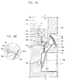
- an ice dispenser comprising an ice reservoir 110 in which an ice supplier 111 is located mounted within a refrigerator.
- the refrigerator door 100 has a cavity 120 to enable ice to be dispensed into a cup C located within the cavity 120 when the refrigerator door 100 is closed.
- the ice reservoir 110 communicates with the cavity 120 through an ice supply duct 140.
- a bracket 122 is fixedly mounted to the top surface of the cavity 120 and a door 121 for opening and closing the ice supply duct 140 is pivotally mounted to the bracket 122.
- a biasing member 123 is also mounted to the bracket 122 to urge the door 121 into a closed position when the dispenser is not in use.
- a dispenser operating lever assembly 124 is pivotally mounted to an inner wall of the cavity 120 and comprises a mounting lever 125a pivotally fixed to the inner wall of the cavity 120, a door opening portion 125b extending upwardly to one side of the door 121, and a switch operating portion 125c extending downwardly into the cavity 120.
- a switch 126 for operating the ice supplier 111 is mounted on the inner wall of the cavity 120 which is activated when the switch operating portion 125c of the lever assembly 124 is deflected inwardly as a cup C is placed in the cavity 120.
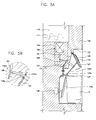
- the lever assembly 124 pivots such that the switch operating portion 125c moves toward the inner wall of the cavity 120 and the switch 126 is pushed by the switch operating portion 125c.
- the dispenser operating lever assembly 124 is pivoted. That is, the switch operating portion 125c is pushed by the cup C toward the inner wall of the cavity 120, and the door opening portion 125b moves simultaneously to pivot the damper door 121 to an open position while overcoming the biasing force of the biasing member 123, thereby opening the ice supply duct 140.
- the switch 126 is activated by the switch operating portion 125c displaced toward the inner wall of the cavity 120, the ice supplier 111 is operated to dispense ice from the ice reservoir 110 into the cup C through the ice supply duct 140.
- the cup C When a sufficient amount of ice has been dispensed, the cup C is removed from the cavity 120 as shown in Figure 5A, which releases the pushing force applied to the switch operating portion 125c and the door is returned to its closed position due to the biasing force of the biasing member 123.
- the switch 126 is also deactivated to prevent any further supply of ice from the ice supplier 111.
- the dispenser according to the first preferred embodiment is provided with retardation means for holding the door in an open state for a predetermined period of time after deactivation of the switch when the cup is removed, and retardation release means for releasing the retardation means to allow the door 121 to return to its closed position and close ice supply duct 140.
- the retardation means comprises an arcuate member 128 pivotally coupled at one end to the door opening portion 125b and provided with a shoulder 128a on its lower side.
- a supporting bracket 127 provided with a slot 127a through which the arcuate member 128 passes is mounted to the inner wall of the cavity 120 to restrict the movement of the arcuate member 128.
- retardation release means is provided and comprises a solenoid 130, for elevating/lowering the arcuate member 128, disposed above the arcuate member 128.
- the solenoid 130 is controlled by a microcomputer (not shown) and connected to the arcuate member 128 via a plunger 131.
- the plunger 131 is provided with a through hole 131a through which the arcuate member 128 passes.
- the door 121 is maintained in its closed position by the biasing force provided by the biasing member 123 to maintain the ice supply duct 140 closed.
- the switch operating portion 125c activates the switch 126 to operate the ice supplier 111 within the ice reservoir 110 and simultaneously cause the damper door operating portion 125b to pivot to overcome the biasing force of the biasing member 123 and move the door 121 into an open position.
- the ice supply duct 140 is then open and ice is dispensed from the ice reservoir 110 to the cup C through the ice supply duct 140.
- the dispenser operating lever assembly 124 pivots and the damper door 121 begins to move toward its closed position by the biasing force provided by the elastic member 123 and, simultaneously, the switch operating portion 125c moves away from the inner wall of the cavity 120 and deactivates the switch 126 to stop operation of the ice supplier 111. Movement of the arcuate member 128 is stopped as the shoulder 128a formed on the lower side of the arcuate member 128 is caught against the supporting bracket 127 and the return of the damper door 121 is prevented, thereby maintaining the ice supply tube 140 open for a predetermined time.
- the microcomputer sends a signal to the solenoid 130 so that the plunger 131 moves upward to elevate the arcuate member 128 and release the arcuate member from the supporting bracket 127.
- the arcuate member 128 then freely passes through the slot 127a of the supporting bracket 127, and causes the door 121to return to its closed position.
- the solenoid 130 is de-energised by the microcomputer and the plunger 131 moves downward to its initial position.
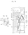
- the retardation means comprises arcuate member 228 pivotally coupled at its one end to the damper door opening lever 125b and provided with a shoulder 228a on its upper side.
- a support bracket 227 is mounted on the inner wall of the cavity 120 to restrict movement of the arcuate member 228.
- the support bracket 227 is provided with a slot 227a through which the arcuate member 228 passes.
- the retardation release means disposed above the arcuate member 228 comprises a solenoid 230 to elevate/lower the arcuate member 228.
- the solenoid 230 is controlled by a microcomputer (not shown) and connected to the stopper 228 via a plunger 231.
- the plunger 231 is provided with a through hole 231a through which the arcuate member 228 passes.
- a roller 232 is disposed in the through hole 231a to allow the arcuate member 228 to move smoothly through the hole 231a. Referring to Figure 7A, as the cup C is located in the cavity 120, the door opening portion 125b moves to open the door 121, and the arcuate member 228 coupled to the door opening portion 125b also moves in a direction where the door 121 is opened.
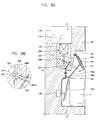
- the microcomputer sends a signal to the solenoid 230 such that the plunger 231 moves upward to elevate the stopper 228.
- the cup C is withdrawn out of the cavity 120, the door 121, the door opening portion 125b, and the arcuate member 228 start returning to their initial positions by the biasing force provided by the biasing member 123. Movement of the arcuate member 228 is prevented as the shoulder 228a formed on the upper side of the stopper 228 engages with the supporting bracket 227, to maintain the ice supply duct 140 open for a predetermined length of time.
- the solenoid 230 is de-energised by the microcomputer such that the plunger 231 moves downward, thereby lowering the arcuate member 228 inserted in the through hole 231a of the plunger 231 and releasing it from the support bracket 227 as shown in Figure 8B to enable the arcuate member 228 to completely pass through the slot 227a of the support bracket 227 and return the door 121 to its closed position.
- the damper door 121 is maintained in its closed position by the biasing force provided by biasing member 123 to close the ice supply duct 140.
- the switch operating portion 125c activates the switch 126 to operate the ice supplier 111 within the ice reservoir 110 and simultaneously pivots the door operating portion 125b against the spring bias to open the door 121.
- the ice supply duct 140 is then open to dispense ice from the ice reservoir 110 into the cup C through the ice supply duct 140.
- the arcuate member 228 coupled to the door operating portion 125b moves in a direction where the door 121 is opened and, at the same time, the microcomputer applies electric power to the solenoid 230 such that the plunger 231 moves upward to elevate stopper 228.
- the solenoid 230 is de-energised by the microcomputer such that the plunger 231 moves downward to lower the arcuate member 228 and release the shoulder 228a from the supporting bracket 227 to enable the arcuate member 228 to completely pass through the slot 227a of the support bracket 227 and return the door 121 to its closed position to close the ice supply duct 140.
- the ice dispenser of a refrigerator is provided with an arcuate member having a shoulder for retarding the return of a door over the ice supply duct, and a solenoid for releasing the door after a predetermined time has elapsed.
- an electric signal is only temporarily supplied to the solenoid and so electric power consumption is reduced.
- electric power is continually applied to the solenoid when the damper door is open as described in the second preferred embodiment, only a relatively small operating force is required to elevate or lower the arcuate member to the height of the shoulder, thereby minimising the power required by the solenoid and improving the reliability of the dispenser.
Landscapes
- Engineering & Computer Science (AREA)
- Physics & Mathematics (AREA)
- Mechanical Engineering (AREA)
- Thermal Sciences (AREA)
- General Engineering & Computer Science (AREA)
- Confectionery (AREA)
- Production, Working, Storing, Or Distribution Of Ice (AREA)
- Beverage Vending Machines With Cups, And Gas Or Electricity Vending Machines (AREA)
- Devices For Dispensing Beverages (AREA)
- Devices That Are Associated With Refrigeration Equipment (AREA)
Applications Claiming Priority (6)
| Application Number | Priority Date | Filing Date | Title |
|---|---|---|---|
| KR9806860 | 1998-03-03 | ||
| KR19980006860 | 1998-03-03 | ||
| KR19980014260 | 1998-07-30 | ||
| KR9814260 | 1998-07-30 | ||
| KR9903176 | 1999-02-01 | ||
| KR1019990003176A KR100283780B1 (ko) | 1998-03-03 | 1999-02-01 | 냉장고의 얼음 디스펜서 |
Publications (3)
| Publication Number | Publication Date |
|---|---|
| EP0940642A2 true EP0940642A2 (fr) | 1999-09-08 |
| EP0940642A3 EP0940642A3 (fr) | 2000-01-12 |
| EP0940642B1 EP0940642B1 (fr) | 2003-05-07 |
Family
ID=27349693
Family Applications (1)
| Application Number | Title | Priority Date | Filing Date |
|---|---|---|---|
| EP99301322A Expired - Lifetime EP0940642B1 (fr) | 1998-03-03 | 1999-02-23 | Distributeur de glace et / ou de boissons |
Country Status (5)
| Country | Link |
|---|---|
| US (1) | US6135173A (fr) |
| EP (1) | EP0940642B1 (fr) |
| JP (1) | JP3112450B2 (fr) |
| CN (1) | CN1105901C (fr) |
| DE (1) | DE69907547T2 (fr) |
Cited By (7)
| Publication number | Priority date | Publication date | Assignee | Title |
|---|---|---|---|---|
| EP1517104A1 (fr) * | 2003-09-18 | 2005-03-23 | Lg Electronics Inc. | Système de distribution de glace pour réfrigérateur |
| EP1482263A3 (fr) * | 2003-05-28 | 2006-05-03 | Lg Electronics Inc. | Réfrigérateur avec un générateur de glace |
| WO2007000028A1 (fr) * | 2005-06-28 | 2007-01-04 | Fluid Fashions Pty Ltd | Systeme distributeur de boisson |
| EP1903287A2 (fr) | 2006-09-21 | 2008-03-26 | LG Electronics Inc. | Réfrigérateur |
| EP2084470A4 (fr) * | 2006-11-13 | 2015-02-25 | Lg Electronics Inc | Distributeur de réfrigérateur le comprenant |
| US9004325B2 (en) | 2012-11-06 | 2015-04-14 | Whirlpool Corporation | Domestic refrigerator including an ice dispenser |
| EP1898166A3 (fr) * | 2006-09-05 | 2016-02-17 | LG Electronics Inc. | Réfrigérateur |
Families Citing this family (71)
| Publication number | Priority date | Publication date | Assignee | Title |
|---|---|---|---|---|
| US6165516A (en) | 1996-11-27 | 2000-12-26 | Wm. Wrigley Jr. Company | Method of controlling release of caffeine in chewing gum |
| KR200170259Y1 (ko) * | 1999-09-03 | 2000-02-15 | 삼성전자주식회사 | 냉장고의 얼음토출구 개폐장치 |
| US20060283332A1 (en) | 2001-12-11 | 2006-12-21 | Garman Michael H | Hot beverage maker |
| US20060196365A1 (en) * | 2001-12-11 | 2006-09-07 | Garman Michael H | Combined water cooler and hot beverage maker |
| US7461586B2 (en) * | 2001-12-11 | 2008-12-09 | Hamilton Beach Brands, Inc. | Hot beverage maker with cup-actuated, low-drip dispenser |
| US6564975B1 (en) | 2001-12-11 | 2003-05-20 | Hamilton Beach/Proctor Silex, Inc. | Hot beverage maker with cup-actuated dispenser |
| US6658887B2 (en) * | 2002-04-17 | 2003-12-09 | Lg Electronics Inc. | Dispenser and refrigerator fitted with the same |
| US6964351B2 (en) * | 2003-04-17 | 2005-11-15 | Imi Cornelius, Inc. | Ice dispensing chute |
| KR100577184B1 (ko) * | 2003-05-28 | 2006-05-10 | 엘지전자 주식회사 | 냉장고 |
| KR100510698B1 (ko) * | 2003-09-17 | 2005-08-31 | 엘지전자 주식회사 | 냉장고의 제빙장치용 디스펜서 |
| JP4518802B2 (ja) * | 2004-01-09 | 2010-08-04 | ホシザキ電機株式会社 | 氷ディスペンサ |
| CN100432594C (zh) * | 2004-04-12 | 2008-11-12 | 乐金电子(天津)电器有限公司 | 冰箱门结构 |
| US7455085B2 (en) * | 2004-06-04 | 2008-11-25 | Whirlpool Corporation | Water dispenser for refrigerator freezers |
| CA2521359A1 (fr) * | 2004-09-27 | 2006-03-27 | Maytag Corporation | Dispositif et methode de distribution de glace a partir d'un refrigerateur de fond |
| KR20060029099A (ko) * | 2004-09-30 | 2006-04-04 | 삼성전자주식회사 | 냉장고 제어방법 |
| KR100707347B1 (ko) * | 2004-09-30 | 2007-04-13 | 삼성전자주식회사 | 냉장고 |
| US7266951B2 (en) * | 2004-10-26 | 2007-09-11 | Whirlpool Corporation | Ice making and dispensing system |
| US6971304B1 (en) * | 2004-11-24 | 2005-12-06 | Uni-Splendor Corp. | Coffee making device |
| US7340914B2 (en) * | 2005-01-03 | 2008-03-11 | Whirlpool Corporation | Refrigerator with a water and ice dispenser having a retractable ledge |
| US7250588B2 (en) | 2005-02-17 | 2007-07-31 | Back To Basics Products, Llc | Combination bread toaster and steamer device |
| KR20060115073A (ko) * | 2005-05-04 | 2006-11-08 | 삼성전자주식회사 | 얼음공급장치 및 이를 갖춘 냉장고 |
| US7568357B2 (en) * | 2005-05-18 | 2009-08-04 | Maytag Corporation | Freeze tolerant waterline valve for a refrigerator |
| US7726148B2 (en) * | 2005-05-18 | 2010-06-01 | Maytag Corporation | Refrigerator ice compartment seal |
| US7900465B2 (en) * | 2005-05-27 | 2011-03-08 | Maytag Corporation | Insulated ice compartment for bottom mount refrigerator with controlled damper |
| US7284390B2 (en) * | 2005-05-18 | 2007-10-23 | Whirlpool Corporation | Refrigerator with intermediate temperature icemaking compartment |
| US7337620B2 (en) * | 2005-05-18 | 2008-03-04 | Whirlpool Corporation | Insulated ice compartment for bottom mount refrigerator |
| US7252035B2 (en) * | 2005-06-20 | 2007-08-07 | Uni-Splender Corp | Coffee maker |
| US20060283330A1 (en) * | 2005-06-20 | 2006-12-21 | Uni-Splendor Corp. | Coffee maker with height adjustment mechanism |
| DE102005057164A1 (de) * | 2005-11-30 | 2007-05-31 | BSH Bosch und Siemens Hausgeräte GmbH | Ausgabevorrichtung für fließ- oder schüttfähige Güter |
| US7383690B2 (en) * | 2005-12-05 | 2008-06-10 | Whirlpool Corporation | Ice harvest prevention mechanism in a refrigerator |
| US7712328B2 (en) * | 2006-03-02 | 2010-05-11 | Harris Teresa L | Refrigerator and appliance system with ice and water dispensing assemblies accessible from multiple sides |
| KR100766119B1 (ko) * | 2006-04-14 | 2007-10-11 | 엘지전자 주식회사 | 냉장고용 디스펜서의 스위칭장치 |
| USD564280S1 (en) | 2006-06-01 | 2008-03-18 | Back To Basics Products, Llc | Coffee maker |
| KR100835183B1 (ko) * | 2006-08-30 | 2008-06-04 | 엘지전자 주식회사 | 냉장고 |
| KR100776294B1 (ko) * | 2006-08-30 | 2007-11-16 | 엘지전자 주식회사 | 냉장고 |
| KR101275564B1 (ko) * | 2006-09-08 | 2013-06-14 | 엘지전자 주식회사 | 냉장고 |
| EP2092256B1 (fr) * | 2006-12-11 | 2017-04-19 | LG Electronics, Inc. | Réfrigérateur équipé d'un distributeur |
| US8220283B2 (en) * | 2006-12-21 | 2012-07-17 | Whirlpool Corporation | Ice crushing mechanism |
| US7814762B2 (en) * | 2007-01-17 | 2010-10-19 | Sub-Zero, Inc. | Integrated ice dispenser switch |
| KR100869510B1 (ko) * | 2007-01-18 | 2008-11-19 | 엘지전자 주식회사 | 냉장고 및 그 제어방법 |
| KR100797480B1 (ko) * | 2007-01-18 | 2008-01-24 | 엘지전자 주식회사 | 냉장고 |
| WO2008096982A1 (fr) | 2007-02-05 | 2008-08-14 | Lg Electronics Inc. | Réfrigérateur avec distributeur |
| KR101349982B1 (ko) * | 2007-02-05 | 2014-01-13 | 엘지전자 주식회사 | 냉장고 및 냉장고 디스펜서 |
| US7581571B2 (en) * | 2007-03-14 | 2009-09-01 | Fluid Managment Operations, Llc | Manually operable manifold/nozzle closure for fluid dispenser |
| US8701436B2 (en) * | 2007-06-20 | 2014-04-22 | Lg Electronics Inc. | Pivotable water dispenser for a refrigerator door |
| DE102007038182B4 (de) | 2007-08-13 | 2011-01-20 | Emz-Hanauer Gmbh & Co. Kgaa | Eisspender für einen Kühlschrank |
| KR101413470B1 (ko) * | 2007-10-08 | 2014-07-01 | 엘지전자 주식회사 | 냉장고의 디스펜서 |
| KR101474013B1 (ko) * | 2008-01-21 | 2014-12-17 | 엘지전자 주식회사 | 냉장고의 물공급 장치 |
| DE102008013750A1 (de) * | 2008-03-12 | 2009-09-24 | Emz-Hanauer Gmbh & Co. Kgaa | Eisklappenvorrichtung für einen Kühlschrank |
| KR101545022B1 (ko) * | 2008-11-14 | 2015-08-17 | 엘지전자 주식회사 | 제빙장치 및 그 제어방법 |
| KR101504214B1 (ko) * | 2008-11-28 | 2015-03-19 | 엘지전자 주식회사 | 디스펜서를 구비한 냉장고 |
| KR101525841B1 (ko) * | 2008-12-11 | 2015-06-08 | 엘지전자 주식회사 | 디스펜서를 구비한 냉장고 |
| JP2010203741A (ja) | 2009-03-05 | 2010-09-16 | Panasonic Corp | 冷蔵庫 |
| JP2010203742A (ja) | 2009-03-05 | 2010-09-16 | Panasonic Corp | 冷蔵庫 |
| DE102009044032B4 (de) * | 2009-09-17 | 2012-10-18 | Miele & Cie. Kg | Haushaltsgerät mit einer Ausgabeeinrichtung für Getränke und/oder Eis |
| US8807022B2 (en) * | 2009-10-12 | 2014-08-19 | Alan Backus | Devices and methods to disintegrate foods |
| US8857206B2 (en) * | 2009-12-07 | 2014-10-14 | Whirlpool Corporation | Multifunction dispenser actuation pad |
| US8640483B2 (en) * | 2009-12-14 | 2014-02-04 | Whirlpool Corporation | Ice guide funnel |
| KR101776297B1 (ko) * | 2010-01-29 | 2017-09-07 | 엘지전자 주식회사 | 냉장고 |
| KR101239327B1 (ko) * | 2011-03-30 | 2013-03-05 | 정휘동 | 얼음 저장고 도어, 및 이를 구비하는 얼음 정수기와 얼음 냉온수기 |
| KR20140112502A (ko) | 2011-12-09 | 2014-09-23 | 일렉트로룩스 홈 프로덕츠 인코퍼레이티드 | 싱글 패들 얼음 및 물 디스펜서 |
| EP2804511B1 (fr) * | 2012-01-17 | 2018-03-21 | Koninklijke Philips N.V. | Buse de distribution ajustable |
| WO2015002874A2 (fr) | 2013-07-03 | 2015-01-08 | The Coca-Cola Company | Distributeur de glaçons |
| US9228777B2 (en) * | 2013-07-16 | 2016-01-05 | BSH Hausgeräte GmbH | Cooling device comprising a dispenser |
| CN104773396B (zh) * | 2015-01-30 | 2017-03-29 | 青岛海尔股份有限公司 | 颗粒物容器及具有该颗粒物容器的冰箱 |
| KR102432001B1 (ko) | 2015-10-14 | 2022-08-16 | 삼성전자주식회사 | 냉장고 |
| CN108236377A (zh) * | 2015-11-11 | 2018-07-03 | 颜秀分 | 一种加冰装置的组装方法 |
| US9738504B2 (en) | 2015-12-17 | 2017-08-22 | Whirlpool Corporation | Low force actuation dispenser paddle for a dispenser assembly of an appliance |
| WO2020075818A1 (fr) * | 2018-10-10 | 2020-04-16 | 株式会社Lsiメディエンス | Unité de mise au rebut de cuvette |
| US11209201B2 (en) * | 2018-11-28 | 2021-12-28 | Bsh Hausgeraete Gmbh | Ice maker with specifically positioned drive unit, household refrigeration apparatus and method for assembling an ice maker |
| KR20220030630A (ko) * | 2020-09-03 | 2022-03-11 | 엘지전자 주식회사 | 냉장고 |
Citations (1)
| Publication number | Priority date | Publication date | Assignee | Title |
|---|---|---|---|---|
| US5526854A (en) | 1992-11-02 | 1996-06-18 | White Consolidated Industries, Inc. | Through the door water and ice dispenser |
Family Cites Families (14)
| Publication number | Priority date | Publication date | Assignee | Title |
|---|---|---|---|---|
| US3537132A (en) * | 1968-09-03 | 1970-11-03 | Gen Electric | Household refrigerator with through-the-door ice service |
| US3789620A (en) * | 1972-11-27 | 1974-02-05 | Gen Motors Corp | Ice door mechanism |
| US3942334A (en) * | 1975-01-08 | 1976-03-09 | Amana Refrigeration, Inc. | Door delay closing mechanism for the ice chute from a power driven ice dispenser in a freezer-refrigerator |
| US4069545A (en) * | 1975-12-24 | 1978-01-24 | General Electric Company | Door control device with closure regulator |
| JPS52132460A (en) * | 1976-04-28 | 1977-11-07 | Hajime Honda | Liquid controller |
| US4090641A (en) * | 1976-08-26 | 1978-05-23 | Whirlpool Corporation | Refrigerator ice door mechanism |
| JPS5539414A (en) * | 1978-09-13 | 1980-03-19 | Fujitsu Ltd | Frame synchronous protecting system |
| US4220266A (en) * | 1978-09-28 | 1980-09-02 | White Consolidated Industries, Inc. | Ice door delay mechanism |
| GB2060979B (en) * | 1979-10-12 | 1983-10-26 | Digital Equipment Corp | Magnetic disc data storage apparatus |
| JPS5660067A (en) * | 1979-10-22 | 1981-05-23 | Toshiba Corp | Semiconductor radiation detector |
| US4462437A (en) * | 1981-12-09 | 1984-07-31 | General Electric Company | Door control device with closure regulator |
| US5129547A (en) * | 1988-07-14 | 1992-07-14 | Charles Fisher | Cable operated ice dispensing door |
| US5267672A (en) * | 1992-08-04 | 1993-12-07 | Leer Manufacturing Limited Partnership | Ice dispenser and display |
| US5860564A (en) * | 1995-09-07 | 1999-01-19 | Imi Cornelius Inc. | Ice dispensing chute |
-
1999
- 1999-02-22 JP JP11043385A patent/JP3112450B2/ja not_active Expired - Fee Related
- 1999-02-23 DE DE69907547T patent/DE69907547T2/de not_active Expired - Lifetime
- 1999-02-23 EP EP99301322A patent/EP0940642B1/fr not_active Expired - Lifetime
- 1999-03-01 US US09/259,677 patent/US6135173A/en not_active Expired - Lifetime
- 1999-03-02 CN CN99102556A patent/CN1105901C/zh not_active Expired - Fee Related
Patent Citations (1)
| Publication number | Priority date | Publication date | Assignee | Title |
|---|---|---|---|---|
| US5526854A (en) | 1992-11-02 | 1996-06-18 | White Consolidated Industries, Inc. | Through the door water and ice dispenser |
Cited By (12)
| Publication number | Priority date | Publication date | Assignee | Title |
|---|---|---|---|---|
| EP1482263A3 (fr) * | 2003-05-28 | 2006-05-03 | Lg Electronics Inc. | Réfrigérateur avec un générateur de glace |
| EP1517104A1 (fr) * | 2003-09-18 | 2005-03-23 | Lg Electronics Inc. | Système de distribution de glace pour réfrigérateur |
| US7040111B2 (en) | 2003-09-18 | 2006-05-09 | Lg Electronics Inc. | Ice supplying device of refrigerator |
| WO2007000028A1 (fr) * | 2005-06-28 | 2007-01-04 | Fluid Fashions Pty Ltd | Systeme distributeur de boisson |
| EP1898166A3 (fr) * | 2006-09-05 | 2016-02-17 | LG Electronics Inc. | Réfrigérateur |
| EP1903287A2 (fr) | 2006-09-21 | 2008-03-26 | LG Electronics Inc. | Réfrigérateur |
| CN100541064C (zh) * | 2006-09-21 | 2009-09-16 | Lg电子株式会社 | 冰箱 |
| EP1903287A3 (fr) * | 2006-09-21 | 2012-06-13 | LG Electronics Inc. | Réfrigérateur |
| EP2084470A4 (fr) * | 2006-11-13 | 2015-02-25 | Lg Electronics Inc | Distributeur de réfrigérateur le comprenant |
| US9004325B2 (en) | 2012-11-06 | 2015-04-14 | Whirlpool Corporation | Domestic refrigerator including an ice dispenser |
| US9518772B2 (en) | 2012-11-06 | 2016-12-13 | Whirlpool Corporation | Domestic refrigerator including an ice dispenser |
| US9927163B2 (en) | 2012-11-06 | 2018-03-27 | Whirlpool Corporation | Domestic refrigerator including an ice dispenser |
Also Published As
| Publication number | Publication date |
|---|---|
| JPH11287550A (ja) | 1999-10-19 |
| US6135173A (en) | 2000-10-24 |
| DE69907547D1 (de) | 2003-06-12 |
| JP3112450B2 (ja) | 2000-11-27 |
| CN1105901C (zh) | 2003-04-16 |
| EP0940642A3 (fr) | 2000-01-12 |
| DE69907547T2 (de) | 2004-01-15 |
| EP0940642B1 (fr) | 2003-05-07 |
| CN1227908A (zh) | 1999-09-08 |
Similar Documents
| Publication | Publication Date | Title |
|---|---|---|
| EP0940642B1 (fr) | Distributeur de glace et / ou de boissons | |
| US3934757A (en) | Refrigerator water dispenser with child-proof guard | |
| US8113248B2 (en) | Dispenser related technology | |
| US6832701B2 (en) | Self metering dispensing device | |
| JPH06201240A (ja) | ドア貫通型氷ディスペンサ並びに氷および水ディスペンサ | |
| CA2765079A1 (fr) | Systeme et procede d'acceptation de depot pour distributeur automatique de billets de banque | |
| US20090133430A1 (en) | Dispensing system and method for dispensing fluid in an appliance | |
| US6012604A (en) | Article ejecting device of automatic vending machine | |
| US5947006A (en) | Toaster with multiple positions for the bread carrier | |
| EP1903287B1 (fr) | Réfrigérateur | |
| US11332917B2 (en) | Flush water tank apparatus and flush toilet apparatus provided with the same | |
| US7712322B2 (en) | Ice level sensing device for an automatic ice maker in a refrigerator | |
| US6405906B1 (en) | Device and method for dispensing a product on a product sampler | |
| US8336325B2 (en) | Ice dispenser for a refrigerator | |
| KR100283780B1 (ko) | 냉장고의 얼음 디스펜서 | |
| SK6779Y1 (sk) | Chladiace zariadenie a spôsob jeho ovládania | |
| US4098488A (en) | Nozzle latch mechanism | |
| KR100232851B1 (ko) | 냉장고의 워터 디스펜서 제어장치 | |
| KR100423994B1 (ko) | 냉장고 | |
| JP2021134623A (ja) | 洗浄水タンク装置、及びそれを備えた水洗便器装置 | |
| ITPN20010035A1 (it) | Distributore automatico di prodotti confezionati, dotato di dispositivo antifurto | |
| JPS5853669Y2 (ja) | 自動販売機の商品搬出装置 | |
| EP2003626A1 (fr) | Mécanisme de sécurité pour distributeur automatique réfrigéré | |
| JPS6116800A (ja) | スチームアイロン | |
| JP3022149B2 (ja) | 電気湯沸かし器 |
Legal Events
| Date | Code | Title | Description |
|---|---|---|---|
| PUAI | Public reference made under article 153(3) epc to a published international application that has entered the european phase |
Free format text: ORIGINAL CODE: 0009012 |
|
| AK | Designated contracting states |
Kind code of ref document: A2 Designated state(s): DE FR GB |
|
| AX | Request for extension of the european patent |
Free format text: AL;LT;LV;MK;RO;SI |
|
| PUAL | Search report despatched |
Free format text: ORIGINAL CODE: 0009013 |
|
| AK | Designated contracting states |
Kind code of ref document: A3 Designated state(s): AT BE CH CY DE DK ES FI FR GB GR IE IT LI LU MC NL PT SE |
|
| AX | Request for extension of the european patent |
Free format text: AL;LT;LV;MK;RO;SI |
|
| 17P | Request for examination filed |
Effective date: 20000524 |
|
| AKX | Designation fees paid |
Free format text: DE FR GB |
|
| 17Q | First examination report despatched |
Effective date: 20011127 |
|
| GRAH | Despatch of communication of intention to grant a patent |
Free format text: ORIGINAL CODE: EPIDOS IGRA |
|
| GRAH | Despatch of communication of intention to grant a patent |
Free format text: ORIGINAL CODE: EPIDOS IGRA |
|
| GRAA | (expected) grant |
Free format text: ORIGINAL CODE: 0009210 |
|
| AK | Designated contracting states |
Designated state(s): DE FR GB |
|
| REG | Reference to a national code |
Ref country code: GB Ref legal event code: FG4D |
|
| REF | Corresponds to: |
Ref document number: 69907547 Country of ref document: DE Date of ref document: 20030612 Kind code of ref document: P |
|
| ET | Fr: translation filed | ||
| PLBE | No opposition filed within time limit |
Free format text: ORIGINAL CODE: 0009261 |
|
| STAA | Information on the status of an ep patent application or granted ep patent |
Free format text: STATUS: NO OPPOSITION FILED WITHIN TIME LIMIT |
|
| 26N | No opposition filed |
Effective date: 20040210 |
|
| PGFP | Annual fee paid to national office [announced via postgrant information from national office to epo] |
Ref country code: GB Payment date: 20080220 Year of fee payment: 10 |
|
| PGFP | Annual fee paid to national office [announced via postgrant information from national office to epo] |
Ref country code: FR Payment date: 20080208 Year of fee payment: 10 |
|
| GBPC | Gb: european patent ceased through non-payment of renewal fee |
Effective date: 20090223 |
|
| REG | Reference to a national code |
Ref country code: FR Ref legal event code: ST Effective date: 20091030 |
|
| PG25 | Lapsed in a contracting state [announced via postgrant information from national office to epo] |
Ref country code: GB Free format text: LAPSE BECAUSE OF NON-PAYMENT OF DUE FEES Effective date: 20090223 Ref country code: FR Free format text: LAPSE BECAUSE OF NON-PAYMENT OF DUE FEES Effective date: 20090302 |
|
| PGFP | Annual fee paid to national office [announced via postgrant information from national office to epo] |
Ref country code: DE Payment date: 20160120 Year of fee payment: 18 |
|
| REG | Reference to a national code |
Ref country code: DE Ref legal event code: R119 Ref document number: 69907547 Country of ref document: DE |
|
| PG25 | Lapsed in a contracting state [announced via postgrant information from national office to epo] |
Ref country code: DE Free format text: LAPSE BECAUSE OF NON-PAYMENT OF DUE FEES Effective date: 20170901 |