EP0940660A2 - Pyrometer - Google Patents
Pyrometer Download PDFInfo
- Publication number
- EP0940660A2 EP0940660A2 EP99104363A EP99104363A EP0940660A2 EP 0940660 A2 EP0940660 A2 EP 0940660A2 EP 99104363 A EP99104363 A EP 99104363A EP 99104363 A EP99104363 A EP 99104363A EP 0940660 A2 EP0940660 A2 EP 0940660A2
- Authority
- EP
- European Patent Office
- Prior art keywords
- comparison
- light source
- brightness
- radiation
- pyrometer
- Prior art date
- Legal status (The legal status is an assumption and is not a legal conclusion. Google has not performed a legal analysis and makes no representation as to the accuracy of the status listed.)
- Granted
Links
Images

Classifications
-
- G—PHYSICS
- G01—MEASURING; TESTING
- G01J—MEASUREMENT OF INTENSITY, VELOCITY, SPECTRAL CONTENT, POLARISATION, PHASE OR PULSE CHARACTERISTICS OF INFRARED, VISIBLE OR ULTRAVIOLET LIGHT; COLORIMETRY; RADIATION PYROMETRY
- G01J5/00—Radiation pyrometry, e.g. infrared or optical thermometry
- G01J5/52—Radiation pyrometry, e.g. infrared or optical thermometry using comparison with reference sources, e.g. disappearing-filament pyrometer
Definitions
- the invention relates to a pyrometer according to the preamble of claim 1.
- a pyrometer is, for example, from the to be interpreted as DE interpretation and under 42i, 9/01.
- B 14 356. published on 1.4.54 DE patent application
- B 14 356 IXb / 42i is known.
- the generic pyrometers are mostly used in practice Called micropyrometer ".
- the filament usually consists of a very thin, flat surface (i.e. uncoiled) and to prevent filament warping rising temperatures also stress-free annealed tungsten wire.
- the Filament lamp itself requires hours of aging under the influence high temperatures.
- a complex characteristic curve calibration i.e. Determination of the calibration curve (current-temperature characteristic) for all measuring ranges required.
- the invention has for its object an improved generic Pyrometer, so-called Micropyrometer, which, while avoiding the disadvantages resulting from a filament lamp - as a comparative radiator is cheaper to manufacture and has a simple, robust structure.
- the essence of the invention is that a photoelectric measurement of the light intensity (ie the spectral radiation density or Brightness ”) of the reference light source and that the measured photocurrent is used to calculate the object temperature.
- the deviation of the relative spectral sensitivity of the photoelectric receiver (photosensor) in the comparison beam path should be ⁇ 20% of the relative spectral sensitivity of the observation beam path (incl. Standard observer "" with standardized spectral sensitivity V ⁇ ).
- the object radiation to be viewed in the field of view of the pyrometer eyepiece is as Geometric beam splitter and deflecting reference mark smaller than that of the input-side pyrometer optics on the beam path crossing area focused target illustration.
- the marking area producing the small comparison spot can be in one optically transparent element embedded or on the surface of an optically transparent element embedded or on the surface of an optical be applied transparent element or with a frame construction thin webs are held.
- the comparison marking becomes diffuse illuminated.
- the comparison marking itself can also be diffusely reflective be executed.
- Known filament lamp replaced by a comparison lamp, which consists of a beam splitter cube arranged in the observation beam path - with cemented on the sloping surface, designed reflective on the light source side Comparative marking, preferably marking line of max. 0.1 mm width - and consists of an adjustable light source illuminating the beam splitter cube, the spectral radiation power of this light source measured photoelectrically and is used to calculate the object temperature.
- a comparison lamp which consists of a beam splitter cube arranged in the observation beam path - with cemented on the sloping surface, designed reflective on the light source side Comparative marking, preferably marking line of max. 0.1 mm width - and consists of an adjustable light source illuminating the beam splitter cube, the spectral radiation power of this light source measured photoelectrically and is used to calculate the object temperature.
- the micropyrometer according to the invention is preferably designed such that it a consideration of at least 5000: 1 (1 mm measuring spot width or measuring spot size viewed from a distance of 5 m).
- the invention relates to a pyrometer for non-contact temperature measurement small measuring spot, which is, for example, ⁇ 1 mm at 1 m measuring distance.
- a pyrometer for non-contact temperature measurement small measuring spot which is, for example, ⁇ 1 mm at 1 m measuring distance.
- it is preferably even designed such that there is a 1 mm Aim at the measuring spot from a distance of about 3 - 5 m (if necessary, even 7 m) and its Temperature can be measured precisely.
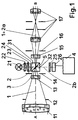
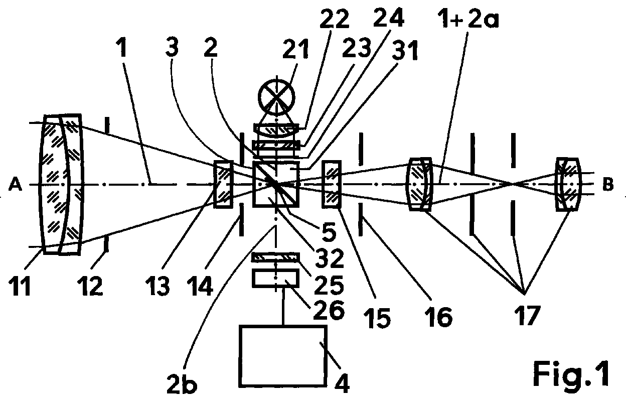
- FIG. 1 only the beam arrangement is used by the micropyrometer according to the invention and the associated evaluation device is shown symbolically. From Fig. 1 visible elements can all in one, not shown Pyrometer housing can be arranged - but it can be the so-called. Evaluation unit provide as an external unit.
- the main axis of the device runs from A to B and defines the observation beam path 1, which is crossed by a comparison beam path 2.
- a beam splitter In the intersection area of the two beam paths there is a beam splitter, generally numbered 3, which as geometric beam splitter "is executed.
- the beam splitter is 3 designed as a beam splitter cube. It consists of two prisms 31, 32, their Cathets at an angle of 90 ° to each other and preferably 45 ° each Form hypotenuse surface.
- the upper prism 31 is on the hypotenuse surface provided with a highly reflective comparison mark 5, in particular vaporized, and connected to the lower prism 32 to form a cube without bubbles, preferably cemented.
- the connecting means optical putty, adhesive
- bubble-free glass and optical putty with the same Refractive index like the preferred glass ensure that in addition to the Comparison mark 5 no further reflective objects or areas in the Beam splitter cube or in the beam splitter ball.
- the entrance and exit area of the Beam splitter cube in the direction of the optical axis A-B preferably with a effective anti-reflective coating.
- the comparison mark 5 is illuminated by the comparison light source 21, whose Light through the converging lens 22 (see FIG. 1) or one of the beam splitter cubes assigned lens part 22 '(see FIG. 3) in an approximately parallel bundle is converted.
- the predominant part of the The light beam from the comparative light source 21 strikes the photosensor 26.
- the calibration curve can be calculated - taking into account especially with the help of the Planck radiation formula of the spectral sensitivity curve of the photosensor 26.
- the elaborate characteristic curve calibration of the previous filament comparison lamps (Current, temperature characteristic) avoided. Instead, it is sufficient for Micropyrometer according to the invention in practice the adjustment at the beginning of the range or range end of each measuring range and possibly a small correction in the middle of the area (which can usually be omitted). The effort for that Pyrometer calibration is reduced to a minimum in the invention.
- the sensor signal is amplified in the amplification and linearization unit after ambient temperature compensation and emissivity correction in one temperature linear signal converted. This arrives via interfaces external peripheral devices such as Printer or computer, or it will be sent to the device's own display and control unit passed on, next to a display can also include input keys or input switches.
- the comparison marking 5 is preferably illuminated diffusely. It can however, the comparison mark 5 may also be designed to be diffusely reflective.
- a tubular lamp such as is preferably used as the comparative light source 21 it is used in car electronics and model making as inexpensive mass-produced goods.
- comparison spot design leaves one different design of the comparison spot. So compared to one Version with filament lamp the required comparison spot customer-specific be designed, e.g. as a line, V or angle illustration, cross, circle, point u. the like
Landscapes
- Physics & Mathematics (AREA)
- General Physics & Mathematics (AREA)
- Spectroscopy & Molecular Physics (AREA)
- Radiation Pyrometers (AREA)
- Devices For Conveying Motion By Means Of Endless Flexible Members (AREA)
- Crystals, And After-Treatments Of Crystals (AREA)
- Length Measuring Devices By Optical Means (AREA)
- Photometry And Measurement Of Optical Pulse Characteristics (AREA)
Abstract
Description
- Fig 1
- ein Aufbauprinzip (im Pyrometer-Längsschnitt) eines erfindungsgemäßen Mikropyrometers mit visuellem Intensitätsabgleich von Meßobjekt- und Vergleichsstrahlung sowie fotoelektrischer Messung der Vergleichsstrahlung,
- Fig 2
- eine vergrößerte Darstellung (in Seitenansicht) des im Kreuzungspunkt von Beobachtungsstrahlengang und Vergleichsstrahlengang angeordneten Strahlteilers in Form eines Strahlteilerwürfels, wobei eine mittige reflektierende Vergleichsmarkierung vorhanden ist und die vom Meßfleck einerseits und von einem geräteeigenen Vergleichsstrahler andererseits stammenden Lichtstrahlen aufgezeigt werden,
- Fig 3
- eine vergrößerte Seitenansicht eines abgeänderten Strahlteilerwürfels mit integriertem asphärischem Linsenteil zur näherungsweise parallelen Bündelung der Vergleichsstrahlung,
- Fig 4
- eine Seitenansicht eines abgeänderten, als Kugel ausgeführten Strahlteilers mit zwischen zwei schräg zur Vergleichsstrahlung angeordneten Trennflächen und auf einem derselben vorgesehenem Vergleichsfleck sowie
- Fig 5
- eine Draufsicht auf einen Strahlteiler in Rahmenkonstruktion mit von dünnen geschwärzten Haltestegen getragener Vergleichsmarkierung.
Claims (10)
- Pyrometer zur berührungslosen Temperaturmessung eines kleinen Meßflecks, mita) einem Objektiv und einem eine Vergrößerungsoptik aufweisenden Beobachtungsstrahlengang,b) einer in der Helligkeit durch den Bediener einstellbaren Vergleichslichtquelle,c) einer Einrichtung zur Beobachtung der Helligkeit von Vergleichs- und Meßobjektstrahlung sowie zum Helligkeitsabgleich der spektralen Strahlung von Meßobjekt und Vergleichslichtquelle - wobei zur Temperatur-Ermittlung ein visueller Intensitätsvergleich von voneinander abgegrenzten, benachbarten Bildzonen der spektralen Meßfleckstrahlung und Vergleichsstrahlung sowie eine Einstellung auf Helligkeitsgleichheit von Beobachtungsfeld und Vergleichsfeld durchführbar ist - sowied) einer bei oder nach erfolgtem Helligkeitsabgleich der Vergleichslichtquelle die Meßobjekttemperatur ermittelnden Auswerteeinrichtung,
dadurch gekennzeichnet, daßa) der Beobachtungsstrahlengang (1) vom Vergleichsstrahlengang (2) gekreuzt wird und im Kreuzungsbereich eine reflektierende Vergleichsmarkierung (5) angeordnet ist, die im Okular-Gesichtsfeld zusammen mit der Meßobjektstrahlung einsehbar ist,b) die geräteeigene Vergleichslichtquelle (21) von einer gewöhnlichen Glühlampe oder einer Leuchtdiode gebildet ist und einen in Transmissionsrichtung in zwei Lichtpfade (2a, 2b) aufgeteilten Vergleichsstrahlengang (2) beleuchtet, dessen erster Lichtpfad (2a) zur Vergrößerungsoptik (17) und dessen zweiter Lichtpfad (2b) zu einem Fotosensor (26) führt, undc) der Fotosensor (26) als eine die Strahlungsleistung der Vergleichslichtquelle (21) fotoelektrisch messende und - bei Helligkeitsgleichgewicht von Meßobjektstrahlung und Vergleichsstrahlung - ein temperaturbestimmendes Signal erzeugende Einrichtung ausgebildet ist sowie mit der Auswerteeinrichtung (4) verbunden ist. - Pyrometer nach Anspruch 1, dadurch gekennzeichnet, daß der optische Spektralbereich des Fotosensors (26) zur Messung der Vergleichslichtquelle (21) an den visuellen Spektralbereich des Beobachters angepaßt ist.
- Pyrometer nach Anspruch 1, dadurch gekennzeichnet, daß die Vergleichsmarkierung (5) als ein reflektierendes Muster in einem optisch transparenten Tragkörper eingebettet ist.
- Pyrometer nach Anspruch 3, dadurch gekennzeichnet, daß die Vergleichsmarkierung (5) auf einer Trennfläche eines zweigeteilten Strahlteilerwürfels aufgebracht, insbesondere aufgedampft, ist und die beiden Würfelhälften blasenfrei verbunden sind, wobei das Verbindungsmittel denselben Brechungsindex wie das Würfelmaterial aufweist.
- Pyrometer nach Anspruch 3, dadurch gekennzeichnet, daß die Vergleichsmarkierung (5) in einer zweigeteilten Strahlteilerkugel angeordnet ist, deren Kugelhälften blasenfrei verbunden sind, wobei das Verbindungsmittel denselben Brechungsindex wie das Kugelmaterial aufweist.
- Pyrometer nach Anspruch 1, dadurch gekennzeichnet, daß die Vergleichsmarkierung (5) als ein reflektierendes Muster auf der Oberfläche eines optisch transparenten, entspiegelten Tragkörpers, wie Platte, Folie od. dgl., angeordnet ist.
- Pyrometer nach Anspruch 1, dadurch gekennzeichnet, daß die Vergleichsmarkierung (5) von einer reflektierenden Strichmarkierung, mit einer Strichstärke von unter 0,1 mm Breite, gebildet ist.
- Pyrometer nach Anspruch 1, dadurch gekennzeichnet, daß die Vergleichsmarkierung (5) von einem reflektierenden Körper, wie Plättchen, Steg od. dgl., gebildet ist, welcher von einer reflektionsarmen Rahmenkonstruktion (33) mit dünnen Haltestegen (34) getragen wird.
- Pyrometer nach einem der Ansprüche 1 bis 8, dadurch gekennzeichnet, daß zwischen Vergleichslichtquelle (21) und Vergleichsmarkierung (5) eine das Vergleichslicht in ein näherungsweise paralleles Bündel umwandelnde Einrichtung, wie separate Sammellinse (22) oder Linsenteil (22') am Strahlteiler (3), vorgesehen ist.
- Pyrometer nach einem der Ansprüche 1 bis 9, dadurch gekennzeichnet, daß die Vergleichsmarkierung (5) diffus beleuchtet wird oder selbst diffus reflektierend ausgebildet ist.
Applications Claiming Priority (2)
| Application Number | Priority Date | Filing Date | Title |
|---|---|---|---|
| DE19808972 | 1998-03-04 | ||
| DE19808972 | 1998-03-04 |
Publications (3)
| Publication Number | Publication Date |
|---|---|
| EP0940660A2 true EP0940660A2 (de) | 1999-09-08 |
| EP0940660A3 EP0940660A3 (de) | 2001-03-28 |
| EP0940660B1 EP0940660B1 (de) | 2006-10-04 |
Family
ID=7859526
Family Applications (1)
| Application Number | Title | Priority Date | Filing Date |
|---|---|---|---|
| EP99104363A Expired - Lifetime EP0940660B1 (de) | 1998-03-04 | 1999-03-04 | Pyrometer |
Country Status (3)
| Country | Link |
|---|---|
| EP (1) | EP0940660B1 (de) |
| AT (1) | ATE341752T1 (de) |
| DE (1) | DE59913888D1 (de) |
Family Cites Families (3)
| Publication number | Priority date | Publication date | Assignee | Title |
|---|---|---|---|---|
| GB272799A (en) * | 1927-01-18 | 1927-06-23 | Rudolf Hase | An optical pyrometer |
| DE746401C (de) * | 1938-03-13 | 1944-08-01 | Peter Tracz | Optisches Pyrometer |
| GB636544A (en) * | 1947-02-01 | 1950-05-03 | Cecil Robert Barber | Improvements in or relating to optical pyrometers |
-
1999
- 1999-03-04 DE DE59913888T patent/DE59913888D1/de not_active Expired - Lifetime
- 1999-03-04 AT AT99104363T patent/ATE341752T1/de not_active IP Right Cessation
- 1999-03-04 EP EP99104363A patent/EP0940660B1/de not_active Expired - Lifetime
Also Published As
| Publication number | Publication date |
|---|---|
| EP0940660B1 (de) | 2006-10-04 |
| EP0940660A3 (de) | 2001-03-28 |
| ATE341752T1 (de) | 2006-10-15 |
| DE59913888D1 (de) | 2006-11-16 |
Similar Documents
| Publication | Publication Date | Title |
|---|---|---|
| EP1991450B1 (de) | Kameraanordnung für ein kraftfahrzeug | |
| DE19541233B4 (de) | Objekttisch für Mikroskope | |
| DE102013113265B4 (de) | Vorrichtung zur berührungslosen optischen Abstandsmessung | |
| DE19932202A1 (de) | Optoelektronische Meßeinrichtung zur Erfassung von Verbrennungsvorgängen | |
| EP0311561B1 (de) | Messkopf | |
| EP1815278A1 (de) | Fernrohr und panfokal-fernrohr mit plankonvex- oder plankonkavlinse und damit verbundenem umlenkmittel | |
| EP0886163B1 (de) | Strichplatte und optische Einrichtung mit einer beleuchtbaren Strichplatte | |
| DE3443728C2 (de) | Mikroskop-Photometer | |
| DE3877672T2 (de) | Linsensystem fuer infrarot-anwendungen. | |
| DE60131961T2 (de) | Verfahren zur bildgebenden Messung, bildgebende Messeinrichtung und Verwendung gemessener Informationen bei der Verfahrenssteuerung | |
| DE102009038028B4 (de) | Detektoranordnung mit erhöhter Empfindlichkeit durch Lichtablenkelemente mit einer ebenen Lichteintrittsfläche | |
| DE102017100720A1 (de) | Absehen und hiermit ausgestattetes Zielfernrohr, Schusswaffe hiermit und Verfahren zur Entfernungsbestimmung mit dem Absehen | |
| EP0940660A2 (de) | Pyrometer | |
| DE102007015896B4 (de) | Teleoptik für den infraroten Spektalbereich | |
| DE102010035041B4 (de) | Strahlungsthermometer | |
| DE19531536C2 (de) | Vorrichtung zur radiometrischen Kalibrierung von Infrarot-Meßgeräten | |
| EP0281518A2 (de) | Vermessungsinstrument | |
| EP0876637B1 (de) | Messeinrichtung für optische eigenschaften einer anzeige | |
| DE102016112750A1 (de) | Opto-elektronische Messeinrichtung für ein Farbmessgerät | |
| DE102005016414B3 (de) | Verfahren und Vorrichtung zur Messung der Temperaturstrahlung einer Meßfläche | |
| DE19828454A1 (de) | Vorrichtung und Verfahren zur Messung der Temperatur einer Zielfläche | |
| EP1656539B1 (de) | Radiometer, visiereinrichtung für ein ir-gerät sowie verfahren | |
| DE2461111A1 (de) | Hochaufloesendes apochromat | |
| DE102010035042B4 (de) | Strahlungsthermometer | |
| AT397153B (de) | Einrichtung zur immateriellen trefferbildanzeige |
Legal Events
| Date | Code | Title | Description |
|---|---|---|---|
| PUAI | Public reference made under article 153(3) epc to a published international application that has entered the european phase |
Free format text: ORIGINAL CODE: 0009012 |
|
| AK | Designated contracting states |
Kind code of ref document: A2 Designated state(s): AT BE CH CY DE DK ES LI |
|
| AX | Request for extension of the european patent |
Free format text: AL;LT;LV;MK;RO;SI |
|
| PUAL | Search report despatched |
Free format text: ORIGINAL CODE: 0009013 |
|
| AK | Designated contracting states |
Kind code of ref document: A3 Designated state(s): AT BE CH CY DE DK ES FI FR GB GR IE IT LI LU MC NL PT SE |
|
| AX | Request for extension of the european patent |
Free format text: AL;LT;LV;MK;RO;SI |
|
| RIC1 | Information provided on ipc code assigned before grant |
Free format text: 7G 01J 5/52 A, 7G 01J 5/08 B |
|
| RAP1 | Party data changed (applicant data changed or rights of an application transferred) |
Owner name: KELLER H.C.W. GMBH |
|
| RAP1 | Party data changed (applicant data changed or rights of an application transferred) |
Owner name: KELLER GMBH |
|
| AKX | Designation fees paid |
Free format text: AT BE CH CY DE DK ES LI |
|
| 19U | Interruption of proceedings before grant |
Effective date: 20001201 |
|
| 19W | Proceedings resumed before grant after interruption of proceedings |
Effective date: 20020625 |
|
| RAP1 | Party data changed (applicant data changed or rights of an application transferred) |
Owner name: KELLER H.C.W. GMBH |
|
| 17P | Request for examination filed |
Effective date: 20010929 |
|
| RBV | Designated contracting states (corrected) |
Designated state(s): AT BE CH CY DE DK ES FI FR GB GR IE IT LI LU MC NL PT SE |
|
| 17Q | First examination report despatched |
Effective date: 20050527 |
|
| GRAP | Despatch of communication of intention to grant a patent |
Free format text: ORIGINAL CODE: EPIDOSNIGR1 |
|
| GRAS | Grant fee paid |
Free format text: ORIGINAL CODE: EPIDOSNIGR3 |
|
| GRAA | (expected) grant |
Free format text: ORIGINAL CODE: 0009210 |
|
| AK | Designated contracting states |
Kind code of ref document: B1 Designated state(s): AT BE CH CY DE DK ES FI FR GB GR IE IT LI LU MC NL PT SE |
|
| PG25 | Lapsed in a contracting state [announced via postgrant information from national office to epo] |
Ref country code: NL Free format text: LAPSE BECAUSE OF FAILURE TO SUBMIT A TRANSLATION OF THE DESCRIPTION OR TO PAY THE FEE WITHIN THE PRESCRIBED TIME-LIMIT Effective date: 20061004 Ref country code: IT Free format text: LAPSE BECAUSE OF FAILURE TO SUBMIT A TRANSLATION OF THE DESCRIPTION OR TO PAY THE FEE WITHIN THE PRESCRIBED TIME-LIMIT;WARNING: LAPSES OF ITALIAN PATENTS WITH EFFECTIVE DATE BEFORE 2007 MAY HAVE OCCURRED AT ANY TIME BEFORE 2007. THE CORRECT EFFECTIVE DATE MAY BE DIFFERENT FROM THE ONE RECORDED. Effective date: 20061004 Ref country code: IE Free format text: LAPSE BECAUSE OF FAILURE TO SUBMIT A TRANSLATION OF THE DESCRIPTION OR TO PAY THE FEE WITHIN THE PRESCRIBED TIME-LIMIT Effective date: 20061004 Ref country code: FI Free format text: LAPSE BECAUSE OF FAILURE TO SUBMIT A TRANSLATION OF THE DESCRIPTION OR TO PAY THE FEE WITHIN THE PRESCRIBED TIME-LIMIT Effective date: 20061004 |
|
| REG | Reference to a national code |
Ref country code: GB Ref legal event code: FG4D Free format text: NOT ENGLISH |
|
| REG | Reference to a national code |
Ref country code: CH Ref legal event code: EP |
|
| REG | Reference to a national code |
Ref country code: IE Ref legal event code: FG4D Free format text: LANGUAGE OF EP DOCUMENT: GERMAN |
|
| REF | Corresponds to: |
Ref document number: 59913888 Country of ref document: DE Date of ref document: 20061116 Kind code of ref document: P |
|
| PG25 | Lapsed in a contracting state [announced via postgrant information from national office to epo] |
Ref country code: SE Free format text: LAPSE BECAUSE OF FAILURE TO SUBMIT A TRANSLATION OF THE DESCRIPTION OR TO PAY THE FEE WITHIN THE PRESCRIBED TIME-LIMIT Effective date: 20070104 Ref country code: DK Free format text: LAPSE BECAUSE OF FAILURE TO SUBMIT A TRANSLATION OF THE DESCRIPTION OR TO PAY THE FEE WITHIN THE PRESCRIBED TIME-LIMIT Effective date: 20070104 |
|
| PG25 | Lapsed in a contracting state [announced via postgrant information from national office to epo] |
Ref country code: ES Free format text: LAPSE BECAUSE OF FAILURE TO SUBMIT A TRANSLATION OF THE DESCRIPTION OR TO PAY THE FEE WITHIN THE PRESCRIBED TIME-LIMIT Effective date: 20070115 |
|
| PG25 | Lapsed in a contracting state [announced via postgrant information from national office to epo] |
Ref country code: PT Free format text: LAPSE BECAUSE OF FAILURE TO SUBMIT A TRANSLATION OF THE DESCRIPTION OR TO PAY THE FEE WITHIN THE PRESCRIBED TIME-LIMIT Effective date: 20070316 |
|
| NLV1 | Nl: lapsed or annulled due to failure to fulfill the requirements of art. 29p and 29m of the patents act | ||
| GBV | Gb: ep patent (uk) treated as always having been void in accordance with gb section 77(7)/1977 [no translation filed] |
Effective date: 20061004 |
|
| EN | Fr: translation not filed | ||
| REG | Reference to a national code |
Ref country code: IE Ref legal event code: FD4D |
|
| PLBE | No opposition filed within time limit |
Free format text: ORIGINAL CODE: 0009261 |
|
| STAA | Information on the status of an ep patent application or granted ep patent |
Free format text: STATUS: NO OPPOSITION FILED WITHIN TIME LIMIT |
|
| 26N | No opposition filed |
Effective date: 20070705 |
|
| REG | Reference to a national code |
Ref country code: CH Ref legal event code: PL |
|
| PG25 | Lapsed in a contracting state [announced via postgrant information from national office to epo] |
Ref country code: GB Free format text: LAPSE BECAUSE OF FAILURE TO SUBMIT A TRANSLATION OF THE DESCRIPTION OR TO PAY THE FEE WITHIN THE PRESCRIBED TIME-LIMIT Effective date: 20061004 |
|
| BERE | Be: lapsed |
Owner name: KELLER H.C.W. G.M.B.H. Effective date: 20070331 |
|
| PG25 | Lapsed in a contracting state [announced via postgrant information from national office to epo] |
Ref country code: BE Free format text: LAPSE BECAUSE OF NON-PAYMENT OF DUE FEES Effective date: 20070331 |
|
| PG25 | Lapsed in a contracting state [announced via postgrant information from national office to epo] |
Ref country code: MC Free format text: LAPSE BECAUSE OF NON-PAYMENT OF DUE FEES Effective date: 20070331 |
|
| PG25 | Lapsed in a contracting state [announced via postgrant information from national office to epo] |
Ref country code: LI Free format text: LAPSE BECAUSE OF NON-PAYMENT OF DUE FEES Effective date: 20070331 Ref country code: CH Free format text: LAPSE BECAUSE OF NON-PAYMENT OF DUE FEES Effective date: 20070331 |
|
| PG25 | Lapsed in a contracting state [announced via postgrant information from national office to epo] |
Ref country code: GR Free format text: LAPSE BECAUSE OF FAILURE TO SUBMIT A TRANSLATION OF THE DESCRIPTION OR TO PAY THE FEE WITHIN THE PRESCRIBED TIME-LIMIT Effective date: 20070105 Ref country code: FR Free format text: LAPSE BECAUSE OF FAILURE TO SUBMIT A TRANSLATION OF THE DESCRIPTION OR TO PAY THE FEE WITHIN THE PRESCRIBED TIME-LIMIT Effective date: 20070525 |
|
| PG25 | Lapsed in a contracting state [announced via postgrant information from national office to epo] |
Ref country code: AT Free format text: LAPSE BECAUSE OF NON-PAYMENT OF DUE FEES Effective date: 20070304 |
|
| PG25 | Lapsed in a contracting state [announced via postgrant information from national office to epo] |
Ref country code: FR Free format text: LAPSE BECAUSE OF FAILURE TO SUBMIT A TRANSLATION OF THE DESCRIPTION OR TO PAY THE FEE WITHIN THE PRESCRIBED TIME-LIMIT Effective date: 20061004 |
|
| PG25 | Lapsed in a contracting state [announced via postgrant information from national office to epo] |
Ref country code: LU Free format text: LAPSE BECAUSE OF NON-PAYMENT OF DUE FEES Effective date: 20070304 Ref country code: CY Free format text: LAPSE BECAUSE OF FAILURE TO SUBMIT A TRANSLATION OF THE DESCRIPTION OR TO PAY THE FEE WITHIN THE PRESCRIBED TIME-LIMIT Effective date: 20061004 |
|
| PGFP | Annual fee paid to national office [announced via postgrant information from national office to epo] |
Ref country code: DE Payment date: 20180119 Year of fee payment: 20 |
|
| REG | Reference to a national code |
Ref country code: DE Ref legal event code: R071 Ref document number: 59913888 Country of ref document: DE |