EP0940664A1 - Bündig montiertes und auf Entfernung anzubringendes Dichtungselement - Google Patents
Bündig montiertes und auf Entfernung anzubringendes Dichtungselement Download PDFInfo
- Publication number
- EP0940664A1 EP0940664A1 EP99103689A EP99103689A EP0940664A1 EP 0940664 A1 EP0940664 A1 EP 0940664A1 EP 99103689 A EP99103689 A EP 99103689A EP 99103689 A EP99103689 A EP 99103689A EP 0940664 A1 EP0940664 A1 EP 0940664A1
- Authority
- EP
- European Patent Office
- Prior art keywords
- disc
- diaphragm
- remote seal
- inner diameter
- sheet
- Prior art date
- Legal status (The legal status is an assumption and is not a legal conclusion. Google has not performed a legal analysis and makes no representation as to the accuracy of the status listed.)
- Withdrawn
Links
- 238000000034 method Methods 0.000 claims abstract description 51
- 239000000463 material Substances 0.000 claims abstract description 19
- 239000002184 metal Substances 0.000 claims abstract description 16
- 229910052751 metal Inorganic materials 0.000 claims abstract description 16
- 238000003466 welding Methods 0.000 claims abstract description 10
- 238000004519 manufacturing process Methods 0.000 claims abstract description 4
- 238000003754 machining Methods 0.000 claims description 12
- 238000002844 melting Methods 0.000 claims description 5
- 230000008018 melting Effects 0.000 claims description 5
- 238000005520 cutting process Methods 0.000 claims description 2
- 238000007789 sealing Methods 0.000 claims 2
- 239000007788 liquid Substances 0.000 claims 1
- 238000004886 process control Methods 0.000 abstract description 5
- 239000012530 fluid Substances 0.000 description 21
- 229910001220 stainless steel Inorganic materials 0.000 description 10
- 239000010935 stainless steel Substances 0.000 description 10
- 230000007797 corrosion Effects 0.000 description 9
- 238000005260 corrosion Methods 0.000 description 9
- 238000002955 isolation Methods 0.000 description 6
- 229910000856 hastalloy Inorganic materials 0.000 description 5
- 230000008878 coupling Effects 0.000 description 4
- 238000010168 coupling process Methods 0.000 description 4
- 238000005859 coupling reaction Methods 0.000 description 4
- DNIAPMSPPWPWGF-UHFFFAOYSA-N Propylene glycol Chemical compound CC(O)CO DNIAPMSPPWPWGF-UHFFFAOYSA-N 0.000 description 3
- 239000011888 foil Substances 0.000 description 3
- XLYOFNOQVPJJNP-UHFFFAOYSA-N water Substances O XLYOFNOQVPJJNP-UHFFFAOYSA-N 0.000 description 3
- PEDCQBHIVMGVHV-UHFFFAOYSA-N Glycerine Chemical compound OCC(O)CO PEDCQBHIVMGVHV-UHFFFAOYSA-N 0.000 description 2
- 239000000853 adhesive Substances 0.000 description 2
- 230000001070 adhesive effect Effects 0.000 description 2
- 238000005219 brazing Methods 0.000 description 2
- 238000010420 art technique Methods 0.000 description 1
- 238000010586 diagram Methods 0.000 description 1
- 230000000694 effects Effects 0.000 description 1
- 238000005516 engineering process Methods 0.000 description 1
- 235000011187 glycerol Nutrition 0.000 description 1
- 238000009434 installation Methods 0.000 description 1
- 238000005259 measurement Methods 0.000 description 1
- 239000007769 metal material Substances 0.000 description 1
- 150000002739 metals Chemical class 0.000 description 1
- 235000012771 pancakes Nutrition 0.000 description 1
- 229920001296 polysiloxane Polymers 0.000 description 1
- 229910000679 solder Inorganic materials 0.000 description 1
Images



Classifications
-
- G—PHYSICS
- G01—MEASURING; TESTING
- G01L—MEASURING FORCE, STRESS, TORQUE, WORK, MECHANICAL POWER, MECHANICAL EFFICIENCY, OR FLUID PRESSURE
- G01L19/00—Details of, or accessories for, apparatus for measuring steady or quasi-steady pressure of a fluent medium insofar as such details or accessories are not special to particular types of pressure gauges
- G01L19/06—Means for preventing overload or deleterious influence of the measured medium on the measuring device or vice versa
- G01L19/0627—Protection against aggressive medium in general
- G01L19/0645—Protection against aggressive medium in general using isolation membranes, specially adapted for protection
-
- G—PHYSICS
- G01—MEASURING; TESTING
- G01L—MEASURING FORCE, STRESS, TORQUE, WORK, MECHANICAL POWER, MECHANICAL EFFICIENCY, OR FLUID PRESSURE
- G01L19/00—Details of, or accessories for, apparatus for measuring steady or quasi-steady pressure of a fluent medium insofar as such details or accessories are not special to particular types of pressure gauges
- G01L19/0007—Fluidic connecting means
- G01L19/0046—Fluidic connecting means using isolation membranes
-
- Y—GENERAL TAGGING OF NEW TECHNOLOGICAL DEVELOPMENTS; GENERAL TAGGING OF CROSS-SECTIONAL TECHNOLOGIES SPANNING OVER SEVERAL SECTIONS OF THE IPC; TECHNICAL SUBJECTS COVERED BY FORMER USPC CROSS-REFERENCE ART COLLECTIONS [XRACs] AND DIGESTS
- Y10—TECHNICAL SUBJECTS COVERED BY FORMER USPC
- Y10T—TECHNICAL SUBJECTS COVERED BY FORMER US CLASSIFICATION
- Y10T29/00—Metal working
- Y10T29/49—Method of mechanical manufacture
- Y10T29/49826—Assembling or joining
- Y10T29/49877—Assembling or joining of flexible wall, expansible chamber devices [e.g., bellows]
Definitions
- the present invention relates to the process control industry. More specifically, the present invention relates to an isolation diaphragm or seal, of the type used to couple a process control instrument to a process.
- Some types of process control instruments such as pressure transmitters, have a pressure sensor which is fluidically coupled to an isolation diaphragm by a fill fluid.
- the isolation diaphragm comprises part of a subassembly called a "remote seal” or a “diaphragm seal” and isolates the pressure sensor from corrosive process fluids being sensed.
- Pressure is transferred from the isolation diaphragm to the sensor through the fill fluid which is substantially incompressible and fills cavities on both sides and a capillary tube (or thru-hole if the seal is directly mounted to the instrument).
- the tube is typically flexible and may extend for several meters.
- the process medium contacts the remote isolation diaphragm which conveys the exerted pressure to the pressure sensor disposed in the transmitter housing.
- the isolation diaphragm and any process-wetted parts of the remote seal are made of a corrosion resistant material such that the process medium does not damage the diaphragm.
- the housing of the remote seal may partially contact the process medium as well. Therefore, it is necessary that the housing of the remote seal be protected from contact with the process medium or otherwise be corrosion resistant.
- the prior art has attempted to protect the housing of the remote seal using a number of techniques.
- One type of prior art seal is known as an "extended seal" and includes a stainless steel tube welded to a stainless steel flange.
- a Hastelloy end cap which carries a Hastelloy diaphragm is welded to the stainless steel tube opposite the flange.
- a tubular sheet of Hastelloy fits over the stainless steel tube and is welded to the end cap.
- a disc of Hastelloy is banded to the flange and to the tubular sheet and covers the flange.
- the Hastelloy disc and the tubular sheet typically have a thickness of between 1/64 and 3/16 inches.
- such an extended seal requires sufficient room to accommodate the tube and may not be used in all installations.
- a method of manufacturing a remote seal of the type used in the process control industry includes welding a circular fusible metal sheet to a housing (flange).
- the sheet has a hole formed therein with an inner diameter.
- the method further includes attaching a diaphragm made of a metal to the sheet proximate to the inner diameter of the hole in the sheet.
- An apparatus in accordance with the present invention includes a remote seal having a housing and a fusible metal disc attached to the housing.
- the disc is of thin sheet metal and includes an inner and an outer diameter.
- the remote seal further includes a diaphragm attached to the disc along the inner diameter of the disc.
- the present invention is a flanged flush-diaphragm mount remote seal 12 (may be flanged-flush or "pancake style") which may be used with a transmitter 11 as shown in Figure 1.
- Remote seal 12 is connected to transmitter diaphragm in diaphragm 14.
- Remote seal 12 of the present invention includes a housing 17 which is protected from contact with process fluid 16 (as shown in Figure 1).
- the present invention provides reduced manufacturing and material costs in comparison with typical prior art techniques while allowing the placement of a machined gasket surface onto the seal.
- Remote seals are typically used in a number of instances with process instrumentation. For example, a remote seal can be used to protect the electronics and the sensors which are used in the transmitter from extremely hot, cold or corrosive process media.
- a remote seal may also be used to allow the pressure measuring device to be mounted remotely from the measurement point while keeping the process contained at the process connection. Additionally, remote seals may be used to sense pressures in viscous processes that would otherwise clog an instrument or
- Transmitter 11 measures the pressure of process medium 16.
- Remote seal 12 includes a thin flexible diaphragm 18 which contacts process medium 16.
- Seal 12 also includes backplate 19 which, together with diaphragm 18, define cavity 20.
- Capillary tube 22 couples cavity 20 to pressure sensor 28 disposed in transmitter housing 14, such coupling being made via transmitter housing diaphragm 25 and a sealed fluid system connecting diaphragm 25 with sensor 28.
- the sealed fluid system, as well as cavity 20 and capillary tube 22, is filled with a suitable fluid for transmitting the process pressure to sensor 28.
- the fluid may include silicone, oil, glycerin and water, propylene glycol and water, or any other suitable fluid which preferably is substantially incompressible.
- diaphragm 18 When process pressure is applied from process medium 16, diaphragm 18 displaces fluid, thereby transmitting the measured pressure from remote seal 12 through a passage in plate 19 and through tube 22 to pressure sensor 28.
- Sensor 28 can also operate on other known sensing principles, such as strain gauge technology.
- Circuitry within transmitter housing 14 electronically converts the capacitance into a linear 4-20 mA transmitter output signal over wire pair 30 related to the process pressure.
- Remote seal 12 is referred to as a "flanged flush-diaphragm seal".
- Diaphragm 18 is preferably fabricated of a material which is resistant to corrosion from the process fluid.
- one problem which the prior art has attempted to address is the corrosive effects of the process fluid on the seal housing 17 where remote seal 12 couples to process medium 16.
- FIG. 2A is a side cross-sectional view
- Figure 2B is a bottom plan view
- Figure 2C is a top plan view of a prior art remote seal 50.
- Remote seal 50 is referred to as a, "flanged-flush design” and includes seal housing 52.
- Remote seal 50 also includes a hydraulic fluid (fill fluid) fill port 54, an instrument connection 56, and a flexible diaphragm 58 which is welded by TIG weld 60.
- Surface 62 provided which is an annular shape and extends around diaphragm 58.
- Bolt holes 64 are used for coupling housing 52 to, for example, a tank filled with process fluid.
- housing 52 is formed from stainless steel and has a thickness of about 1 inch. Housing 52 is machined in a manner to be welded to the circular metal diaphragm 58. Gasket surface 62 is also machined on housing 52. Diaphragm 58 is typically a foil diaphragm that may be cut and formed with a die press.
- seal 50 shown in Figures 2A-C may be built out of stainless steel if seal 50 is not exposed to processes which are corrosive to stainless steel. If the process medium is capable of corroding stainless steel, the stainless steel housing 52 will be damaged and may leak process fluid. This problem may be overcome if the housing 52 is made from a corrosion resistant material, for example, the same material used to fabricate diaphragm 58. Thus, the process fluid will not damage body 52. However, this prior art embodiment is undesirable because the corrosion resistant material used to fabricate body 52 is relatively expensive and difficult to machine.
- Figure 3A is a side cross-sectional view of a prior art remote seal 100.
- Remote seal 100 includes housing 102, fill fluid connection 104 and instrument connection 106.
- Flexible diaphragm 108 has an outer diameter which is greater than the diameter of cavity 110 such that an overlap portion 112 of diaphragm 108 covers a portion of body 102 beyond the outer diameter of cavity 110.
- Figure 3B is an enlarged cross-sectional view of inset 114 shown in Figure 3A.
- Portion 112 is coupled to body 102 by a bonding material such as an adhesive 116 or through brazing 116, seam-welding, TIG welding or laser welding. Portion 112 thereby provides a gasket surface for coupling to a gasket.
- Portion 112 is fabricated of the same sheet of corrosion resistant material used to fabricate diaphragm 108 such that portion 112 protects housing 102 from corrosion due to process fluid.
- Diaphragm 108 and portion 112 are formed as an integral part out of the sheet of material.
- the material used to form diaphragm 108 and portion 112 is typically a foil between about 0.002 inches and about 0.004 inches thick.
- portion 112 may be damaged by contact with the gasket material. This can allow process fluid to leak past portion 112 and contact body 102 thereby leading to a process leak. This design also does not allow for a "machined" gasket surface, as the foil is too thin.
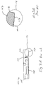
- Figure 4A is a side cross-sectional view and Figure 4B is a bottom plan view of a remote seal 130 in accordance with the present invention.
- Remote seal 130 includes housing (flange) 132 which typically comprises stainless steel fluid filling connection 134 and instrument connection 136.
- Bolt holes 138 are provided for coupling remote seal 130 to, for example, a standard ANSI flange on a process tank.
- Remote seal 130 also includes flexible diaphragm 140 which seals cavity 142 from the process side.
- a weld ring or disc 146 is provided and extends around the outer diameter of cavity 142.
- Disc 146 has an inner diameter which is substantially congruous with cavity 142 and diaphragm outer diameter.
- Figure 4C is an enlarged cross-sectional view of inset 150 shown in Figure 4A.
- Disc 146 provides a gasket surface which is adaptable to mate to a gasket 156 to thereby seal against a process flange.
- Disc 146 is preferably formed of a corrosion resistant material, for example, the same material used to fabricate diaphragm 140.
- Disc 146 is coupled to body 132 by welds 148.
- Welds 148 may comprise, for example, TIG welds.
- diaphragm 140 may be welded to disc 146, using TIG welds 152, for example.
- Disc 146 is preferably made out of sheet plate metal. However, disc 146 is sufficiently thin (between about 1/64" and 3/16") to substantially reduce material costs.
- a seal surface 157 of disc 146 is preferably machined in a manner to seal to gasket 156 when the remote seal is in operation. In one embodiment, the machining is performed after disc 146 is welded to housing 132. Further, a diaphragm lip or weld detail 160 is machined into disc 157 to accommodate the outer diameter of diaphragm 140.
- the inner and outer diameters of disc 146 are preferably machined using the same techniques. Such machining is preferably through direct cutting techniques in a lathe with several sheets affixed to a support fixture to allow them to be machined in the lathe without being crushed.
- Disc 146 may be formed from a thin piece of corrosion resistant material such as any "fusible metal" which is defined herein as comprising the Unified Numbering System metals: N10276; N06022; N10665; N06600; N02200; N04400; and N08020.
- the surface of disc 146 may be machined with a desired finish to interface with various gasket materials and industry standards.
- Disc 146 is preferably made of a fusible metal material which has a melting point which is within +/-300° F of the melting point of the housing 132.
Landscapes
- Physics & Mathematics (AREA)
- General Physics & Mathematics (AREA)
- Measuring Fluid Pressure (AREA)
Applications Claiming Priority (2)
| Application Number | Priority Date | Filing Date | Title |
|---|---|---|---|
| US33374 | 1998-03-02 | ||
| US09/033,374 US6038961A (en) | 1998-03-02 | 1998-03-02 | Flush mount remote seal |
Publications (1)
| Publication Number | Publication Date |
|---|---|
| EP0940664A1 true EP0940664A1 (de) | 1999-09-08 |
Family
ID=21870065
Family Applications (1)
| Application Number | Title | Priority Date | Filing Date |
|---|---|---|---|
| EP99103689A Withdrawn EP0940664A1 (de) | 1998-03-02 | 1999-02-25 | Bündig montiertes und auf Entfernung anzubringendes Dichtungselement |
Country Status (2)
| Country | Link |
|---|---|
| US (1) | US6038961A (de) |
| EP (1) | EP0940664A1 (de) |
Cited By (6)
| Publication number | Priority date | Publication date | Assignee | Title |
|---|---|---|---|---|
| DE102005004942A1 (de) * | 2005-02-02 | 2006-08-10 | Armaturenbau Gmbh | Verfahren zur Herstellung eines Mambran-Druckmittlers |
| WO2010033422A1 (en) * | 2008-09-17 | 2010-03-25 | P I Components Corporation | Diaphragm structure and method of manufacturing a diaphragm structure |
| CN101495846B (zh) * | 2006-03-23 | 2011-05-11 | 罗斯蒙德公司 | 冗余机械和电子遥控密封系统 |
| WO2018058487A1 (en) * | 2016-09-30 | 2018-04-05 | Rosemount Inc. | Process pressure transmitter with polymer seal |
| EP4163613A1 (de) * | 2021-10-08 | 2023-04-12 | Aquarius Spectrum Ltd. | System und verfahren zur befestigung und abdichtung von sensoren an rohren |
| US12320720B2 (en) | 2021-10-08 | 2025-06-03 | Aquarius Spectrum Ltd. | System and method for fixing and sealing sensors to pipes |
Families Citing this family (26)
| Publication number | Priority date | Publication date | Assignee | Title |
|---|---|---|---|---|
| US6203019B1 (en) * | 1999-03-31 | 2001-03-20 | The Babcock & Wilcox Company | Machine and method for preventing flange leakage |
| WO2002035197A2 (en) | 2000-10-24 | 2002-05-02 | Rosemount Inc. | Process connection for in-line pressure transmitter |
| US7080558B2 (en) * | 2003-10-06 | 2006-07-25 | Rosemount Inc. | Process seal for process control transmitter |
| US7117745B2 (en) * | 2004-02-09 | 2006-10-10 | Rosemount Inc. | Process seal for process control transmitter |
| US7377174B2 (en) * | 2004-03-18 | 2008-05-27 | Rosemount Inc. | Capillary weld extension with thermal isolation |
| US7096738B2 (en) * | 2004-03-18 | 2006-08-29 | Rosemount Inc. | In-line annular seal-based pressure device |
| US7430917B2 (en) * | 2006-04-10 | 2008-10-07 | Rosemount Inc. | Process transmitter with self sealing fill fluid system |
| US7454975B2 (en) * | 2007-04-06 | 2008-11-25 | Rosemount Inc. | Expansion chamber for use with a pressure transmitter |
| US8042401B2 (en) * | 2008-06-12 | 2011-10-25 | Rosemount, Inc. | Isolation system for process pressure measurement |
| US8214987B1 (en) | 2008-10-14 | 2012-07-10 | Jefferson Science Associates, Llc | Remote vacuum or pressure sealing device and method for critical isolated systems |
| US8015882B2 (en) * | 2009-06-04 | 2011-09-13 | Rosemount Inc. | Industrial process control pressure transmitter and flange coupling |
| JP5695796B2 (ja) | 2011-04-08 | 2015-04-08 | ローズマウント インコーポレイテッド | プロセス装置のための耐食性アイソレータアセンブリ |
| IN2014MN01663A (de) * | 2012-03-06 | 2015-05-29 | Rosemount Inc | |
| US9274018B2 (en) | 2012-09-28 | 2016-03-01 | Rosemount Inc. | Remote seal process pressure measuring system |
| US9442031B2 (en) | 2013-06-28 | 2016-09-13 | Rosemount Inc. | High integrity process fluid pressure probe |
| US9459170B2 (en) | 2013-09-26 | 2016-10-04 | Rosemount Inc. | Process fluid pressure sensing assembly for pressure transmitters subjected to high working pressure |
| US9103739B2 (en) | 2013-09-27 | 2015-08-11 | Rosemount Inc. | Seal for pressure transmitter for use in industrial process |
| CN110987283A (zh) | 2014-06-30 | 2020-04-10 | 罗斯蒙特公司 | 具有带类金刚石碳涂层的密封件的过程压力变送器 |
| US9752947B2 (en) * | 2014-09-23 | 2017-09-05 | P I Components Corp. | Thermoelectric heating, cooling and power generation for direct mount and dual compartment fill remote seal systems |
| US9752946B2 (en) * | 2014-09-23 | 2017-09-05 | Rosemount Inc. | Cooling for industrial process variable transmitters |
| US9638600B2 (en) | 2014-09-30 | 2017-05-02 | Rosemount Inc. | Electrical interconnect for pressure sensor in a process variable transmitter |
| US9772246B2 (en) | 2014-09-30 | 2017-09-26 | Rosemount Inc. | Fill fluid thermal management |
| EP3769063B1 (de) | 2018-05-17 | 2023-01-04 | Rosemount Inc. | Messelement und messvorrichtung damit |
| US11118989B2 (en) * | 2018-07-13 | 2021-09-14 | Rosemount Inc. | Process diaphragm seal |
| DE102021122224A1 (de) * | 2021-08-27 | 2023-03-02 | Endress+Hauser SE+Co. KG | Drucksensor, insbesondere für Drucke von mehr als 100 bar |
| US20240426688A1 (en) * | 2023-06-21 | 2024-12-26 | Rosemount Inc. | Process pressure transmitter for hydrogen applications |
Citations (3)
| Publication number | Priority date | Publication date | Assignee | Title |
|---|---|---|---|---|
| US4046010A (en) * | 1976-11-12 | 1977-09-06 | Beckman Instruments, Inc. | Pressure transducer with welded tantalum diaphragm |
| US4136603A (en) * | 1977-11-14 | 1979-01-30 | The Foxboro Company | Diaphragm assembly |
| US5230248A (en) * | 1991-07-12 | 1993-07-27 | Rosemount Inc. | Corrosion resistant isolator |
Family Cites Families (21)
| Publication number | Priority date | Publication date | Assignee | Title |
|---|---|---|---|---|
| US3072150A (en) * | 1959-11-03 | 1963-01-08 | American Radiator & Standard | Pressure-responsive device |
| US3675540A (en) * | 1968-07-19 | 1972-07-11 | Honeywell Inc | Diaphragm |
| JPS5233575A (en) * | 1975-09-09 | 1977-03-14 | Fuji Electric Co Ltd | Differential pressure measuring device |
| JPS5829862B2 (ja) * | 1977-05-14 | 1983-06-25 | 富士電機株式会社 | 圧力測定装置 |
| JPS5921497B2 (ja) * | 1978-11-02 | 1984-05-21 | 富士電機株式会社 | 圧力測定装置 |
| US4370890A (en) * | 1980-10-06 | 1983-02-01 | Rosemount Inc. | Capacitive pressure transducer with isolated sensing diaphragm |
| JPS58146827A (ja) * | 1982-02-25 | 1983-09-01 | Fuji Electric Co Ltd | 半導体式圧力センサ |
| JPS60234812A (ja) * | 1984-05-09 | 1985-11-21 | Fuji Kobunshi Kogyo Kk | ダイアフラムの製造方法 |
| US4872335A (en) * | 1985-10-25 | 1989-10-10 | Fuji Electric Co., Ltd. | Vibrating type transducer |
| US4787250A (en) * | 1987-04-23 | 1988-11-29 | Honeywell Inc. | Method of producing a uniform fluid-tight seal between a thin, flexible member and a support and an apparatus utilizing the same |
| US4833922A (en) * | 1987-06-01 | 1989-05-30 | Rosemount Inc. | Modular transmitter |
| JP2570420B2 (ja) * | 1988-06-23 | 1997-01-08 | 富士電機株式会社 | 静電容量式圧力検出器 |
| JP2639159B2 (ja) * | 1989-04-14 | 1997-08-06 | 富士電機株式会社 | 静電容量式差圧検出器 |
| US5094109A (en) * | 1990-12-06 | 1992-03-10 | Rosemount Inc. | Pressure transmitter with stress isolation depression |
| KR0163443B1 (ko) * | 1991-07-04 | 1999-03-30 | 나까오 다께시 | 압력측정장치 |
| US5184514A (en) * | 1991-07-12 | 1993-02-09 | Rosemount Inc. | Corrosion resistant isolator |
| JPH05149814A (ja) * | 1991-11-29 | 1993-06-15 | Fuji Electric Co Ltd | 二重ダイヤフラム式半導体圧力センサ |
| EP0607482B1 (de) * | 1993-01-20 | 1997-05-07 | WIKA ALEXANDER WIEGAND GmbH & CO. | Druckmittler |
| DE69417247T2 (de) * | 1993-09-24 | 1999-07-08 | Rosemount Inc., Eden Prairie, Minn. | Drucküberträger mit isoliermembran |
| JP3166477B2 (ja) * | 1994-05-10 | 2001-05-14 | 富士電機株式会社 | 差圧検出装置 |
| CZ269697A3 (cs) * | 1995-02-28 | 1998-06-17 | Rosemount Inc. | Zařízení pro měření pracovního tlaku |
-
1998
- 1998-03-02 US US09/033,374 patent/US6038961A/en not_active Expired - Lifetime
-
1999
- 1999-02-25 EP EP99103689A patent/EP0940664A1/de not_active Withdrawn
Patent Citations (3)
| Publication number | Priority date | Publication date | Assignee | Title |
|---|---|---|---|---|
| US4046010A (en) * | 1976-11-12 | 1977-09-06 | Beckman Instruments, Inc. | Pressure transducer with welded tantalum diaphragm |
| US4136603A (en) * | 1977-11-14 | 1979-01-30 | The Foxboro Company | Diaphragm assembly |
| US5230248A (en) * | 1991-07-12 | 1993-07-27 | Rosemount Inc. | Corrosion resistant isolator |
Non-Patent Citations (1)
| Title |
|---|
| JAQUITH H R: "IMPROVED DESIGN AND MOUNTING OF REMOTE SEAL LIQUID LEVEL TRANSMITTERS", ADVANCES IN INSTRUMENTATION AND CONTROL, vol. 47, no. PART 02, 1 January 1992 (1992-01-01), pages 1149 - 1160, XP000328949 * |
Cited By (13)
| Publication number | Priority date | Publication date | Assignee | Title |
|---|---|---|---|---|
| DE102005004942A1 (de) * | 2005-02-02 | 2006-08-10 | Armaturenbau Gmbh | Verfahren zur Herstellung eines Mambran-Druckmittlers |
| DE102005004942B4 (de) * | 2005-02-02 | 2014-10-02 | Armaturenbau Gmbh | Verfahren zur Herstellung eines Membran-Druckmittlers |
| CN101495846B (zh) * | 2006-03-23 | 2011-05-11 | 罗斯蒙德公司 | 冗余机械和电子遥控密封系统 |
| WO2010033422A1 (en) * | 2008-09-17 | 2010-03-25 | P I Components Corporation | Diaphragm structure and method of manufacturing a diaphragm structure |
| US7814798B2 (en) | 2008-09-17 | 2010-10-19 | P I Components Corporation | Diaphragm structure and method of manufacturing a diaphragm structure |
| CN102159928B (zh) * | 2008-09-17 | 2013-06-05 | 匹艾器件有限公司 | 膜片结构和制造膜片结构的方法 |
| WO2018058487A1 (en) * | 2016-09-30 | 2018-04-05 | Rosemount Inc. | Process pressure transmitter with polymer seal |
| CN108603798A (zh) * | 2016-09-30 | 2018-09-28 | 艾默生(北京)仪表有限公司 | 具有聚合物密封件的过程压力变送器 |
| US10378984B2 (en) | 2016-09-30 | 2019-08-13 | Rosemount Inc. | Process pressure transmitter with polymer seal |
| RU2719321C1 (ru) * | 2016-09-30 | 2020-04-17 | Роузмаунт Инк. | Преобразователь технологического давления с полимерной мембраной |
| CN116124355A (zh) * | 2016-09-30 | 2023-05-16 | 罗斯蒙特公司 | 具有聚合物密封件的过程压力变送器 |
| EP4163613A1 (de) * | 2021-10-08 | 2023-04-12 | Aquarius Spectrum Ltd. | System und verfahren zur befestigung und abdichtung von sensoren an rohren |
| US12320720B2 (en) | 2021-10-08 | 2025-06-03 | Aquarius Spectrum Ltd. | System and method for fixing and sealing sensors to pipes |
Also Published As
| Publication number | Publication date |
|---|---|
| US6038961A (en) | 2000-03-21 |
Similar Documents
| Publication | Publication Date | Title |
|---|---|---|
| US6038961A (en) | Flush mount remote seal | |
| EP0965829B1 (de) | Isoliermembranmontage | |
| EP2379997B1 (de) | Membranstruktur und verfahren zur herstellung einer membranstruktur | |
| US4046010A (en) | Pressure transducer with welded tantalum diaphragm | |
| CA1119839A (en) | Diaphragm seal assembly | |
| US5184514A (en) | Corrosion resistant isolator | |
| CA2953804C (en) | Process pressure transmitter with seal having diamond like carbon coating | |
| US8915140B2 (en) | Corrosion resistant isolator assembly for process devices | |
| EP4220110B1 (de) | Prozessdruckwandler mit polymerdichtung | |
| JP2005524847A (ja) | 圧力センサ組立体 | |
| CA2145696A1 (en) | Pressure sensor assembly and method of producing the pressure sensor assembly | |
| US7866214B2 (en) | Pressure gauge with hydraulic pressure transmission | |
| JPS63144228A (ja) | 差圧・圧力発信器 |
Legal Events
| Date | Code | Title | Description |
|---|---|---|---|
| PUAI | Public reference made under article 153(3) epc to a published international application that has entered the european phase |
Free format text: ORIGINAL CODE: 0009012 |
|
| AK | Designated contracting states |
Kind code of ref document: A1 Designated state(s): AT BE CH CY DE DK ES FI FR GB GR IE IT LI LU MC NL PT SE |
|
| AX | Request for extension of the european patent |
Free format text: AL;LT;LV;MK;RO;SI |
|
| AKX | Designation fees paid | ||
| REG | Reference to a national code |
Ref country code: DE Ref legal event code: 8566 |
|
| STAA | Information on the status of an ep patent application or granted ep patent |
Free format text: STATUS: THE APPLICATION IS DEEMED TO BE WITHDRAWN |
|
| 18D | Application deemed to be withdrawn |
Effective date: 20000309 |