EP0940735A2 - Oberflächenpflegemaschine mit computergesteuerten Betriebs- und Wartungssystemen - Google Patents
Oberflächenpflegemaschine mit computergesteuerten Betriebs- und Wartungssystemen Download PDFInfo
- Publication number
- EP0940735A2 EP0940735A2 EP99300138A EP99300138A EP0940735A2 EP 0940735 A2 EP0940735 A2 EP 0940735A2 EP 99300138 A EP99300138 A EP 99300138A EP 99300138 A EP99300138 A EP 99300138A EP 0940735 A2 EP0940735 A2 EP 0940735A2
- Authority
- EP
- European Patent Office
- Prior art keywords
- machine
- maintenance
- brush
- operator
- scrub
- Prior art date
- Legal status (The legal status is an assumption and is not a legal conclusion. Google has not performed a legal analysis and makes no representation as to the accuracy of the status listed.)
- Granted
Links
Images

Classifications
-
- G—PHYSICS
- G05—CONTROLLING; REGULATING
- G05B—CONTROL OR REGULATING SYSTEMS IN GENERAL; FUNCTIONAL ELEMENTS OF SUCH SYSTEMS; MONITORING OR TESTING ARRANGEMENTS FOR SUCH SYSTEMS OR ELEMENTS
- G05B19/00—Program-control systems
- G05B19/02—Program-control systems electric
- G05B19/04—Program control other than numerical control, i.e. in sequence controllers or logic controllers
- G05B19/042—Program control other than numerical control, i.e. in sequence controllers or logic controllers using digital processors
- G05B19/0428—Safety, monitoring
Definitions
- “Surface maintenance machines” broadly encompasses machines which will sweep an area such as a factory floor, hallway or the like, and machines which will perform a scrubbing function in that same environment. Surface maintenance machines also are designed to perform both scrubbing and sweeping functions. In the latter type of machine there are a number of specific functions that the operator must control in order to do a proper job. The operator must raise and lower the sweeping brush; raise and lower the scrubbing brush; raise and lower the squeegee to remove used cleaning solution and direct that solution to the recovery tank; control the speed and direction of the machine; and periodically clean the filter in the dust collection system and dump the debris hopper.
- the present invention is designed specifically to provide multi-function control buttons which are positioned about a graphics display panel. Images on the display panel identify the current function of the peripheral buttons and these functions will change as the operator moves through different control and maintenance options.
- the intent of the present control system is to offer simplified control of sweeping and scrubbing, while reducing the number of controls confronting the operator. This is accomplished by using multi-function buttons in which the operator is only offered control of the functions which are appropriate for a specific task.
- the operator also has a menu button which allows him to scroll through the various operating and maintenance functions.
- the invention will be described in connection with a machine which combines both scrubbing and sweeping functions.
- the concepts disclosed are equally applicable to a machine which only scrubs or only sweeps and it is broadly directed to a surface maintenance machine.
- the operator is precluded from directing the machine to perform certain functions if the conditions to perform that function are not determined by sensors on the machine to be appropriate. For example, if the operator is using the machine in a sweeping mode, the hopper door is automatically open. It would be inappropriate for the operator to close the door while sweeping and so none of the multi-function buttons or switches are assigned to the hopper door when the machine is in a sweeping mode. On the other hand, if the operator directs the machine to lift the hopper, then the operator will have control of the hopper door.
- the microprocessor which receives input information from sensors, from the operator control buttons, and provides the signals to the various operating systems on the machine for both operation and maintenance purposes is programmed to assist the operator in both operating and maintaining the machine, but prevents the operator from directing the machine to perform functions which would be inappropriate considering a particular mode of operation.
- the present invention relates to surface maintenance machines such as scrubbers, sweepers and combination machines which both sweep and scrub and more particularly relates to a simplified operator control system for both using the machine in its conventional cleaning tasks and providing maintenance for the machine at predetermined maintenance levels.
- a primary purpose of the invention is a simplified computerized operator control system for a surface maintenance machine of the type described.
- Another purpose is a surface maintenance machine having simplified operator controls including a graphic display screen and a plurality of multi-function buttons which function in cooperation with sensors on the machine to provide operator control of both operation and maintenance.
- Another purpose is a surface maintenance machine as described which has sensors for determining machine operating parameters and operator control buttons, both connected to a central processing unit, with the processing unit issuing commands to operate the machine as determined by the operator when preconditions determined by the sensors have been met.
- Another purpose is a surface maintenance machine operation and maintenance control system which provides for readjustment of maintenance time periods as determined by the actual elapsed time periods between maintenance functions.
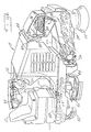
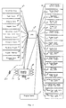
- Fig. 1 diagrammatically illustrates a combination machine of this type and Fig. 2 illustrates the control system for it in block diagram form.
- the several tables included in the application describe the control system for both operational and maintenance functions in a simplified outline form and should be considered in connection with the block diagram of Fig. 2 and the machine illustration of Fig. 1.
- the surface maintenance machine 10 has a driver's seat 12 and the driver will have a control panel 14, a portion of which is illustrated in Fig. 2 as including a graphic display 16, a plurality of multi-function buttons 18, there being six in the example illustrated herein, and a menu control button 20.
- a light emitting diode (LED) 19 will be adjacent each button.
- the buttons 18 are at the periphery or along both sides of the display 16 and will each be associated with a particular display sector of the screen as exemplified by Figs. 3A through 3D.
- the display, the multi-function control buttons with their associated LEDs, the menu button and the key switch collectively comprise what is commonly referred to as the "front panel. "
- the machine 10 will have a drive motor, controlled by the operator to drive the machine in both forward and reverse directions. There are front wheels 22 and rear wheels 24.
- the machine has a sweeping brush 26 which will direct debris into a hopper 28.
- a vacuum fan 30 which path extends through the hopper 28, through a baffle 32, and then through a filter 34.
- the filter 34 may include a shaker 36 which functions to shake the filter so as to clean it when the need arises.
- the hopper 28 has a hopper door 38 attached to the hopper with a hinge 39. The door will be open as shown in Fig. 1 during sweeping and will be swung down to close off the entrance opening of the hopper when the hopper is raised for dumping purposes.
- the dumping mechanism is illustrated in part by the arms 40 which will be used to hydraulically lift the hopper with the door closed and rotate it so the door is at the bottom. Then the door may be opened to dump the debris therein into a suitable refuse container.
- a side brush 42 which will function to direct dust and debris toward the main sweeping brush 26 so as to clear the area adjacent the side of the machine and to direct debris from the side of the machine, through the brush 26, into the hopper 28.
- the machine also has scrubbing capability, and for this purpose it has a pair of rotatable scrub brushes 44, which are raised and lowered by a mechanism 46 which will be under the control of the operator.
- a mechanism 46 which will be under the control of the operator.
- the operator may adjust the down pressure or the force that the scrub brushes apply to the underlying surface to be cleaned.
- the scrub brushes may be centered on the machine, or on occasion they may be moved out somewhat to one side for edge scrubbing along a wall.
- a squeegee 48 at the rear of the machine.
- the squeegee will vacuum up soiled cleaning solution and direct it through a conduit 50 to a soiled cleaning solution or recovery tank 52.
- a vacuum fan 53 draws air from the recovery tank to vacuumize conduit 50.
- Cleaning solution is supplied to the brushes 44 through a hose 54 which will dispense cleaning solution from a clean water tank 55 in which water is mixed with a suitable detergent.
- the surface maintenance machine 10 will thus include a drive for moving the machine at varying speeds in forward and reverse directions and a sweeping brush to direct debris into a hopper, with the hopper having a door and the hopper being capable of being raised and lowered to dump the debris therein.
- There is a path for dust control air through the hopper which path includes a filter, and there are means for shaking or cleaning the filter.
- the scrubbing portion of the machine includes scrub brushes, which may be raised and lowered, and which may have their down pressure adjusted.
- There is a squeegee which vacuums the dirty cleaning solution and sends it to a recovery tank.
- the recovery tank may be of the type which recycles the soiled solution and returns it, at least in part, by pump 57 and conduit 59 to the clean water 55 tank from whence cleaning solution is dispensed to the area of the brushes.
- a central processing unit (CPU) is indicated at 60 and it will contain a microprocessor programmed to perform the functions described hereinafter.
- the CPU 60 receives inputs from the graphic display and from the operator control buttons 18 and 20. These are commands to the CPU to perform certain functions.
- the machine has a plurality of sensors illustrated in boxes 62 through 80, with these sensors monitoring solution flow, fuel level, engine temperature, hopper position, solution tank level, recovery tank level, forward propulsion, reverse propulsion, hopper temperature, and the condition or cleanliness of the filter 34. Each of these sensors provides an input to CPU 60 and the sensor outputs create preconditions or qualifications for functions to be performed in response to commands from CPU 60.
- the outputs from CPU 60 go to boxes 82 through 118, with the outputs commanding certain functions to be initiated to operate the surface maintenance machine.
- the functions are designated as Scrub head (Lift, Lower); Scrub Brush (on, off); Squeegee (Lift, Lower); Scrub fan (on, off); Sweep fan (on, off); Sweep Head (lift, lower); Sweep brush (on, off); Hopper door (open, close); Sweep Fan (on, off); Filter shaker (on, off); Side Brush (lift, lower); Side Brush (on, off); ES (extended scrub) pump (on, off); Edge Scrub (in, out); Scrub Solution (on, off); Detergent pump (high, low, off); Solution tank fill (on, off); Recovery tank fill (on, off); and Engine Speed.
- the operator has six multi-function buttons and a menu button and in cooperation with a microprocessor which is suitably programmed to react to the inputs from the designated sensors, the operator is able to control all of the designated functions of the surface maintenance machine.
- Figs. 3A through 3D are illustrative of the type of icons which may appear on the display screen 16 in response to the operator successively pushing menu button 20, and which will indicate to the operator what operational functions are available.
- Fig. 3A is the idle screen and gives the operator the choice of selecting sweep, scrub and water pickup functions. The screen also indicates fuel status and time.
- Fig. 3B is the scrub screen and this screens adds extended scrub (ES), detergent pump and edge scrub functions to the basic idle screen.
- ES extended scrub
- ES function refers to Extended Scrub operation, which is a Tennant Company registered trademark for recycling scrubbing solution recovered from the floor through a filter and back to the clean solution tank for re-use, a method for prolonging the time a machine can scrub between refills of scrubbing solution.
- the screen of Fig. 3C is the sweep screen and adds the dust control vacuum fan, side brush and filter shaker functions to the idle screen.
- the screen in Fig. 3D is the hopper up or dump screen and this screen is activated when the hopper is lifted. It gives the operator the ability to open the hopper door and shake the filter.
- Table 1 illustrates the front panel operating modes and is essentially self-explanatory.
- the menu button In every instance in both Tables 1 and 2 in which the column 2 entry indicates an operation of the "logo" key, this is the menu button.
- the company logo surrounds the menu button and hence the button is designated as the logo key.
- the operator has a choice of an idle mode, a scrub mode, a sweep mode, a hopper up mode and a sweep/scrub mode.
- the entry sequence for the operator to a particular mode is shown in the second column; the functions available to the operator in that mode are shown in the third column; and the fourth column provides a description of what functions the operator may utilize in a particular mode.
- the operator may always use the menu button to cycle through the various options which are available.
- Idle Mode 1 This is the mode in which the panel will normally power up.
- Scrub The mode gives the operator the basic, sweep, scrub and water pickup modes. 2. No function 3. Squeegee 4. Sweep 5. No function 6. No function Scrub Mode 1. Pressing the scrub button from the idle mode. 1. Scrub This mode gives the operator control of all scrub functions. 2. Edge scrub 3. Squeegee 2. Pressing the logo button from the idle mode. 4. Sweep 5. Detergent Metering 6. ES function Sweep Mode 1. Pressing the sweep button from the idle mode. 1. Scrub This mode gives the operator control of all sweep functions. 2. Filter shaker 3. Squeegee 2. Pressing the logo button from the scrub mode. 4. Sweep 5.
- Sweep fan Hopper up Mode Lifting the hopper (releasing the hopper down switch). 1. Scrub This mode gives the operator control of the hopper door. 2. Filter shaker 3. Squeegee 4. No function 2. Pressing the logo button from the sweep mode. 5. No function 6. Hopper door Sweep/Scrub Mode 1. Pressing the scrub button while in the sweep mode. 1. Scrub This gives the operator control of the primary sweep controls, and three primary scrub controls. 2. Edge scrub 3. Squeegee 2. Pressing the sweep button while in the scrub mode 4. Sweep 5. Side brush 6. Sweep fan Hopper up Mode 1. Lifting the hopper (releasing the hopper down switch). 1. Scrub This mode gives the operator control of the hopper door. 2. Filter shaker 3. Squeegee 4. No function 2. Pressing the logo button from the sweep mode. 5. No function 6. Hopper door Sweep/Scrub Mode 1. Pressing the scrub button while in the sweep mode. 1. Scrub This gives the operator control of the primary sweep controls, and three primary scrub controls. 2. Edge scrub 3.
- Table 2 illustrates the various maintenance modes which are available to the operator. Again, the first column indicates the mode; the second column the entry sequence for the operator to enter that mode; the third column details the functions available at each of the six buttons in a specific mode; and the fourth column describes what the operator may do in a particular maintenance mode.
- Input Display Mode Select the Input Display mode from the Maintenance 2 screen. Display the state of floats, limit switches, and sensors. This mode enables a special display that indicates the various float and input switch levels. The operator can operate the machine in input display mode by scrolling to the operating modes, engaging the desired functions, and scrolling back to the input display mode. Self test mode.
- Pressure Adjust Mode Select the pressure adjust mode from the Maintenance 1 screen.
- Scrub function Adjust pressure levels for the three down pressure settings. The level of current flowing to the valve is represented by a bar graph on the display. The neutral headlift feature is disabled in the Pressure adjust mode. 2. No function 3. Squeegee function. 4. Increase brush pressure 5. No function 6. Decrease brush pressure.
- Reset Scrub Pressures Select the reset function from the maintenance 1 screen. 1. No function Return the down pressure settings to the factory defaults. 2. Reset down pressures 3. Do not reset down pressures, exit. 4. No function 5. No function 6. No function Adjust Time Mode Select Adjust Time from Maintenance 2 screen. 1. Increment segment Set the on board clock and calendar. 2. Decrement segment 3.
- the sensors indicate to the CPU the conditions of the machine and certain conditions must be satisfied before certain functions can be performed. For example, and as described above, the operator has no control of the hopper door if the machine is in a sweeping function. The operator only has control of the hopper door if the operator has the machine in a hopper up mode for dumping it.
- the maintenance modes are set forth in Table 2 and when the machine is in a check maintenance mode, which is a function reached by button #2 in the maintenance 3 mode, the screen will give the operator an indication of how many actual operating minutes or hours have elapsed since the last service reminder for a particular service function. For example, at 50 hours the engine oil should be changed; at 100 hours, the coolant system should be flushed; at 200 hours the chassis of the machine should be greased. At 400 hours there should be an engine tune-up; and at 800 hours there should be a change in the hydraulic fluid in the machine. There are certain times when the brushes should be changed in order to insure proper sweeping and scrubbing. These elapsed times are indicated in the check maintenance mode.
- the sensors will indicate to the CPU when a particular maintenance item has been accomplished. Assuming the maintenance is performed at the scheduled time interval, the CPU will retain that interval as the time period for a particular maintenance function. However, if the maintenance is performed either substantially earlier or substantially after the required time period, the CPU will recalculate the maintenance interval for a particular maintenance item. For example, assume a brush is to be changed after 50 hours of operation, and for brush operation to be logged, certain preconditions must be met; that is, the machine must be moving at the required speed and the brush must be turning. If, however, the brush is changed at 30 hours, the maintenance interval may change from 50 hours to 40 hours, which is an average of the actual elapsed time and the programmed elapsed maintenance time for that particular item.
- the present invention provides a sweeping and scrubbing machine which is designed to offer operator control of only functions which are appropriate for a current task.
- the intent is to reduce the number of controls confronting the operator and this is accomplished by using multi-function buttons along with the light emitting diodes (LEDs) which are positioned next to the buttons and which provide additional indications to the operator.
- Each of the buttons is adjacent a particular display sector of the graphic screen 16 and is associated with that part of the screen such that pressing of a particular button will cause the function illustrated by the icon next to the button to be performed.
Landscapes
- Physics & Mathematics (AREA)
- General Physics & Mathematics (AREA)
- Engineering & Computer Science (AREA)
- Automation & Control Theory (AREA)
- Cleaning In General (AREA)
- Control Of Position, Course, Altitude, Or Attitude Of Moving Bodies (AREA)
Applications Claiming Priority (2)
| Application Number | Priority Date | Filing Date | Title |
|---|---|---|---|
| US09/007,669 US5940928A (en) | 1998-01-15 | 1998-01-15 | Surface maintenance machine with computer controlled operational and maintenance systems |
| US7669 | 1998-01-15 |
Publications (3)
| Publication Number | Publication Date |
|---|---|
| EP0940735A2 true EP0940735A2 (de) | 1999-09-08 |
| EP0940735A3 EP0940735A3 (de) | 2002-02-06 |
| EP0940735B1 EP0940735B1 (de) | 2007-09-05 |
Family
ID=21727493
Family Applications (1)
| Application Number | Title | Priority Date | Filing Date |
|---|---|---|---|
| EP99300138A Expired - Lifetime EP0940735B1 (de) | 1998-01-15 | 1999-01-08 | Oberflächenpflegemaschine mit computergesteuerten Betriebs- und Wartungssystemen |
Country Status (3)
| Country | Link |
|---|---|
| US (1) | US5940928A (de) |
| EP (1) | EP0940735B1 (de) |
| DE (1) | DE69937015T2 (de) |
Cited By (12)
| Publication number | Priority date | Publication date | Assignee | Title |
|---|---|---|---|---|
| US6640386B2 (en) | 2001-09-18 | 2003-11-04 | The Hoover Company | Floor cleaning unit with a brush assembly |
| US6832409B2 (en) | 2001-09-18 | 2004-12-21 | The Hoover Company | Wet/dry floor cleaning unit and method of cleaning |
| EP1593334A2 (de) | 2004-04-30 | 2005-11-09 | Alfred Kärcher GmbH & Co. KG | Fahrbare Bodenreinigungsmaschine |
| EP1595487A1 (de) * | 2004-05-11 | 2005-11-16 | Comac S.p.A. | Bodenreinigungsmaschine, insbesondere für industrielle Anwendungen |
| US7254864B2 (en) | 2004-07-01 | 2007-08-14 | Royal Appliance Mfg. Co. | Hard floor cleaner |
| CN106214075A (zh) * | 2016-07-28 | 2016-12-14 | 江苏铂英特电子科技有限公司 | 一种用于地面清洁的自动清洁装置 |
| CN106214077A (zh) * | 2016-07-28 | 2016-12-14 | 江苏铂英特电子科技有限公司 | 一种用于地面清洁的自动清洁设备 |
| CN106535730A (zh) * | 2014-03-24 | 2017-03-22 | 国邦清洁设备控股有限公司贸易用名国邦清洁设备 | 具有智能系统的地板清洁机器 |
| CN110881908A (zh) * | 2019-12-14 | 2020-03-17 | 陈志后 | 一种基于自由度数的盘架角距弧啮的扫地机械机器人 |
| EP2925462B1 (de) * | 2012-11-30 | 2020-07-01 | Tennant Company | Dynamisches instandhaltungsplanungssystem für oberflächenreinigungsmaschinen |
| US12075957B2 (en) | 2014-03-24 | 2024-09-03 | Intelligent Cleaning Equipment Holdings Co. Ltd. | Floor cleaning machines having intelligent systems, associated sub-assemblies incorporating intelligent systems, and associated methods of use |
| WO2025199013A1 (en) * | 2024-03-18 | 2025-09-25 | Tennant Company | Surface maintenance machines having visual indicia for maintenance intervals |
Families Citing this family (36)
| Publication number | Priority date | Publication date | Assignee | Title |
|---|---|---|---|---|
| AU772590B2 (en) * | 1999-06-08 | 2004-04-29 | Diversey, Inc. | Floor cleaning apparatus |
| US8788092B2 (en) | 2000-01-24 | 2014-07-22 | Irobot Corporation | Obstacle following sensor scheme for a mobile robot |
| US8412377B2 (en) | 2000-01-24 | 2013-04-02 | Irobot Corporation | Obstacle following sensor scheme for a mobile robot |
| US6421870B1 (en) | 2000-02-04 | 2002-07-23 | Tennant Company | Stacked tools for overthrow sweeping |
| US6357070B1 (en) * | 2000-02-16 | 2002-03-19 | Windsor Industries, Inc. | Multi-function, battery-powered, rider cleaning machine |
| US8051861B2 (en) | 2001-07-30 | 2011-11-08 | Tennant Company | Cleaning system utilizing purified water |
| US6671925B2 (en) * | 2001-07-30 | 2004-01-06 | Tennant Company | Chemical dispenser for a hard floor surface cleaner |
| US7051399B2 (en) | 2001-07-30 | 2006-05-30 | Tennant Company | Cleaner cartridge |
| US20030037388A1 (en) * | 2001-08-27 | 2003-02-27 | Feyma Daniel John | Turf equipment and method of selective debris removal from turf |
| AU2002301415B2 (en) * | 2001-10-12 | 2007-10-04 | Karcher North America, Inc. | Scrubbing machine passive recycling |
| US6895363B2 (en) * | 2001-11-09 | 2005-05-17 | Tennant Company | Information management system device and method of use for surface maintenance vehicles and equipment |
| US7337490B2 (en) * | 2002-10-11 | 2008-03-04 | Nilfisk-Advance, Inc. | Floor cleaning apparatus |
| US6842940B2 (en) * | 2003-02-12 | 2005-01-18 | Minuteman International, Inc. | Floor scrubber |
| WO2005011755A2 (en) | 2003-07-30 | 2005-02-10 | Tennant Company | Ultraviolet sanitation device |
| US8028365B2 (en) | 2003-09-02 | 2011-10-04 | Tennant Company | Hard and soft floor cleaning tool and machine |
| JP2007520323A (ja) * | 2004-02-04 | 2007-07-26 | エス.シー. ジョンソン アンド サン、インコーポレイテッド | カートリッジベースの清掃システムを備えた表面処理装置 |
| DE102004022357A1 (de) * | 2004-04-30 | 2005-11-17 | Alfred Kärcher Gmbh & Co. Kg | Bodenreinigungsgerät |
| US7020576B2 (en) * | 2004-05-26 | 2006-03-28 | Tennant Company | Back EMF actuator control |
| US7199711B2 (en) | 2004-11-12 | 2007-04-03 | Tennant Company | Mobile floor cleaner data communication |
| JP2008520394A (ja) | 2004-11-23 | 2008-06-19 | エス.シー. ジョンソン アンド サン、インコーポレイテッド | 表面床クリーニングと組み合わせた空気の浄化を提供する装置および方法 |
| WO2006110459A2 (en) * | 2005-04-07 | 2006-10-19 | Tennant Company | Hard and soft floor surface cleaner |
| KR101139115B1 (ko) | 2005-05-05 | 2012-04-30 | 텐난트 컴파니 | 바닥 쓸기 및 세척장치 |
| US7578020B2 (en) * | 2005-06-28 | 2009-08-25 | S.C. Johnson & Son, Inc. | Surface treating device with top load cartridge-based cleaning system |
| US8584294B2 (en) | 2005-10-21 | 2013-11-19 | Tennant Company | Floor cleaner scrub head having a movable disc scrub member |
| EP1969431A1 (de) * | 2005-12-02 | 2008-09-17 | Tennant Company | Fernkonfiguration von mobiloberflächenwartungsmaschineneinstellungen |
| US7435160B2 (en) * | 2006-03-10 | 2008-10-14 | Marrs Iii Glenn L | Automated floor sander |
| DE102008009221A1 (de) * | 2008-02-06 | 2009-08-13 | Alfred Kärcher Gmbh & Co. Kg | System zur Bevorratung und Abgabe von flüssigem Reinigungszusatz für Hochdruckreinigungsgerät |
| US20100162502A1 (en) * | 2008-12-29 | 2010-07-01 | Goff Sean K | Fluid Flow Adjustment Lockout |
| DE102009018121A1 (de) * | 2009-04-09 | 2010-10-14 | Alfred Kärcher Gmbh & Co. Kg | Verfahren zum Betreiben eines Reinigungsgerätes sowie Reinigungsgerät und Reinigungswerkzeug zur Durchführung des Verfahrens |
| US8774970B2 (en) | 2009-06-11 | 2014-07-08 | S.C. Johnson & Son, Inc. | Trainable multi-mode floor cleaning device |
| DE102009033944A1 (de) | 2009-07-14 | 2011-01-20 | Alfred Kärcher Gmbh & Co. Kg | Reinigungsvorrichtung sowie Verfahren zur Kontrolle des Zugriffs auf eine Reinigungsvorrichtung |
| US8966693B2 (en) | 2009-08-05 | 2015-03-03 | Karcher N. America, Inc. | Method and apparatus for extended use of cleaning fluid in a floor cleaning machine |
| DE102010042347A1 (de) | 2010-10-12 | 2012-04-12 | Alfred Kärcher Gmbh & Co. Kg | Verfahren zum Betreiben eines Reinigungsgerätes und Reinigungsgerät zur Durchführung des Verfahrens |
| WO2012099694A1 (en) | 2010-12-30 | 2012-07-26 | Irobot Corporation | Coverage robot navigation |
| DE102023126063A1 (de) | 2023-09-26 | 2025-03-27 | Alfred Kärcher SE & Co. KG | Kehrmaschine und Verfahren zum Betreiben einer Kehrmaschine |
| WO2025081276A1 (en) * | 2023-10-20 | 2025-04-24 | Avidbots Corp | System and method of a semi-autonomous floor cleaning apparatus for navigation of tight spaces |
Family Cites Families (14)
| Publication number | Priority date | Publication date | Assignee | Title |
|---|---|---|---|---|
| US4492002A (en) * | 1980-09-12 | 1985-01-08 | Wetrok, Inc. | Floor cleaning machine |
| US5044043A (en) * | 1986-04-21 | 1991-09-03 | Tennant Company | Speed and steering control for a floor maintenance machine |
| DE3718594C3 (de) * | 1987-06-03 | 2001-01-18 | Heidelberger Druckmasch Ag | Steuerungsvorrichtung einer Druckmaschine |
| JP2547630B2 (ja) * | 1988-12-19 | 1996-10-23 | 三洋電機株式会社 | 電気掃除機 |
| FR2648071B1 (fr) * | 1989-06-07 | 1995-05-19 | Onet | Procede et appareil autonomes de nettoyage automatique de sol par execution de missions programmees |
| GB9010133D0 (en) * | 1990-05-04 | 1990-06-27 | Owens Geraint L | Carpet-cleaning machine |
| JP3117522B2 (ja) * | 1991-12-10 | 2000-12-18 | 日本フィリップス株式会社 | 電気掃除機 |
| US5568589A (en) * | 1992-03-09 | 1996-10-22 | Hwang; Jin S. | Self-propelled cleaning machine with fuzzy logic control |
| US5279672A (en) * | 1992-06-29 | 1994-01-18 | Windsor Industries, Inc. | Automatic controlled cleaning machine |
| DE9301031U1 (de) * | 1993-01-26 | 1994-05-26 | Martin Beilhack Maschinenfabrik Und Hammerwerk Gmbh, 83022 Rosenheim | Bedienpult für Straßendienstfahrzeuge, insbesondere für den Winterdienst geeignete Fahrzeuge |
| DE69413553T2 (de) * | 1993-11-17 | 1999-05-20 | William Anthony Winchester Hampshire Briscoe | Bürstendrucksystem |
| US5485653A (en) * | 1994-04-25 | 1996-01-23 | Windsor Industries, Inc. | Floor cleaning apparatus |
| US5507067A (en) * | 1994-05-12 | 1996-04-16 | Newtronics Pty Ltd. | Electronic vacuum cleaner control system |
| DE19505845A1 (de) * | 1995-02-21 | 1995-09-07 | Beilhack Sued Vertriebs Gmbh | Steuerungsvorrichtung zum Betrieb von auf, insbesondere für den Kommunal- oder Winterdienst bestimmten Fahrzeugen befindlichen und/oder anbaubaren Zusatzaggregaten, insbesondere in Form eines Streugerätes |
-
1998
- 1998-01-15 US US09/007,669 patent/US5940928A/en not_active Expired - Lifetime
-
1999
- 1999-01-08 EP EP99300138A patent/EP0940735B1/de not_active Expired - Lifetime
- 1999-01-08 DE DE69937015T patent/DE69937015T2/de not_active Expired - Lifetime
Cited By (29)
| Publication number | Priority date | Publication date | Assignee | Title |
|---|---|---|---|---|
| US6640386B2 (en) | 2001-09-18 | 2003-11-04 | The Hoover Company | Floor cleaning unit with a brush assembly |
| US6832409B2 (en) | 2001-09-18 | 2004-12-21 | The Hoover Company | Wet/dry floor cleaning unit and method of cleaning |
| US7533442B2 (en) | 2001-09-18 | 2009-05-19 | Healthy Gain Investments Limited | Wet/dry floor cleaning unit and method of cleaning |
| US8365347B2 (en) | 2001-09-18 | 2013-02-05 | Techtronic Floor Care Technology Limited | Wet/dry floor cleaning unit |
| EP1593334A2 (de) | 2004-04-30 | 2005-11-09 | Alfred Kärcher GmbH & Co. KG | Fahrbare Bodenreinigungsmaschine |
| EP1593334A3 (de) * | 2004-04-30 | 2008-03-19 | Alfred Kärcher GmbH & Co. KG | Fahrbare Bodenreinigungsmaschine |
| EP1595487A1 (de) * | 2004-05-11 | 2005-11-16 | Comac S.p.A. | Bodenreinigungsmaschine, insbesondere für industrielle Anwendungen |
| US7254864B2 (en) | 2004-07-01 | 2007-08-14 | Royal Appliance Mfg. Co. | Hard floor cleaner |
| US7797792B2 (en) | 2004-07-01 | 2010-09-21 | Royal Appliance Mfg. Co. | Hard floor cleaner |
| EP2925462B1 (de) * | 2012-11-30 | 2020-07-01 | Tennant Company | Dynamisches instandhaltungsplanungssystem für oberflächenreinigungsmaschinen |
| US10433694B2 (en) | 2014-03-24 | 2019-10-08 | Intelligent Cleaning Equipment Holdings Co. Ltd. | Floor cleaning machines having intelligent systems, associated sub-assemblies incorporating intelligent systems, and associated methods of use |
| US11369246B2 (en) | 2014-03-24 | 2022-06-28 | Intelligent Cleaning Equipment Holdings Co. Ltd. | Riding floor cleaning machines having intelligent systems, associated sub-assemblies incorporating intelligent systems, and associated methods of use |
| CN106659351A (zh) * | 2014-03-24 | 2017-05-10 | 国邦清洁设备控股有限公司贸易用名国邦清洁设备 | 具有智能系统的乘坐式地板清洁机器 |
| US10251522B2 (en) | 2014-03-24 | 2019-04-09 | Intelligent Cleaning Equipment Holdings Co. Ltd. | Riding floor cleaning machines having intelligent systems, associated sub-assemblies incorporating intelligent systems, and associated methods of use |
| US12075957B2 (en) | 2014-03-24 | 2024-09-03 | Intelligent Cleaning Equipment Holdings Co. Ltd. | Floor cleaning machines having intelligent systems, associated sub-assemblies incorporating intelligent systems, and associated methods of use |
| US10548447B2 (en) | 2014-03-24 | 2020-02-04 | Intelligent Cleaning Equipment Holdings Co., Ltd. | Riding floor cleaning machines having intelligent systems, associated sub-assemblies incorporating intelligent systems, and associated methods of use |
| US10548446B2 (en) | 2014-03-24 | 2020-02-04 | Intelligent Cleaning Equipment Holdings Co., Ltd. | Floor cleaning machines having intelligent systems, associated sub-assemblies incorporating intelligent systems, and associated methods of use |
| US11918161B2 (en) | 2014-03-24 | 2024-03-05 | Intelligent Cleaning Equipment Holdings Co., Ltd. | Floor cleaning machines having intelligent systems, associated sub-assemblies incorporating intelligent systems, and associated methods of use |
| US10602901B2 (en) | 2014-03-24 | 2020-03-31 | Intelligent Cleaning Equipment Holdings Co., Ltd. | Riding floor cleaning machines having intelligent systems, associated sub-assemblies incorporating intelligent systems, and associated methods of use |
| US11641998B2 (en) | 2014-03-24 | 2023-05-09 | Intelligent Cleaning Equipment Holdings Co. Ltd. | Riding floor cleaning machines having intelligent systems, associated sub-assemblies incorporating intelligent systems, and associated methods of use |
| US10729301B2 (en) | 2014-03-24 | 2020-08-04 | Intelligent Cleaning Equipment Holdings Co., Ltd. | Floor cleaning machines having intelligent systems, associated sub-assemblies incorporating intelligent systems, and associated methods of use |
| US10932639B2 (en) | 2014-03-24 | 2021-03-02 | Intelligent Cleaning Equipment Holdings Co. Ltd. | Riding floor cleaning machines having intelligent systems, associated sub-assemblies incorporating intelligent systems, and associated methods of use |
| US11071432B2 (en) | 2014-03-24 | 2021-07-27 | Intelligent Cleaning Equipment Holdings Co. Ltd. | Floor cleaning machines having intelligent systems, associated sub-assemblies incorporating intelligent systems, and associated methods of use |
| CN106535730A (zh) * | 2014-03-24 | 2017-03-22 | 国邦清洁设备控股有限公司贸易用名国邦清洁设备 | 具有智能系统的地板清洁机器 |
| US11490775B2 (en) | 2014-03-24 | 2022-11-08 | Intelligent Cleaning Equipment Holdings Co., Ltd. | Floor cleaning machines having intelligent systems, associated sub-assemblies incorporating intelligent systems, and associated methods of use |
| CN106214075A (zh) * | 2016-07-28 | 2016-12-14 | 江苏铂英特电子科技有限公司 | 一种用于地面清洁的自动清洁装置 |
| CN106214077A (zh) * | 2016-07-28 | 2016-12-14 | 江苏铂英特电子科技有限公司 | 一种用于地面清洁的自动清洁设备 |
| CN110881908A (zh) * | 2019-12-14 | 2020-03-17 | 陈志后 | 一种基于自由度数的盘架角距弧啮的扫地机械机器人 |
| WO2025199013A1 (en) * | 2024-03-18 | 2025-09-25 | Tennant Company | Surface maintenance machines having visual indicia for maintenance intervals |
Also Published As
| Publication number | Publication date |
|---|---|
| EP0940735A3 (de) | 2002-02-06 |
| EP0940735B1 (de) | 2007-09-05 |
| DE69937015D1 (de) | 2007-10-18 |
| DE69937015T2 (de) | 2008-05-29 |
| US5940928A (en) | 1999-08-24 |
Similar Documents
| Publication | Publication Date | Title |
|---|---|---|
| US5940928A (en) | Surface maintenance machine with computer controlled operational and maintenance systems | |
| DE60002209T2 (de) | Robotisches fussbodenreinigungsgerät | |
| EP4218526B1 (de) | Wasserzuführmechanismus und automatische reinigungsvorrichtung | |
| US11432698B2 (en) | Mobile robotic cleaner | |
| CN114983270B (zh) | 机器人清洁器抽空界面 | |
| JP6872189B2 (ja) | 自律走行作業装置 | |
| US20220047141A1 (en) | Cleaning robot and control method | |
| EP4364628B1 (de) | Basisstation und reinigungsrobotersystem | |
| US3291144A (en) | Trash bin washing apparatus | |
| US9226634B2 (en) | Modular hub console for floor cleaning machine | |
| SE506372C2 (sv) | Självgående anordning | |
| JPS63242215A (ja) | 食器洗浄装置 | |
| EP2462855B1 (de) | Automatischer reiniger | |
| US6895363B2 (en) | Information management system device and method of use for surface maintenance vehicles and equipment | |
| EP4019712A1 (de) | Beckenreinigungsroboter mit visueller anzeige | |
| CA2653478A1 (en) | Automated wash system for industrial vehicles | |
| JP2017029249A (ja) | 自走式掃除機、及び自走式掃除機の制御方法 | |
| CN112336250A (zh) | 一种智能清扫方法、装置以及存储装置 | |
| KR102001673B1 (ko) | 무인방제기 | |
| US12478240B2 (en) | Method of controlling a robotic floor cleaning machine | |
| CN120203455A (zh) | 清洁机器人的清洁方法、清洁机器人和清洁系统 | |
| CN110604520B (zh) | 自主行走式清扫机以及清扫系统 | |
| EP2410899B1 (de) | Strömungs- und scheuerdrucksteuersystem und verfahren für oberflächenbehandlungsgeräte | |
| CN121549729B (zh) | 清洁机器人的控制方法、装置及清洁机器人 | |
| CN120113960B (zh) | 清洁机器人的清洁方法、清洁机器人和清洁系统 |
Legal Events
| Date | Code | Title | Description |
|---|---|---|---|
| PUAI | Public reference made under article 153(3) epc to a published international application that has entered the european phase |
Free format text: ORIGINAL CODE: 0009012 |
|
| AK | Designated contracting states |
Kind code of ref document: A2 Designated state(s): AT BE CH CY DE DK ES FI FR GB GR IE IT LI LU MC NL PT SE Kind code of ref document: A2 Designated state(s): DE FR GB IT NL SE |
|
| AX | Request for extension of the european patent |
Free format text: AL;LT;LV;MK;RO;SI |
|
| PUAL | Search report despatched |
Free format text: ORIGINAL CODE: 0009013 |
|
| AK | Designated contracting states |
Kind code of ref document: A3 Designated state(s): AT BE CH CY DE DK ES FI FR GB GR IE IT LI LU MC NL PT SE |
|
| AX | Request for extension of the european patent |
Free format text: AL;LT;LV;MK;RO;SI |
|
| RIC1 | Information provided on ipc code assigned before grant |
Free format text: 7G 05B 19/042 A, 7G 05B 19/10 B, 7A 47L 11/40 B |
|
| 17P | Request for examination filed |
Effective date: 20020806 |
|
| AKX | Designation fees paid |
Free format text: DE FR GB IT NL SE |
|
| 17Q | First examination report despatched |
Effective date: 20030319 |
|
| APBN | Date of receipt of notice of appeal recorded |
Free format text: ORIGINAL CODE: EPIDOSNNOA2E |
|
| APBR | Date of receipt of statement of grounds of appeal recorded |
Free format text: ORIGINAL CODE: EPIDOSNNOA3E |
|
| APBV | Interlocutory revision of appeal recorded |
Free format text: ORIGINAL CODE: EPIDOSNIRAPE |
|
| APBD | Information on interlocutory revision deleted |
Free format text: ORIGINAL CODE: EPIDOSDIRAPE |
|
| APBK | Appeal reference recorded |
Free format text: ORIGINAL CODE: EPIDOSNREFNE |
|
| APAF | Appeal reference modified |
Free format text: ORIGINAL CODE: EPIDOSCREFNE |
|
| APBT | Appeal procedure closed |
Free format text: ORIGINAL CODE: EPIDOSNNOA9E |
|
| GRAP | Despatch of communication of intention to grant a patent |
Free format text: ORIGINAL CODE: EPIDOSNIGR1 |
|
| GRAS | Grant fee paid |
Free format text: ORIGINAL CODE: EPIDOSNIGR3 |
|
| GRAA | (expected) grant |
Free format text: ORIGINAL CODE: 0009210 |
|
| AK | Designated contracting states |
Kind code of ref document: B1 Designated state(s): DE FR GB IT NL SE |
|
| REG | Reference to a national code |
Ref country code: GB Ref legal event code: FG4D |
|
| REF | Corresponds to: |
Ref document number: 69937015 Country of ref document: DE Date of ref document: 20071018 Kind code of ref document: P |
|
| ET | Fr: translation filed | ||
| NLV1 | Nl: lapsed or annulled due to failure to fulfill the requirements of art. 29p and 29m of the patents act | ||
| PG25 | Lapsed in a contracting state [announced via postgrant information from national office to epo] |
Ref country code: NL Free format text: LAPSE BECAUSE OF FAILURE TO SUBMIT A TRANSLATION OF THE DESCRIPTION OR TO PAY THE FEE WITHIN THE PRESCRIBED TIME-LIMIT Effective date: 20070905 |
|
| PG25 | Lapsed in a contracting state [announced via postgrant information from national office to epo] |
Ref country code: SE Free format text: LAPSE BECAUSE OF FAILURE TO SUBMIT A TRANSLATION OF THE DESCRIPTION OR TO PAY THE FEE WITHIN THE PRESCRIBED TIME-LIMIT Effective date: 20071205 |
|
| PLBE | No opposition filed within time limit |
Free format text: ORIGINAL CODE: 0009261 |
|
| STAA | Information on the status of an ep patent application or granted ep patent |
Free format text: STATUS: NO OPPOSITION FILED WITHIN TIME LIMIT |
|
| 26N | No opposition filed |
Effective date: 20080606 |
|
| REG | Reference to a national code |
Ref country code: FR Ref legal event code: PLFP Year of fee payment: 17 |
|
| REG | Reference to a national code |
Ref country code: FR Ref legal event code: PLFP Year of fee payment: 18 |
|
| REG | Reference to a national code |
Ref country code: FR Ref legal event code: PLFP Year of fee payment: 19 |
|
| PGFP | Annual fee paid to national office [announced via postgrant information from national office to epo] |
Ref country code: DE Payment date: 20170125 Year of fee payment: 19 Ref country code: FR Payment date: 20170125 Year of fee payment: 19 |
|
| PGFP | Annual fee paid to national office [announced via postgrant information from national office to epo] |
Ref country code: GB Payment date: 20170127 Year of fee payment: 19 |
|
| PGFP | Annual fee paid to national office [announced via postgrant information from national office to epo] |
Ref country code: IT Payment date: 20170124 Year of fee payment: 19 |
|
| REG | Reference to a national code |
Ref country code: DE Ref legal event code: R119 Ref document number: 69937015 Country of ref document: DE |
|
| GBPC | Gb: european patent ceased through non-payment of renewal fee |
Effective date: 20180108 |
|
| PG25 | Lapsed in a contracting state [announced via postgrant information from national office to epo] |
Ref country code: DE Free format text: LAPSE BECAUSE OF NON-PAYMENT OF DUE FEES Effective date: 20180801 Ref country code: FR Free format text: LAPSE BECAUSE OF NON-PAYMENT OF DUE FEES Effective date: 20180131 |
|
| REG | Reference to a national code |
Ref country code: FR Ref legal event code: ST Effective date: 20180928 |
|
| PG25 | Lapsed in a contracting state [announced via postgrant information from national office to epo] |
Ref country code: GB Free format text: LAPSE BECAUSE OF NON-PAYMENT OF DUE FEES Effective date: 20180108 |
|
| PG25 | Lapsed in a contracting state [announced via postgrant information from national office to epo] |
Ref country code: IT Free format text: LAPSE BECAUSE OF NON-PAYMENT OF DUE FEES Effective date: 20180108 |