EP0940777A1 - Coin discriminator - Google Patents
Coin discriminator Download PDFInfo
- Publication number
- EP0940777A1 EP0940777A1 EP99103312A EP99103312A EP0940777A1 EP 0940777 A1 EP0940777 A1 EP 0940777A1 EP 99103312 A EP99103312 A EP 99103312A EP 99103312 A EP99103312 A EP 99103312A EP 0940777 A1 EP0940777 A1 EP 0940777A1
- Authority
- EP
- European Patent Office
- Prior art keywords
- coin
- coins
- belt
- distinguishing
- authentic
- Prior art date
- Legal status (The legal status is an assumption and is not a legal conclusion. Google has not performed a legal analysis and makes no representation as to the accuracy of the status listed.)
- Granted
Links
Images



Classifications
-
- G—PHYSICS
- G07—CHECKING-DEVICES
- G07D—HANDLING OF COINS OR VALUABLE PAPERS, e.g. TESTING, SORTING BY DENOMINATIONS, COUNTING, DISPENSING, CHANGING OR DEPOSITING
- G07D3/00—Sorting a mixed bulk of coins into denominations
- G07D3/14—Apparatus driven under control of coin-sensing elements
-
- G—PHYSICS
- G07—CHECKING-DEVICES
- G07D—HANDLING OF COINS OR VALUABLE PAPERS, e.g. TESTING, SORTING BY DENOMINATIONS, COUNTING, DISPENSING, CHANGING OR DEPOSITING
- G07D9/00—Counting coins; Handling of coins not provided for in the other groups of this subclass
- G07D9/008—Feeding coins from bulk
Definitions
- This invention relates to an apparatus for distinguishing electronically coins.
- this invention relates to a coin discriminator, in particular a throw-into-type coin discriminator for distinguishing several kinds of thrown-into coins.
- this invention relates to a throw-into-type coin discriminator which is suitable for such apparatuses that distinguish multiple kinds of thrown-into coins and distribute them according to the type of money to provide changes.
- coins means currency coins, but special coins such as medals and tokens may also be included in the term 'coin' which is used in the specification.
- the width of said long hole is formed in consideration of the diameter of the largest coin to be handled, for example a 500 yen coin.
- a plurality of coins conveyed in a row is levelled so that there may be no overlap by an inverse roller 13 which rotates such that its part confronting said first belt moves reverse to the progress direction of the upper part of said first flat belt.
- the plurality of coins flattened (levelled into one plane) in a row are conveyed out of the hopper 9 by a second endless flat belt 7.
- this second flat belt 7 is faster than the velocity of said first flat belt, the plurality of coins which are flattened in a row are conveyed one by one apart from each other in a row.
- Fig. 6 shows only a part of the selector 20.
- the coin which is sent out from the selector 20 by dropping caused by its weight will ride on a long rail 31 in a standing-up condition.
- This invention is developed for the purpose of providing an improved coin discriminator integrating functions to distinguish the authenticity and type of coins, and to receive an authentic coin and to reject a counterfeit coin previous to the step of distributing authentic coins according to the money type.
- the coin discriminator allows to integrate the functions with a much lower space requirement than in the prior art.
- the combination of the means for separating, e.g. the belt 16, the means for distinguishing, e.g. the sensors etc., and the means 21, etc. for receiving an authentic coin provides the improvement for thrown-into coins.
- a throw-into-type coin discriminator shown in the drawings is constructed as follows.
- the main body is a little large and is formed in the shape of a long box. On the left of said long box shape, a hopper 11 of schematic U-shape is formed. And a plurality of coins are thrown into the hopper 11.
- a first endless belt 12 with large width is tensioned in the bottom of hopper 11 of substantial U-shape.
- the thrown-into coins usually are conveyed rightward in the drawings.
- first belt 12 is rotated by a motor 13 which is capable of normal and reverse rotations.
- two sensors 14 for coin or metal are arranged under the coin conveying surface of first belt 12 (see Fig. 2).
- the first belt 12 is actuated and the coin will be conveyed rightward in the drawings.
- a part of the edge 11A of the lower aperture of hopper 11 forms a guide which is slanting to the progress direction of first belt 12, and puts the coins in a row, as the result.
- a reverse roller 15 is arranged on the upper-part center of the coin discriminator, i.e., on the right-end part of belt 12.
- the reverse roller 15 rotates such that its part confronting said first belt moves reverse to the progress direction of the upper part of said first flat belt.
- This roller 15 breaks down coins overlapped on the first belt 12 and puts the coins in a row and a sheet.
- a second endless belt 16 with a large width is tensioned, and the coins are conveyed rightward in the drawings.
- the second belt 16 is rotated in normal direction by a motor 17, although the detailed structure explanation is omitted.
- the velocity of the second belt 16 is faster than the velocity of the first belt 12.
- the coins which are in a row and a sheet on first belt 12 are separated one by one.
- one side of four coin discrimination sensors 18 are arranged in 4 pieces.
- the other side of the discrimination sensors 18 are arranged in 4 pieces in a cover 19 of the second belt 16 (see Figs. 1 and 2).
- These four discrimination sensors 18 are provided for distinguishing the diameter, thickness, and at least two kinds of materials such as for instance two metals of a coin.
- a diagonal reference line 20 is formed above the upper surface of the second belt 16.
- the reference line 20 guides the coin which is moved and said coin is approached to the four discrimination sensors 18.
- the reference line 20 is provided, for example, by a staggered groove (not shown) formed on the interior of cover 19.
- a long and slender selection roller 21 is arranged. This selection roller 21 is operated dependent on a detection whether the coin is genuine or not. It is operated by a solenoid 24 by means of a pivoted arm 22 and a pivoted link 23. Therefore, the selection roller 21 need not to be a roller, and may be in another form which can guide an authentic coin.
- This sending roller 25 sends out the coin further to the right-hand side when the coin is genuine.
- the rejection board 26 is usually projected as shown in the drawings, and is drawn into the apparatus by a solenoid (not shown), at the time of necessity.
- two sets of sensors 29 for detecting the passage of a counterfeit coin are arranged at the right and left positions under the sending roller 25.
- the sensors 27 and 29 have two sets, respectively. Therefore, a passage of perforated coin, for example, 5 yen coin or 50 yen coin, is detected correctly by means of two output light beams. In other words, in the case of a perforation coin, since two pulses may be out-putted, this is compensated with another beam.
- This embodiment which consists of an above-mentioned constituents is operated as follows. Firstly, a multiple variety of coins are fed into the hopper 11 of trumpet type. When the coins are fed into the hopper 11, the movement of first belt 12 is started, and the coins will be conveyed in a row by the open edge 11A.
- this second belt 16 is quicker than the velocity of the first belt 12, the several kinds of coins levelled in a row will be separated from each other in the row one by one, and will be further conveyed.
- the multiple variety of coins conveyed apart from each other in the row one by one are guided by the diagonal reference line 20 and pass through the four discrimination sensors 18.
- the multiple variety of coins fed into the hopper 11 pass through the four discrimination sensors 18 one by one.
- the authenticity and money type of each coin is judged one by one.
- the solenoid 24 is operated and the selection roller 21 is shifted a little to the right-hand side in the drawings, i.e. into the passage to the rejection board 26.
- the coin C conveyed by the second belt 16 will be raised or kept up by the selection roller 21.
- the coin C raised with the selection roller 21 is further sent rightward in the drawings, by means of the sending roller 25.
- the solenoid 24 is not operated and the selection roller 21 does not move. Therefore, the counterfeit coin C conveyed with the belt 16 will drop without reaching the sending roller 25.
- the counterfeit coin C which is dropped is guided and collides at the slanting rejection board 26 in the standing up state, and will be sent out to the right-hand side, as shown in Fig. 5.
- the coin which passed the discrimination sensors 18 is genuine, but the coin is not to be sent out rightward as shown in Fig. 3, for example, the coin may be guided into a spare cash box, etc..
- the solenoid 24 is not operated as shown in Fig. 4, and further a solenoid (not shown) of the rejection board 26 is operated and the rejection board 26 is withdrawn.
- the authentic coin C conveyed with the belt 16 will drop without reaching the sending roller 25.
- the authentic coin C which was dropped is guided in standing-up condition will pass the normal position of the rejection board 26 which was withdrawn. As shown at the broken line of Fig. 5, the coin collides with an inclined surface 28 below the normal position of the rejection board and will be sent out to the left-hand side.
- This invention as mentioned-above can align several kinds of inserted coins, and further the authenticity and money type of each coin can be distinguished with much lower space requirements than in the prior art.
- this invention rejects a counterfeit coin in the process of coin discrimination, and the large effect that only an authentic coin can be received is obtained.
Landscapes
- Physics & Mathematics (AREA)
- General Physics & Mathematics (AREA)
- Testing Of Coins (AREA)
- Control Of Vending Devices And Auxiliary Devices For Vending Devices (AREA)
Abstract
Description
- This invention relates to an apparatus for distinguishing electronically coins.
- Especially, this invention relates to a coin discriminator, in particular a throw-into-type coin discriminator for distinguishing several kinds of thrown-into coins.
- Specifically, this invention relates to a throw-into-type coin discriminator which is suitable for such apparatuses that distinguish multiple kinds of thrown-into coins and distribute them according to the type of money to provide changes.
- Further, the term coins means currency coins, but special coins such as medals and tokens may also be included in the term 'coin' which is used in the specification.
- In prior art, various types of throw-into-type coin discriminators have been developed.
- An example is disclosed in the specification of Japanese Patent Application 8-174064 (see JP-A-9-319913) by this applicant.
- In the throw-into-type coin discriminator as shown in Fig. 6, multiple kinds of coins are fed into a hopper 9 of trumpet shape.
- These coins pass through a long hole opened in the bottom of hopper 9, and are conveyed out of the hopper 9 by a first endless flat belt.
- The width of said long hole is formed in consideration of the diameter of the largest coin to be handled, for example a 500 yen coin.
- Therefore, multiple kinds of coins will be conveyed in a row.
- A plurality of coins conveyed in a row is levelled so that there may be no overlap by an
inverse roller 13 which rotates such that its part confronting said first belt moves reverse to the progress direction of the upper part of said first flat belt. - In addition, the plurality of coins flattened (levelled into one plane) in a row are conveyed out of the hopper 9 by a second endless flat belt 7.
- Since this second flat belt 7 is faster than the velocity of said first flat belt, the plurality of coins which are flattened in a row are conveyed one by one apart from each other in a row.
- Therefore, the coin pieces which drop from the flat belt 7 one by one are thrown into a
coin selector 20 through theslot hole 27, which is installed in a substantially standing-up condition. - An inserted coin drops inside the
selector 20 according to its weight, and the type and authenticity of said coin is judged electronically. Fig. 6 shows only a part of theselector 20. - The coin which is sent out from the
selector 20 by dropping caused by its weight will ride on along rail 31 in a standing-up condition. - This invention is developed for the purpose of providing an improved coin discriminator integrating functions to distinguish the authenticity and type of coins, and to receive an authentic coin and to reject a counterfeit coin previous to the step of distributing authentic coins according to the money type.
- This object is achieved by a coin discriminator according to claim 1.
- In particular, the coin discriminator allows to integrate the functions with a much lower space requirement than in the prior art.
- Further developments are given in the dependent claims.
- For instance, the combination of the means for separating, e.g. the
belt 16, the means for distinguishing, e.g. the sensors etc., and themeans 21, etc. for receiving an authentic coin provides the improvement for thrown-into coins. - Hereinafter an embodiment of this invention is explained referring to the appended drawings, of which:
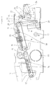
- Fig. 1 is a sketchy plan view of one embodiment according to this invention;
- Fig. 2 is a sketchy sectional view as if Fig. 1 was observed from the front;
- Fig. 3 is a front sectional view showing a usual operation condition of the embodiment of Fig. 2;
- Fig. 4 is a front sectional view showing another operation condition of the embodiment of Fig. 2;
- Fig. 5 is a side view as if Fig. 4 was observed from the right; and
- Fig. 6 is a perspective view showing a prior art example.
-
- A throw-into-type coin discriminator shown in the drawings is constructed as follows.
- The main body is a little large and is formed in the shape of a long box. On the left of said long box shape, a
hopper 11 of schematic U-shape is formed. And a plurality of coins are thrown into thehopper 11. - A first
endless belt 12 with large width is tensioned in the bottom ofhopper 11 of substantial U-shape. The thrown-into coins usually are conveyed rightward in the drawings. - In addition, although the detailed structure of
first belt 12 was omitted, it is rotated by amotor 13 which is capable of normal and reverse rotations. - Moreover, two
sensors 14 for coin or metal are arranged under the coin conveying surface of first belt 12 (see Fig. 2). - That is, if a coin is thrown into the
hopper 11, anyone of twosensors 14 will detect the coin and will output a start signal. Themotor 13 starts by this start signal, and as the result, - the
first belt 12 is actuated and the coin will be conveyed rightward in the drawings. In addition, a part of theedge 11A of the lower aperture ofhopper 11 forms a guide which is slanting to the progress direction offirst belt 12, and puts the coins in a row, as the result. - On the upper-part center of the coin discriminator, i.e., on the right-end part of
belt 12, areverse roller 15 is arranged. Thereverse roller 15 rotates such that its part confronting said first belt moves reverse to the progress direction of the upper part of said first flat belt. Thisroller 15 breaks down coins overlapped on thefirst belt 12 and puts the coins in a row and a sheet. - Near the right side upper part of coin discriminator, i.e., near the right end of the
first belt 12, a secondendless belt 16 with a large width is tensioned, and the coins are conveyed rightward in the drawings. - In addition, the
second belt 16 is rotated in normal direction by amotor 17, although the detailed structure explanation is omitted. - Still, the velocity of the
second belt 16 is faster than the velocity of thefirst belt 12. As a result, the coins which are in a row and a sheet onfirst belt 12 are separated one by one. - Under the coin conveying surface of the
second belt 16, one side of fourcoin discrimination sensors 18 are arranged in 4 pieces. - And the other side of the
discrimination sensors 18 are arranged in 4 pieces in acover 19 of the second belt 16 (see Figs. 1 and 2). - These four
discrimination sensors 18 are provided for distinguishing the diameter, thickness, and at least two kinds of materials such as for instance two metals of a coin. - A
diagonal reference line 20 is formed above the upper surface of thesecond belt 16. Thereference line 20 guides the coin which is moved and said coin is approached to the fourdiscrimination sensors 18. - The
reference line 20 is provided, for example, by a staggered groove (not shown) formed on the interior ofcover 19. - Near the right end of the
second belt 16, a long andslender selection roller 21 is arranged. Thisselection roller 21 is operated dependent on a detection whether the coin is genuine or not. It is operated by asolenoid 24 by means of a pivotedarm 22 and a pivotedlink 23. Therefore, theselection roller 21 need not to be a roller, and may be in another form which can guide an authentic coin. - At the right-hand side of
selection roller 21, a littlethick sending roller 25 is arranged. Thissending roller 25 sends out the coin further to the right-hand side when the coin is genuine. - In addition, when the coin is counterfeit, it becomes a stop body. Under the
selection roller 21, a rejection board 26 (see Fig. 5) for counterfeit coins is diagonally arranged. - The
rejection board 26 is usually projected as shown in the drawings, and is drawn into the apparatus by a solenoid (not shown), at the time of necessity. - In addition, at the upper and lower positions near the
sending roller 25, two sets ofsensors 27 for detecting the passage of an authentic coin are arranged. - Moreover, two sets of
sensors 29 for detecting the passage of a counterfeit coin are arranged at the right and left positions under the sendingroller 25. Thesensors - This embodiment which consists of an above-mentioned constituents is operated as follows. Firstly, a multiple variety of coins are fed into the
hopper 11 of trumpet type. When the coins are fed into thehopper 11, the movement offirst belt 12 is started, and the coins will be conveyed in a row by theopen edge 11A. - And the several kinds of coins conveyed in a row are levelled by the
roller 15 which is rotated such that its part confronting thebelt 12 moves reverse to the progress direction of the upper part offirst belt 12. The several kinds of coins levelled in a row are conveyed by said secondendless belt 16. - Since this
second belt 16 is quicker than the velocity of thefirst belt 12, the several kinds of coins levelled in a row will be separated from each other in the row one by one, and will be further conveyed. The multiple variety of coins conveyed apart from each other in the row one by one are guided by thediagonal reference line 20 and pass through the fourdiscrimination sensors 18. Thus, the multiple variety of coins fed into thehopper 11 pass through the fourdiscrimination sensors 18 one by one. And the authenticity and money type of each coin is judged one by one. When the coin which passed thediscrimination sensors 18 is genuine, as shown in Fig. 3, thesolenoid 24 is operated and theselection roller 21 is shifted a little to the right-hand side in the drawings, i.e. into the passage to therejection board 26. - In this way, the coin C conveyed by the
second belt 16 will be raised or kept up by theselection roller 21. The coin C raised with theselection roller 21 is further sent rightward in the drawings, by means of the sendingroller 25. When the coin which passed thediscrimination sensors 18 is a dummy, as shown in Fig. 4, thesolenoid 24 is not operated and theselection roller 21 does not move. Therefore, the counterfeit coin C conveyed with thebelt 16 will drop without reaching the sendingroller 25. - The counterfeit coin C which is dropped is guided and collides at the slanting
rejection board 26 in the standing up state, and will be sent out to the right-hand side, as shown in Fig. 5. In addition, even if the coin which passed thediscrimination sensors 18 is genuine, but the coin is not to be sent out rightward as shown in Fig. 3, for example, the coin may be guided into a spare cash box, etc.. In this case, thesolenoid 24 is not operated as shown in Fig. 4, and further a solenoid (not shown) of therejection board 26 is operated and therejection board 26 is withdrawn. - Thus, the authentic coin C conveyed with the
belt 16 will drop without reaching the sendingroller 25. - The authentic coin C which was dropped is guided in standing-up condition will pass the normal position of the
rejection board 26 which was withdrawn. As shown at the broken line of Fig. 5, the coin collides with aninclined surface 28 below the normal position of the rejection board and will be sent out to the left-hand side. - This invention as mentioned-above can align several kinds of inserted coins, and further the authenticity and money type of each coin can be distinguished with much lower space requirements than in the prior art.
- Especially, this invention rejects a counterfeit coin in the process of coin discrimination, and the large effect that only an authentic coin can be received is obtained.
Claims (5)
- A coin discriminator comprising at least:means (11, 12, 15, 16) for separating a plurality of coins one by one;means (18, 20), being mounted on the separating means, for distinguishing the separated coins; andmeans (21, 24, 25) for receiving an authentic coin, which is a separated coin detected as being genuine by the means for distinguishing.
- The coin discriminator according to claim 1, which is of the throw-into-type, and wherein the separating means (11, 12, 15, 16) comprisesmeans (11, 12, 15) for arranging a plurality of thrown-into coins in a row, andmeans (16) for separating the plurality of coins arranged in a row one by one.
- The coin discriminator as described in claim 1 or 2, wherein the means for receiving an authentic coin includes a roller means (21).
- The coin discriminator as described in one of claims 1 to 3, wherein the means for distinguishing has means (20) for guiding the separated coins to the means (18) for distinguishing.
- The coin discriminator as described in one of claims 1 to 4, wherein the means for receiving an authentic coin includes a solenoid means (24).
Applications Claiming Priority (2)
| Application Number | Priority Date | Filing Date | Title |
|---|---|---|---|
| JP09052298A JP4164560B2 (en) | 1998-03-02 | 1998-03-02 | Coin sorting machine |
| JP9052298 | 1998-03-02 |
Publications (2)
| Publication Number | Publication Date |
|---|---|
| EP0940777A1 true EP0940777A1 (en) | 1999-09-08 |
| EP0940777B1 EP0940777B1 (en) | 2004-04-21 |
Family
ID=14000784
Family Applications (1)
| Application Number | Title | Priority Date | Filing Date |
|---|---|---|---|
| EP99103312A Expired - Lifetime EP0940777B1 (en) | 1998-03-02 | 1999-02-19 | Coin discriminator |
Country Status (9)
| Country | Link |
|---|---|
| US (1) | US6086472A (en) |
| EP (1) | EP0940777B1 (en) |
| JP (1) | JP4164560B2 (en) |
| KR (1) | KR100512052B1 (en) |
| CN (1) | CN1125411C (en) |
| AU (1) | AU750849B2 (en) |
| DE (1) | DE69916519T2 (en) |
| ES (1) | ES2219944T3 (en) |
| TW (1) | TW416043B (en) |
Cited By (5)
| Publication number | Priority date | Publication date | Assignee | Title |
|---|---|---|---|---|
| WO2004057545A1 (en) * | 2002-12-22 | 2004-07-08 | Countr Gmbh | Separator |
| EP1471469A1 (en) * | 2003-04-15 | 2004-10-27 | Scheidt & Bachmann Gmbh | Apparatus for accepting coins |
| EP2034455A3 (en) * | 2007-09-07 | 2010-09-01 | adp Gauselmann GmbH | Device for feeding coins into the aperture in a coin-operated apparatus |
| EP2846313A1 (en) * | 2013-09-05 | 2015-03-11 | Wincor Nixdorf International GmbH | Coin separation system |
| EP3293710A1 (en) * | 2016-09-13 | 2018-03-14 | NGZ Geldzählmaschinengesellschaft mbH & Co. KG | Coin sorter with bypass path |
Families Citing this family (8)
| Publication number | Priority date | Publication date | Assignee | Title |
|---|---|---|---|---|
| US6896114B1 (en) * | 1999-09-03 | 2005-05-24 | Fuji Electric Co., Ltd. | Coin dispensing apparatus for automatic vending machine |
| US6695689B2 (en) * | 2000-12-13 | 2004-02-24 | Asahi Seiko Co., Ltd. | Detector unit for coin blockage in a coin dispenser |
| JP4604155B2 (en) * | 2003-04-24 | 2010-12-22 | 旭精工株式会社 | Coin separator |
| JP4899084B2 (en) * | 2005-12-27 | 2012-03-21 | 旭精工株式会社 | Coin receiving device for coin processing device |
| JP6352124B2 (en) * | 2014-09-16 | 2018-07-04 | 株式会社日本コンラックス | Coin processing equipment |
| JP6277350B2 (en) | 2014-12-16 | 2018-02-14 | 旭精工株式会社 | Coin identification device |
| JP6901658B2 (en) * | 2017-03-06 | 2021-07-14 | 旭精工株式会社 | Coin processing device and coin deposit / withdrawal device equipped with it |
| WO2019197460A1 (en) * | 2018-04-10 | 2019-10-17 | Georg Schons | Sorting device for sorting out coins |
Citations (4)
| Publication number | Priority date | Publication date | Assignee | Title |
|---|---|---|---|---|
| US4558711A (en) * | 1983-07-08 | 1985-12-17 | Glory Kogyo Kabushiki Kaisha | Coin processing apparatus |
| EP0481699A2 (en) * | 1990-10-15 | 1992-04-22 | Kabushiki Kaisha Universal | Coin supply device for coin-operated gaming machine |
| US5207611A (en) * | 1990-07-16 | 1993-05-04 | Laurel Bank Machines Co., Ltd. | Coin sorting apparatus |
| JPH09237372A (en) * | 1995-12-30 | 1997-09-09 | Asahi Seiko Kk | Coin aligner |
Family Cites Families (1)
| Publication number | Priority date | Publication date | Assignee | Title |
|---|---|---|---|---|
| JP3368313B2 (en) * | 1996-05-30 | 2003-01-20 | 旭精工株式会社 | Coin discrimination unit |
-
1998
- 1998-03-02 JP JP09052298A patent/JP4164560B2/en not_active Expired - Lifetime
-
1999
- 1999-01-26 TW TW088101271A patent/TW416043B/en not_active IP Right Cessation
- 1999-02-05 KR KR10-1999-0003850A patent/KR100512052B1/en not_active Expired - Fee Related
- 1999-02-16 AU AU17334/99A patent/AU750849B2/en not_active Ceased
- 1999-02-19 DE DE69916519T patent/DE69916519T2/en not_active Expired - Lifetime
- 1999-02-19 ES ES99103312T patent/ES2219944T3/en not_active Expired - Lifetime
- 1999-02-19 EP EP99103312A patent/EP0940777B1/en not_active Expired - Lifetime
- 1999-03-01 CN CN99102704A patent/CN1125411C/en not_active Expired - Fee Related
- 1999-03-03 US US09/262,160 patent/US6086472A/en not_active Expired - Fee Related
Patent Citations (4)
| Publication number | Priority date | Publication date | Assignee | Title |
|---|---|---|---|---|
| US4558711A (en) * | 1983-07-08 | 1985-12-17 | Glory Kogyo Kabushiki Kaisha | Coin processing apparatus |
| US5207611A (en) * | 1990-07-16 | 1993-05-04 | Laurel Bank Machines Co., Ltd. | Coin sorting apparatus |
| EP0481699A2 (en) * | 1990-10-15 | 1992-04-22 | Kabushiki Kaisha Universal | Coin supply device for coin-operated gaming machine |
| JPH09237372A (en) * | 1995-12-30 | 1997-09-09 | Asahi Seiko Kk | Coin aligner |
Non-Patent Citations (1)
| Title |
|---|
| PATENT ABSTRACTS OF JAPAN vol. 098, no. 001 30 January 1998 (1998-01-30) * |
Cited By (7)
| Publication number | Priority date | Publication date | Assignee | Title |
|---|---|---|---|---|
| WO2004057545A1 (en) * | 2002-12-22 | 2004-07-08 | Countr Gmbh | Separator |
| EP1471469A1 (en) * | 2003-04-15 | 2004-10-27 | Scheidt & Bachmann Gmbh | Apparatus for accepting coins |
| EP2034455A3 (en) * | 2007-09-07 | 2010-09-01 | adp Gauselmann GmbH | Device for feeding coins into the aperture in a coin-operated apparatus |
| EP2846313A1 (en) * | 2013-09-05 | 2015-03-11 | Wincor Nixdorf International GmbH | Coin separation system |
| WO2015032626A1 (en) * | 2013-09-05 | 2015-03-12 | Wincor Nixdorf International Gmbh | Coin separating device |
| US9672680B2 (en) | 2013-09-05 | 2017-06-06 | Wincor Nixdorf International Gmbh | Coin separating device |
| EP3293710A1 (en) * | 2016-09-13 | 2018-03-14 | NGZ Geldzählmaschinengesellschaft mbH & Co. KG | Coin sorter with bypass path |
Also Published As
| Publication number | Publication date |
|---|---|
| CN1125411C (en) | 2003-10-22 |
| TW416043B (en) | 2000-12-21 |
| AU750849B2 (en) | 2002-08-01 |
| KR19990077404A (en) | 1999-10-25 |
| AU1733499A (en) | 1999-09-16 |
| DE69916519T2 (en) | 2005-04-07 |
| US6086472A (en) | 2000-07-11 |
| JPH11250302A (en) | 1999-09-17 |
| KR100512052B1 (en) | 2005-08-31 |
| JP4164560B2 (en) | 2008-10-15 |
| CN1227943A (en) | 1999-09-08 |
| ES2219944T3 (en) | 2004-12-01 |
| DE69916519D1 (en) | 2004-05-27 |
| EP0940777B1 (en) | 2004-04-21 |
Similar Documents
| Publication | Publication Date | Title |
|---|---|---|
| US6516998B2 (en) | Self-service terminal | |
| EP0940777B1 (en) | Coin discriminator | |
| JPH11250302A5 (en) | Coin sorting machine | |
| JP3813474B2 (en) | Coin deposit and withdrawal machine | |
| JP4425603B2 (en) | Coin deposit / withdrawal device | |
| JP3973861B2 (en) | Coin deposit and withdrawal machine | |
| WO2008072545A1 (en) | Coin handling device | |
| JP4137538B2 (en) | Coin handling machine | |
| JP4017845B2 (en) | Coin deposit and withdrawal machine | |
| JP3862974B2 (en) | Coin deposit and withdrawal machine | |
| JPH10241009A (en) | Coin processing equipment | |
| JP4786966B2 (en) | Coin processing equipment | |
| WO2018101173A1 (en) | Coin delivery device | |
| JPH0330941Y2 (en) | ||
| JP2548878Y2 (en) | Circulating coin depositing and dispensing machine | |
| JP4244505B2 (en) | Coin processing equipment | |
| JPH0110700Y2 (en) | ||
| JPH0496893A (en) | Coin sorter | |
| JPH021647Y2 (en) | ||
| JPH04111091A (en) | Coin sorter | |
| JP2539489B2 (en) | Automatic cash handling device | |
| JPH0636110A (en) | Coin processor | |
| JPH0741672U (en) | Coin handling equipment | |
| JPH08273027A (en) | Paper money processor for automatic vending machine or the like | |
| JPS63206887A (en) | Paper money teller machine |
Legal Events
| Date | Code | Title | Description |
|---|---|---|---|
| PUAI | Public reference made under article 153(3) epc to a published international application that has entered the european phase |
Free format text: ORIGINAL CODE: 0009012 |
|
| AK | Designated contracting states |
Kind code of ref document: A1 Designated state(s): DE ES GB IT NL |
|
| AX | Request for extension of the european patent |
Free format text: AL;LT;LV;MK;RO;SI |
|
| 17P | Request for examination filed |
Effective date: 19990830 |
|
| AKX | Designation fees paid |
Free format text: DE ES GB IT NL |
|
| 17Q | First examination report despatched |
Effective date: 20030213 |
|
| GRAP | Despatch of communication of intention to grant a patent |
Free format text: ORIGINAL CODE: EPIDOSNIGR1 |
|
| GRAS | Grant fee paid |
Free format text: ORIGINAL CODE: EPIDOSNIGR3 |
|
| GRAA | (expected) grant |
Free format text: ORIGINAL CODE: 0009210 |
|
| AK | Designated contracting states |
Kind code of ref document: B1 Designated state(s): DE ES GB IT NL |
|
| REG | Reference to a national code |
Ref country code: GB Ref legal event code: FG4D |
|
| REF | Corresponds to: |
Ref document number: 69916519 Country of ref document: DE Date of ref document: 20040527 Kind code of ref document: P |
|
| REG | Reference to a national code |
Ref country code: ES Ref legal event code: FG2A Ref document number: 2219944 Country of ref document: ES Kind code of ref document: T3 |
|
| PLBE | No opposition filed within time limit |
Free format text: ORIGINAL CODE: 0009261 |
|
| STAA | Information on the status of an ep patent application or granted ep patent |
Free format text: STATUS: NO OPPOSITION FILED WITHIN TIME LIMIT |
|
| 26N | No opposition filed |
Effective date: 20050124 |
|
| PGFP | Annual fee paid to national office [announced via postgrant information from national office to epo] |
Ref country code: DE Payment date: 20110218 Year of fee payment: 13 Ref country code: IT Payment date: 20110221 Year of fee payment: 13 Ref country code: NL Payment date: 20110216 Year of fee payment: 13 |
|
| PGFP | Annual fee paid to national office [announced via postgrant information from national office to epo] |
Ref country code: ES Payment date: 20110228 Year of fee payment: 13 Ref country code: GB Payment date: 20110217 Year of fee payment: 13 |
|
| REG | Reference to a national code |
Ref country code: NL Ref legal event code: V1 Effective date: 20120901 |
|
| GBPC | Gb: european patent ceased through non-payment of renewal fee |
Effective date: 20120219 |
|
| PG25 | Lapsed in a contracting state [announced via postgrant information from national office to epo] |
Ref country code: IT Free format text: LAPSE BECAUSE OF NON-PAYMENT OF DUE FEES Effective date: 20120219 |
|
| REG | Reference to a national code |
Ref country code: DE Ref legal event code: R119 Ref document number: 69916519 Country of ref document: DE Effective date: 20120901 |
|
| PG25 | Lapsed in a contracting state [announced via postgrant information from national office to epo] |
Ref country code: GB Free format text: LAPSE BECAUSE OF NON-PAYMENT OF DUE FEES Effective date: 20120219 Ref country code: NL Free format text: LAPSE BECAUSE OF NON-PAYMENT OF DUE FEES Effective date: 20120901 |
|
| PG25 | Lapsed in a contracting state [announced via postgrant information from national office to epo] |
Ref country code: DE Free format text: LAPSE BECAUSE OF NON-PAYMENT OF DUE FEES Effective date: 20120901 |
|
| REG | Reference to a national code |
Ref country code: ES Ref legal event code: FD2A Effective date: 20130708 |
|
| PG25 | Lapsed in a contracting state [announced via postgrant information from national office to epo] |
Ref country code: ES Free format text: LAPSE BECAUSE OF NON-PAYMENT OF DUE FEES Effective date: 20120220 |