EP0940805A2 - Identification de bande servo dans des systèmes de bande linéaire à formats servos basés sur la temporisation - Google Patents
Identification de bande servo dans des systèmes de bande linéaire à formats servos basés sur la temporisation Download PDFInfo
- Publication number
- EP0940805A2 EP0940805A2 EP99301567A EP99301567A EP0940805A2 EP 0940805 A2 EP0940805 A2 EP 0940805A2 EP 99301567 A EP99301567 A EP 99301567A EP 99301567 A EP99301567 A EP 99301567A EP 0940805 A2 EP0940805 A2 EP 0940805A2
- Authority
- EP
- European Patent Office
- Prior art keywords
- servo bands
- servo
- data storage
- tape
- bands
- Prior art date
- Legal status (The legal status is an assumption and is not a legal conclusion. Google has not performed a legal analysis and makes no representation as to the accuracy of the status listed.)
- Granted
Links
- 238000000034 method Methods 0.000 claims abstract description 18
- 230000007704 transition Effects 0.000 claims description 35
- 238000013500 data storage Methods 0.000 claims description 29
- 230000004069 differentiation Effects 0.000 abstract description 2
- 238000010586 diagram Methods 0.000 description 1
- 230000008569 process Effects 0.000 description 1
- 230000004044 response Effects 0.000 description 1
- 230000032258 transport Effects 0.000 description 1
Images





Classifications
-
- G—PHYSICS
- G11—INFORMATION STORAGE
- G11B—INFORMATION STORAGE BASED ON RELATIVE MOVEMENT BETWEEN RECORD CARRIER AND TRANSDUCER
- G11B5/00—Recording by magnetisation or demagnetisation of a record carrier; Reproducing by magnetic means; Record carriers therefor
- G11B5/48—Disposition or mounting of heads or head supports relative to record carriers ; arrangements of heads, e.g. for scanning the record carrier to increase the relative speed
- G11B5/58—Disposition or mounting of heads or head supports relative to record carriers ; arrangements of heads, e.g. for scanning the record carrier to increase the relative speed with provision for moving the head for the purpose of maintaining alignment of the head relative to the record carrier during transducing operation, e.g. to compensate for surface irregularities of the latter or for track following
- G11B5/584—Disposition or mounting of heads or head supports relative to record carriers ; arrangements of heads, e.g. for scanning the record carrier to increase the relative speed with provision for moving the head for the purpose of maintaining alignment of the head relative to the record carrier during transducing operation, e.g. to compensate for surface irregularities of the latter or for track following for track following on tapes
Definitions
- This invention relates to linear tape systems and to methods of formatting and identifying servo bands or bands in linear tape systems having timing based servos.
- linear tape is commonly used as a medium for storing large amounts of digital data for archival purposes.
- disk-based memory is often archived on linear data storage tape.
- Data is formatted on linear tapes in a plurality of tracks that extend longitudinally along the tape.
- a tape head is moveable laterally across the tape to read or write different tracks.
- multiple tracks can be written or read at the same time by using a tape head with multiple read/write elements.
- Fig. 1 illustrates, conceptually, the use of servo bands.
- Fig. 1 shows a segment of a linear tape 10 that extends in a longitudinal direction x, and that has a lateral dimension y.
- the tape includes a plurality of servo bands 12.
- servo bands In the simplified example of Fig. 1 there are three servo bands.
- the servo bands are written to the tape during a preparatory "formatting" process, prior to actual use of the tape for data storage.
- the servo bands are spaced laterally from each other by a specified distance.
- Data tracks 14 are located between the servo bands.
- the lateral positions of the data tracks are specified relative to the servo bands.
- a tape head When reading or writing tape 10, a tape head senses the servo bands with servo read elements and positions itself precisely relative to the servo bands. Within the tape head, data read/write elements are spaced relative to the servo read elements so that the data read/write elements will be positioned over data tracks 14 when the servo read elements are positioned accurately over the corresponding servo bands.
- a linear tape might have more than three servo bands.
- Many tape heads are configured to span two adjacent servo bands at any given time and to read or write only the data tracks between those servo bands. To read or write other data tracks, such a tape head is repositioned to span two different servo bands.
- lateral position information from a servo band.
- One common way is to divide a servo band into two half bands, which are recorded with different information (such as two distinct frequencies or bursts occurring at distinct times).
- a single servo head straddles the boundary between the half bands, and position information is obtained by comparing the amplitude or phase responses of the signals generated from the respective half bands.
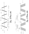
- Fig. 2 shows an example of a continuously-variable, timing-based servo pattern, along with a signal generated by a servo read element positioned over the servo pattern.
- the pattern consists of alternating magnetic transitions at two different azimuthal slopes. Relative timing of pulses generated by the read element depends on the lateral position of the head.
- the servo band illustrated in Fig. 2 has a series of magnetic transitions 20 and 22 referred to as "stripes" 20 and 22 that are recorded on the tape with alternate azimuthal slopes. Every other stripe 20 has a positive slope, while the intervening stripes 22 have negative slopes.
- Fig. 2 shows the path and width of the servo head, indicated by reference numeral 24.
- the servo head reads a lateral width that is significantly less than the full lateral width of the stripes themselves.
- the signal generated by the servo head is represented by trace 26, illustrated directly below the illustrated magnetic transition stripes.
- Lateral position information can be derived by comparing the distances between pulses. For example, a first distance A can be defined as the distance from a positive stripe to the next negative stripe, while a second distance B can be defined as the distance from a negative stripe to the next positive stripe.
- A When the servo head is centered over the servo band, A will be equal to B: consecutive pulses will occur at equal intervals.
- alternating "bursts" of stripes are used, with a burst being defined as one or more individual magnetic transition stripes.
- Fig. 3 shows an example of a servo band layout utilizing alternating bursts of magnetic transition stripes. Each burst has an opposite azimuthal slope from the previous burst.
- the servo pattern includes repeating frames. Each frame has a first subframe A and a second subframe B. Each subframe has a pair of bursts, with the bursts of each frame having different azimuthal slopes. Subframe A has a first burst 38 with five equally-spaced stripes having a positive azimuthal slope. Subframe A has a second burst 40 with five equally-spaced stripes having negative azimuthal slopes. Subframe B has similar bursts 42 and 44, except each of these bursts has four stripes.
- a patterned write head configured to simultaneously write corresponding stripes of multiple servo bands.
- Fig. 4 shows an example of patterned servo write head for writing multiple servo bands on a single linear tape.
- the head's write pattern is illustrated relative to an underlying linear tape 46 that has four servo bands 48.
- the write head pattern includes pairs of write elements or gaps.
- One element 50 of each pair is configured to produce a magnetic transition stripe having a positive slope.
- Another element 52 of each pair is configured to produce a magnetic transition stripe having a negative slope.
- a single current pulse to the head writes stripes simultaneously to all of the servo bands. Such pulses are repeated to produce stripes in the desired pattern, with the desired spacing.
- servo bands such as described above provide a high degree of relative positioning accuracy once a particular servo band has been identified, the mechanics of a tape drive generally do not provide enough absolute tape/head positioning accuracy to identify a sensed servo band and to differentiate it from other servo bands.
- the invention described herein provides a way to uniquely identify and distinguish between servo bands. This is accomplished while still maintaining the benefits of a patterned servo write head, in which a plurality of magnetic transitions are written with a single pulse to the write head.
- each timing based servo band has an identical pattern of magnetic transitions, which can be conveniently written with a patterned servo write head.
- the head is patterned so that the timing patterns of different servo bands will be offset from each other longitudinally along the linear tape. More specifically, each adjacent pair of servo bands will exhibit a different timing relationship relative to other pairs of servo bands, thereby allowing each pair to be uniquely identified and differentiated from other servo bands.
- FIG. 5 shows elements of a linear storage tape system 80 in accordance with the invention.
- System 80 includes a linear storage tape 82, a tape read/write head 84, a drive system 86 that transports the tape past the tape head, and control electronics 88.
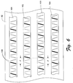
- Fig. 6 shows a segment of a linear data storage tape 82.
- a plurality of servo bands extend longitudinally along tape 82.
- the tape has four servo bands, labeled 101, 102, 103, and 104.
- a plurality of data tracks are positioned between respective pairs of servo bands. Note that Fig. 6 is drawn for purposes of conceptual illustration, and does not therefore indicate relative sizes of the various illustrated tape features.
- data storage tape 82 is designed for use with a tape head having a pair of servo read elements and a plurality of intervening data read/write elements. Accordingly, the servo bands are spaced laterally across the tape from each other, with intervening data tracks or bundles.
- read/write head 84 (Fig. 5) is positioned over an adjacent pair of servo bands while data is read or written between those servo bands using data read/write elements of the tape head.
- each set or bundle of data tracks is associated with a surrounding pair of servo bands.
- the invention allows each such pair of servo bands to be differentiated from other pairs of servo bands.
- All the servo bands have similar or identical longitudinal patterns of magnetic transitions or stripes. Each pattern is similar to the pattern shown in Fig. 4 above, comprising alternating bursts 108 of non-zero-azimuth magnetic transitions. Every other burst has transitions with positive slopes, and the intervening bursts have transitions with negative slopes.
- each burst is shown in Fig. 6 as a single line. The lines are sloped to indicate slopes of the transitions within the corresponding bursts. The bursts are arranged in pairs of positive and negative slopes.
- a frame consists of two adjacent pairs. In Fig. 6, the leading burst of a frame is indicated by a relatively wider line than the remaining bursts of a frame.
- the patterns of the respective servo bands are offset longitudinally relative to each other. More specifically, there is a different longitudinal offset between the two servo bands of each respective adjacent pair of servo bands.
- servo bands 102 and 103 are offset by half of a frame from servo bands 101 and 104. More specifically, bands 102 and 103 are positioned longitudinally so that they begin a distance d after the start of corresponding frames in bands 101 and 104 (assuming right-to-left tape movement), where d is equal to half of the length of an entire frame.
- any pair of servo bands can be uniquely identified by the timing relationship of the respective stripe frames of the two servo bands.
- the signal generated by the first servo read element (positioned over servo band 102) will coincide with the signal generated by the second read element (positioned over servo band 103).
- the signal generated by the first servo read element (positioned over servo band 103) will lag the signal generated by the second read element (positioned over servo band 104).
- a time-based comparison of any two adjacent servo band patterns differentiates any pair of servo bands from any other pair of servo bands. This allows unambiguous identification of data tracks or bundles when reading and writing data in lateral data track positions relative to the servo bands.
- Fig. 7 shows a pattern of servo read elements and data read/write elements as they are preferably configured in tape head 84.
- the pattern includes a pair of servo read elements 120 and 121, spaced laterally at the same distance as any two servo bands on tape 82.
- the servo read elements are narrow in comparison to the servo band stripes. In the described embodiment, the servo read elements are approximately 2.9% of the width of a servo band stripe. Between the servo read elements are a plurality of conventional data read/write elements 124.
- Fig. 8 shows a servo write head 84 that is used to establish servo bands on tape 82 before the tape is used for data storage.
- Servo write head 84 has a pattern of servo write elements or gaps that are activated with a single write pulse to simultaneously produce a plurality of magnetic transition stripes laterally across a linear data storage tape.
- the write element pattern is illustrated relative to linear tape 82 that includes servo bands 101, 102, 103, and 104.
- the pattern of write gaps includes at least one pair of magnetic transition stripes for each of a plurality of servo bands on the linear data storage tape. The two magnetic transition stripes of any given pair have different azimuthal slopes.
- the write head pattern includes pairs of write gaps 151, 152, 153, and 154 at different lateral positions on the write head, corresponding to servo bands 101, 102, 103, and 104.
- One gap of each pair (labeled with an "A" suffix) is configured to produce a magnetic transition stripe having a positive slope.
- Another gap of each pair (labeled with a "B" suffix) is configured to produce a magnetic transition stripe having a negative slope.
- the various write elements or gaps are pulsed repeatedly to produce the servo band pattern shown in Fig 6.
- the pairs are offset from each other in the longitudinal direction of the linear data storage tape. The offsets are calculated so that the offset between any two adjacent pairs of write elements is different from the offset between any other two adjacent pairs of write elements.
- this configuration produces identical patterns on each servo band, except that the bands written by gaps 152 and 153 trail the bands written by gaps 151 and 154 (assuming right-to-left tape movement), by a distance equal to d, which is half of a frame length.
- the invention includes a method of establishing positioning information on a linear data storage tape.
- a method of establishing positioning information on a linear data storage tape comprises writing a plurality of servo bands longitudinally along the linear data storage tape, wherein the servo bands have similar longitudinal patterns of magnetic transitions or stripes.
- the method also includes spacing the servo bands laterally across the linear data storage tape.
- the method further includes a step of longitudinally offsetting the magnetic transition patterns of the servo bands relative to each other to differentiate the servo bands from each other when subsequently reading and writing data in lateral positions relative to the servo bands.
- the invention also includes a method of determining the lateral position of a tape head relative to a linear data storage tape.
- a method includes a step of detecting patterns of magnetic transition stripes along adjacent servo bands of the linear data storage tape with the tape head.
- a further step in accordance with the invention comprises comparing time intervals between alternate transition bursts on the storage tape, to determine tape head position relative to the servo bands.
- the method further includes a step of comparing longitudinal relationships of the patterns of magnetic transition stripes to differentiate said adjacent servo bands from other servo bands on the linear data storage tape.
- the invention has been described and illustrated in the context of a system that utilizes four servo bands, the invention can also be adapted to systems using more or less servo bands.
- different offsets d are used between different adjacent pairs of servo bands, where the smallest offset is less that half of a frame length (such as 1/3 or 1/4 of a frame length), and other offsets are integer multiples of the smallest offset.
- the magnitude and direction of servo pattern timing shift are detected to determine which servo bands are currently beneath the servo read heads of the tape head.
Landscapes
- Adjustment Of The Magnetic Head Position Track Following On Tapes (AREA)
- Management Or Editing Of Information On Record Carriers (AREA)
Applications Claiming Priority (2)
| Application Number | Priority Date | Filing Date | Title |
|---|---|---|---|
| US34972 | 1987-04-06 | ||
| US09/034,972 US6169640B1 (en) | 1998-03-04 | 1998-03-04 | Servo band identification in linear tape systems having timing based servo formats |
Publications (3)
| Publication Number | Publication Date |
|---|---|
| EP0940805A2 true EP0940805A2 (fr) | 1999-09-08 |
| EP0940805A3 EP0940805A3 (fr) | 2001-07-25 |
| EP0940805B1 EP0940805B1 (fr) | 2008-06-18 |
Family
ID=21879818
Family Applications (1)
| Application Number | Title | Priority Date | Filing Date |
|---|---|---|---|
| EP99301567A Expired - Lifetime EP0940805B1 (fr) | 1998-03-04 | 1999-03-02 | Identification de bande servo dans des systèmes de bande linéaire à formats servos basés sur la temporisation |
Country Status (4)
| Country | Link |
|---|---|
| US (1) | US6169640B1 (fr) |
| EP (1) | EP0940805B1 (fr) |
| JP (1) | JP4266423B2 (fr) |
| DE (1) | DE69938908D1 (fr) |
Cited By (5)
| Publication number | Priority date | Publication date | Assignee | Title |
|---|---|---|---|---|
| EP1276099A2 (fr) | 2001-06-15 | 2003-01-15 | Fuji Photo Film Co., Ltd. | Milieu magnétique pour enregistrement et appareil associé |
| US6710967B2 (en) | 2001-12-28 | 2004-03-23 | Storage Technology Corporation | High frequency and low frequency servo pattern |
| US6744594B2 (en) | 2001-12-28 | 2004-06-01 | Storage Technology Corporation | Servo write head with gaps for writing high and low frequency transitions |
| US6937413B2 (en) | 2003-08-08 | 2005-08-30 | International Business Machines Corporation | Tape servo information with superimposed data information providing servo band identification |
| US7002763B2 (en) | 2003-08-08 | 2006-02-21 | International Business Machines Corporation | Identification of laterally positioned servo bands employing differentiating characteristics of servo patterns |
Families Citing this family (47)
| Publication number | Priority date | Publication date | Assignee | Title |
|---|---|---|---|---|
| US6269533B2 (en) * | 1999-02-23 | 2001-08-07 | Advanced Research Corporation | Method of making a patterned magnetic recording head |
| US7773340B2 (en) * | 1999-02-23 | 2010-08-10 | Advanced Research Corporation | Patterned magnetic recording head having a gap pattern with substantially elliptical or substantially diamond-shaped termination pattern |
| AU6207300A (en) * | 1999-07-09 | 2001-01-30 | Design And Test Technology, Inc. | Servo write head |
| US6496328B1 (en) | 1999-12-30 | 2002-12-17 | Advanced Research Corporation | Low inductance, ferrite sub-gap substrate structure for surface film magnetic recording heads |
| US6781778B1 (en) * | 2001-07-16 | 2004-08-24 | Imation Corp. | Time-based sectored servo data format |
| US6754022B1 (en) | 2001-07-16 | 2004-06-22 | Imation Corp. | High-speed current driver |
| US7072133B1 (en) | 2001-10-15 | 2006-07-04 | Imation Corp. | Servo mark verify head |
| US6934115B1 (en) | 2002-04-25 | 2005-08-23 | Storage Technology Corporation | Band identification using a single C-core servo write head for timing based servo patterns |
| US6912104B2 (en) * | 2002-04-30 | 2005-06-28 | Storage Technology Corporation | Timing based servo pattern incorporating band encoding |
| US7130140B1 (en) | 2002-05-06 | 2006-10-31 | Storage Technology Corporation | Polarity encoded pattern for timing based servo |
| JP2004145948A (ja) * | 2002-10-23 | 2004-05-20 | Fuji Photo Film Co Ltd | 磁気テープドライブ |
| US7139151B2 (en) * | 2003-03-03 | 2006-11-21 | Imation Corp. | Band identification in time-based servopositioning formats |
| JP4157412B2 (ja) * | 2003-04-15 | 2008-10-01 | 富士フイルム株式会社 | 磁気テープおよびその製造方法、サーボライタ、ならびにサーボバンドの識別方法および装置 |
| US6999268B2 (en) * | 2003-08-12 | 2006-02-14 | Hewlett-Packard Development Company, L.P. | Method and system of a head for a storage media |
| JP4046284B2 (ja) * | 2003-09-11 | 2008-02-13 | 富士フイルム株式会社 | 磁気テープおよびその製造方法、ならびにサーボライタおよびサーボ信号の書込み方法 |
| EP1528540A1 (fr) * | 2003-10-29 | 2005-05-04 | Storage Technology Corporation | Format d'asservissement basé sur un facteur de temps encodé en forme de bande |
| JP2005166140A (ja) * | 2003-12-01 | 2005-06-23 | Fuji Photo Film Co Ltd | 磁気テープカートリッジおよびサーボライタ、ならびに磁気テープドライブおよびサーボ信号読取方法 |
| US8144424B2 (en) * | 2003-12-19 | 2012-03-27 | Dugas Matthew P | Timing-based servo verify head and magnetic media made therewith |
| US7283317B2 (en) * | 2004-01-30 | 2007-10-16 | Advanced Research Corporation | Apparatuses and methods for pre-erasing during manufacture of magnetic tape |
| US7511907B2 (en) | 2004-02-17 | 2009-03-31 | Advanced Research Corporation | Stepped time based servo pattern and head |
| US7301716B2 (en) * | 2004-02-17 | 2007-11-27 | Advanced Research Corporation | Stepped time based servo pattern and head |
| US20100321824A1 (en) * | 2004-02-18 | 2010-12-23 | Dugas Matthew P | Magnetic recording head having secondary sub-gaps |
| US7450341B2 (en) * | 2004-05-04 | 2008-11-11 | Advanced Research Corporation | Intergrated thin film subgap subpole structure for arbitrary gap pattern magnetic recording heads and method of making the same |
| US7206170B2 (en) * | 2004-05-19 | 2007-04-17 | Imetion Corp. | Thin film servo head apparatus with canted servo gaps |
| US7280294B2 (en) * | 2004-11-30 | 2007-10-09 | International Business Machines Corporation | Tri-state servowriter driver with slow return to zero |
| US7573664B2 (en) * | 2004-12-03 | 2009-08-11 | International Business Machines Corporation | Integrated multiple channel data reliability testing for a magnetic tape drive |
| US20080068750A1 (en) * | 2006-09-19 | 2008-03-20 | International Business Machines Corporation | Planar Write Module And Hybrid Planar Write-Vertical Read Bidirectional Tape Head |
| US20080068752A1 (en) * | 2006-09-19 | 2008-03-20 | International Business Machines Corporation | Planar Bidirectional Tape Head With Planar Read And Write Elements |
| US7333291B1 (en) | 2006-09-28 | 2008-02-19 | Hewlett-Packard Development Company, L.P. | System and method for reducing tracking noise in a tape drive |
| US20080144211A1 (en) * | 2006-12-18 | 2008-06-19 | Weber Mark P | Servo techniques that mitigate an effect of read and write velocity variations on position error signal calculations |
| US7495859B2 (en) * | 2007-02-20 | 2009-02-24 | Imation Corp. | Interleaved servo pattern |
| US20090040643A1 (en) * | 2007-07-19 | 2009-02-12 | Quantum Corporation | Method and apparatus for writing timing based servo tracks on magnetic tape using complementary servo writer pairs |
| WO2009094516A1 (fr) * | 2008-01-23 | 2009-07-30 | Advanced Research Corporation | Têtes d'enregistrement comprenant des guides de bande intégrés et supports magnétiques constitués de telles têtes d'enregistrement |
| US7529061B2 (en) * | 2008-02-01 | 2009-05-05 | International Business Machines Corporation | Tape drive for maintaining lateral position utilizing longitudinally shifted servo pattern with increased sampling rate |
| US7920356B2 (en) * | 2008-02-01 | 2011-04-05 | International Business Machines Corporation | Method and system for providing a longitudinally shifted servo pattern for increased sampling rate |
| US7903368B2 (en) * | 2008-02-01 | 2011-03-08 | International Business Machines Corporation | Tape cartridge having tape media with longitudinally shifted servo pattern for increased sampling rate |
| US8068302B2 (en) * | 2008-03-28 | 2011-11-29 | Advanced Research Corporation | Method of formatting magnetic media using a thin film planar arbitrary gap pattern magnetic head |
| US7881008B2 (en) * | 2008-05-09 | 2011-02-01 | International Business Machines Corporation | Joint specification of servo format and servo reader parameters for tape drive systems |
| US7864487B2 (en) * | 2008-05-09 | 2011-01-04 | International Business Machines Corporation | Head design for writing servo patterns on magnetic tape |
| JP5080379B2 (ja) * | 2008-06-19 | 2012-11-21 | 日立マクセル株式会社 | 磁気テープ装置 |
| US7898763B2 (en) * | 2009-01-13 | 2011-03-01 | International Business Machines Corporation | Servo pattern architecture to uncouple position error determination from linear position information |
| WO2011014836A2 (fr) * | 2009-07-31 | 2011-02-03 | Advanced Research Corporation | Système de commande deffacement et procédés deffacement pour cartouche de données en bande |
| CN102725792B (zh) * | 2010-01-28 | 2015-04-08 | 国际商业机器公司 | 用于操作存储设备的方法和装置 |
| US10008226B1 (en) * | 2017-06-28 | 2018-06-26 | International Business Machines Corporation | Dynamic head offset selection for tape drive |
| JP7337036B2 (ja) * | 2020-09-30 | 2023-09-01 | 富士フイルム株式会社 | 磁気テープ、磁気テープカートリッジおよび磁気テープ装置 |
| JPWO2023079870A1 (fr) * | 2021-11-05 | 2023-05-11 | ||
| JPWO2024009665A1 (fr) * | 2022-07-08 | 2024-01-11 |
Family Cites Families (4)
| Publication number | Priority date | Publication date | Assignee | Title |
|---|---|---|---|---|
| US4007493A (en) * | 1975-05-06 | 1977-02-08 | Burroughs Corporation | Track positioning system for magnetic transducer head |
| US4314290A (en) * | 1977-06-16 | 1982-02-02 | Burroughs Corporation | Di-bit recording technique and associated servo indicia |
| US4472750A (en) * | 1981-07-02 | 1984-09-18 | Irwin Magnetic Systems, Inc. | Data record with pre-recorded transducer positioning signals, and system for utilizing same |
| US5523904A (en) * | 1992-06-24 | 1996-06-04 | Quantum Corporation | Linear tape write servo using embedded azimuth servo blocks |
-
1998
- 1998-03-04 US US09/034,972 patent/US6169640B1/en not_active Expired - Lifetime
-
1999
- 1999-01-06 JP JP00086199A patent/JP4266423B2/ja not_active Expired - Lifetime
- 1999-03-02 DE DE69938908T patent/DE69938908D1/de not_active Expired - Lifetime
- 1999-03-02 EP EP99301567A patent/EP0940805B1/fr not_active Expired - Lifetime
Cited By (8)
| Publication number | Priority date | Publication date | Assignee | Title |
|---|---|---|---|---|
| EP1276099A2 (fr) | 2001-06-15 | 2003-01-15 | Fuji Photo Film Co., Ltd. | Milieu magnétique pour enregistrement et appareil associé |
| EP1276099A3 (fr) * | 2001-06-15 | 2008-04-09 | FUJIFILM Corporation | Milieu magnétique pour enregistrement et appareil associé |
| US6710967B2 (en) | 2001-12-28 | 2004-03-23 | Storage Technology Corporation | High frequency and low frequency servo pattern |
| US6744594B2 (en) | 2001-12-28 | 2004-06-01 | Storage Technology Corporation | Servo write head with gaps for writing high and low frequency transitions |
| US6937413B2 (en) | 2003-08-08 | 2005-08-30 | International Business Machines Corporation | Tape servo information with superimposed data information providing servo band identification |
| US7002763B2 (en) | 2003-08-08 | 2006-02-21 | International Business Machines Corporation | Identification of laterally positioned servo bands employing differentiating characteristics of servo patterns |
| US7102846B2 (en) | 2003-08-08 | 2006-09-05 | International Business Machines Corporation | Identification of laterally positioned servo bands employing differentiating characteristics of servo patterns |
| US7102847B2 (en) | 2003-08-08 | 2006-09-05 | International Business Machines Corporation | Identification of laterally positioned servo bands employing differentiating characteristics of servo patterns |
Also Published As
| Publication number | Publication date |
|---|---|
| EP0940805A3 (fr) | 2001-07-25 |
| EP0940805B1 (fr) | 2008-06-18 |
| DE69938908D1 (de) | 2008-07-31 |
| JP4266423B2 (ja) | 2009-05-20 |
| JPH11273040A (ja) | 1999-10-08 |
| US6169640B1 (en) | 2001-01-02 |
Similar Documents
| Publication | Publication Date | Title |
|---|---|---|
| US6169640B1 (en) | Servo band identification in linear tape systems having timing based servo formats | |
| US5396376A (en) | Multi-track embedded servo recording format and method | |
| EP0940807B1 (fr) | Mesure de vitesse linéaire indépendante de la position latérale d'un système de bande linéaire | |
| EP0155817B1 (fr) | Méthode de préenregistrement d'informations de positionnement sur supports magnétiques d'enregistrement | |
| US6031673A (en) | Servo band verification in linear tape systems having timing-based servo formats | |
| EP1476865B1 (fr) | Systeme d'asservissement base sur un facteur temps comprenant des distances fixes entre les transitions | |
| US7102847B2 (en) | Identification of laterally positioned servo bands employing differentiating characteristics of servo patterns | |
| CN101933089B (zh) | 具有提高的采样速率的利用纵向位移的伺服图案保持横向位置的磁带驱动器 | |
| US6134070A (en) | Encoded servo track configurations, servo writer and systems/method regarding same | |
| US7139151B2 (en) | Band identification in time-based servopositioning formats | |
| US4492993A (en) | Magnetic recording tape and corresponding method providing indication of end-of-tape conditions | |
| US7199958B2 (en) | Servo head with varying write gap width | |
| US7495859B2 (en) | Interleaved servo pattern | |
| US20080117542A1 (en) | Method and System for Providing a Longitudinally Shifted Servo Pattern for Increased Sampling Rate | |
| EP0940812B1 (fr) | Encodage de position longitudinale absolue dans des systèmes de bande linéaire | |
| US4796125A (en) | Optimizing the positioning of a pair of magnetic heads relative to spaced tracks on magnetic tape | |
| EP1271477B1 (fr) | structure de positionneur à bande magnétique ayant des propriétés améliorées de synchronisation |
Legal Events
| Date | Code | Title | Description |
|---|---|---|---|
| PUAI | Public reference made under article 153(3) epc to a published international application that has entered the european phase |
Free format text: ORIGINAL CODE: 0009012 |
|
| AK | Designated contracting states |
Kind code of ref document: A2 Designated state(s): DE GB |
|
| AX | Request for extension of the european patent |
Free format text: AL;LT;LV;MK;RO;SI |
|
| RAP1 | Party data changed (applicant data changed or rights of an application transferred) |
Owner name: HEWLETT-PACKARD COMPANY, A DELAWARE CORPORATION |
|
| PUAL | Search report despatched |
Free format text: ORIGINAL CODE: 0009013 |
|
| AK | Designated contracting states |
Kind code of ref document: A3 Designated state(s): AT BE CH CY DE DK ES FI FR GB GR IE IT LI LU MC NL PT SE |
|
| AX | Request for extension of the european patent |
Free format text: AL;LT;LV;MK;RO;SI |
|
| 17P | Request for examination filed |
Effective date: 20010914 |
|
| AKX | Designation fees paid |
Free format text: DE GB |
|
| GRAP | Despatch of communication of intention to grant a patent |
Free format text: ORIGINAL CODE: EPIDOSNIGR1 |
|
| GRAS | Grant fee paid |
Free format text: ORIGINAL CODE: EPIDOSNIGR3 |
|
| GRAA | (expected) grant |
Free format text: ORIGINAL CODE: 0009210 |
|
| AK | Designated contracting states |
Kind code of ref document: B1 Designated state(s): DE GB |
|
| REG | Reference to a national code |
Ref country code: GB Ref legal event code: FG4D |
|
| REF | Corresponds to: |
Ref document number: 69938908 Country of ref document: DE Date of ref document: 20080731 Kind code of ref document: P |
|
| PLBE | No opposition filed within time limit |
Free format text: ORIGINAL CODE: 0009261 |
|
| STAA | Information on the status of an ep patent application or granted ep patent |
Free format text: STATUS: NO OPPOSITION FILED WITHIN TIME LIMIT |
|
| 26N | No opposition filed |
Effective date: 20090319 |
|
| REG | Reference to a national code |
Ref country code: GB Ref legal event code: 732E Free format text: REGISTERED BETWEEN 20120329 AND 20120404 |
|
| REG | Reference to a national code |
Ref country code: DE Ref legal event code: R082 Ref document number: 69938908 Country of ref document: DE Representative=s name: SCHOPPE, ZIMMERMANN, STOECKELER, ZINKLER, SCHE, DE Ref country code: DE Ref legal event code: R081 Ref document number: 69938908 Country of ref document: DE Owner name: HEWLETT PACKARD ENTERPRISE DEVELOPMENT LP, HOU, US Free format text: FORMER OWNER: HEWLETT-PACKARD DEVELOPMENT COMPANY, L.P., HOUSTON, TEX., US |
|
| REG | Reference to a national code |
Ref country code: GB Ref legal event code: 732E Free format text: REGISTERED BETWEEN 20160825 AND 20160831 |
|
| PGFP | Annual fee paid to national office [announced via postgrant information from national office to epo] |
Ref country code: DE Payment date: 20180219 Year of fee payment: 20 Ref country code: GB Payment date: 20180226 Year of fee payment: 20 |
|
| REG | Reference to a national code |
Ref country code: DE Ref legal event code: R071 Ref document number: 69938908 Country of ref document: DE |
|
| REG | Reference to a national code |
Ref country code: GB Ref legal event code: PE20 Expiry date: 20190301 |
|
| PG25 | Lapsed in a contracting state [announced via postgrant information from national office to epo] |
Ref country code: GB Free format text: LAPSE BECAUSE OF EXPIRATION OF PROTECTION Effective date: 20190301 |