EP0940816A2 - Diktiergerät - Google Patents
Diktiergerät Download PDFInfo
- Publication number
- EP0940816A2 EP0940816A2 EP99102580A EP99102580A EP0940816A2 EP 0940816 A2 EP0940816 A2 EP 0940816A2 EP 99102580 A EP99102580 A EP 99102580A EP 99102580 A EP99102580 A EP 99102580A EP 0940816 A2 EP0940816 A2 EP 0940816A2
- Authority
- EP
- European Patent Office
- Prior art keywords
- dictation machine
- signals
- dictation
- signal
- speech
- Prior art date
- Legal status (The legal status is an assumption and is not a legal conclusion. Google has not performed a legal analysis and makes no representation as to the accuracy of the status listed.)
- Granted
Links
Images
Classifications
-
- G—PHYSICS
- G11—INFORMATION STORAGE
- G11B—INFORMATION STORAGE BASED ON RELATIVE MOVEMENT BETWEEN RECORD CARRIER AND TRANSDUCER
- G11B31/00—Arrangements for the associated working of recording or reproducing apparatus with related apparatus
Definitions
- the invention relates to a dictation machine, which has a dictation machine housing has, in which a microphone, a speaker and a Recording / playback signal processing circuit are provided, the dictation machine housing with a headphone output socket is provided on which during the playback of in one Signal storage medium stored signals audio signals for Will be provided.
- Such dictation machines are already known and are used by many companies offered on the market. For example, such a dictation machine from Philips under the name “390 POCKET MEMO” and from Grundig sold under the name “Dh 2220".
- a dictation machine from Philips under the name “390 POCKET MEMO” and from Grundig sold under the name “Dh 2220”.
- Dictation machines can read voice signals recorded by the microphone Processing in a recording circuit on the magnetic tape one in the dictation machine inserted dictation machine cassette can be recorded.
- these known dictation machines can also be used on a Dictation machine tapes recorded signals after processing in one Playback circuit via the loudspeaker of the dictation machine reproduced and available at a headphone output socket be put.
- dictation machine as a source for Speech signals can be used in any other System are needed, especially in a system that is used for Implementation of spoken language into written text is provided or in a speech analysis system.
- those from the microphone of the dictation machine recorded signals not only via the other Connection socket output to the other system, but additionally recorded using a storage medium, then stand for later Control purposes the signals transmitted to the other system in the form a memory copy.
- level adjustment level specified in claim 5 ensures that a signal is always the same at the other connection socket Level is provided, which is when the signal is derived from the microphone regardless of the volume of the recorded Speech signal and when the signal is derived from the storage medium regardless of that by means of the volume control of the dictation machine volume is set.
- the socket occupancy detector specified in claim 6 always detects if a signal cable is connected to the other socket. Switching processes internal to the dictation machine can be carried out from its output signal can be triggered, for example that of the recording / reproducing signal processing circuit associated equalizer or the Level adjustment level.
- the bidirectional signal transmission specified in claim 8 allows supplied by the system connected to the further connection socket Play signals over the dictation machine speaker. This is for example in the learning phase or for text corrections after the Conversion of speech to text by a speech-to-text converter from Meaning if the user is to be shown acoustically which one Speech signal from the speech recognition program of the speech-text converter into which text signal has been converted, said Text signal on a cooperating with the speech-text converter Display device is shown. This means the user cannot Correct a recognized word or an unrecognized text passage or speak again and the speech-to-text converter get used to speaker-specific features.
- Claims 9 to 11 show how a dictation machine with the features the invention in an advantageous manner as a voice signal input element for a speech-to-text converter can be used. Further advantageous properties of the invention result from the exemplary explanation of the invention with reference to the figures.
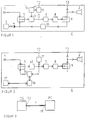
- FIG. 1 shows a block diagram of a dictation machine after a first one Embodiment for the invention, in which the signals in analog Form recorded on the magnetic tape of a dictation machine cassette become.
- the dictation machine shown has a dictation machine housing G, in which is a microphone 1, a speaker 2, and a recording / reproducing signal processing circuit are provided.
- the latter include a first record / playback switch 5 Preamplifier and equalizer 6, a level control 7, an output stage 8, a second record / playback switch 9, a circuit for Biasing and equalization 10 and a recording / reproducing head 4 on.
- the dictation machine shown has a Headphone jack 13 and an inserted dictation machine cassette 3.
- the microphone 1 recorded voice signals after a recording side Signal processing on the magnetic tape of the dictation machine cassette 3 to be recorded. Furthermore, such Dictation machine on the magnetic tape of the dictation machine cassette 3 recorded signals after a playback-side signal processing reproduced via the speaker 2 and on the headphone jack 13 for Will be provided.
- the from Microphone 1 derived signals a first input of the switch 5th fed. From there, the signals arrive via the Allow recording process for signals at the first input Switch 5 to the preamplifier and equalizer 6.
- Whose output signals are via the level control 7 and the output stage 8 to the input of second record / playback switch 9 placed, which at Recording process is in its lower switch position, so that the Output signals from the output stage 8 to the circuit 10 for biasing and equalization.
- Their output signals in turn are supplied to the recording / reproducing head 4 and onto the Transfer the magnetic tape of the dictation machine cassette 3.
- the equalizer characteristic of the equalizer 6 is advantageous switchable. For this purpose, when inserting the plug of the Connecting cable in the other connector 12 a not shown Switch contact closed, which is from the socket occupancy detector 14 is recognized. This then generates a control signal or changeover signal, due to which the equalizer characteristic of the equalizer 6 is changed. For example, if another connection socket 12 is occupied, the bandwidth the signals passing through the module 6 in comparison to the unoccupied one Condition of the connector socket 12 enlarged.
- FIG. 2 shows a block diagram of a dictation machine after a second one Embodiment for the invention, in which the signals in digital Form on a recording medium realized as a semiconductor memory 17 to be recorded.
- the dictation machine shown has a dictation machine housing G, in which is a microphone 1, a speaker 2, and a recording / reproducing signal processing circuit are provided.
- the latter include a first record / playback switch 5 Preamplifier 61, a level controller 7, an output stage 8, a second Recording / playback switch 9, a converter unit 15 with an analog-to-digital converter and a digital-to-analog converter and one Processor unit 16, which leads to data compression and expansion and for addressing the semiconductor memory 17 is provided.
- the dictation machine shown has a headphone jack 13.
- the microphone 1 recorded voice signals after a recording side Signal processing in the memory locations of the semiconductor memory 17 to be recorded. Furthermore, such Dictation device stored signals in the semiconductor memory 17 after a playback-side signal processing via the loudspeaker 2 reproduced and provided at the headphone jack 13 become.
- the from Microphone 1 derived signals a first input of the switch 5th fed. From there, the signals arrive via the Allow recording process for signals at the first input Switch 5 to the preamplifier 61. Its output signals are in Converter 15 subjected to an analog-to-digital conversion and in digital form passed on to the processor unit 16. In this one takes place Compression of the data to be recorded, which is then stored in the semiconductor memory 17 are stored, the processor unit 16 also for the associated storage management, i.e. the addressing of this memory responsible is. Since the second record / playback switch 9 itself during the recording process in its lower switch position no signals are sent to the Speaker 2 and output to the headphone jack 13.
- the output signals of the preamplifier 61 via a Level adjustment stage 11 on a further connection socket 12 of the Dictation machine provided. Since the preamplifier 61 in both Record as well as in the Wedergabesignalweg is arranged on the further connection socket 12 in the recording mode from Microphone 1 derived signals and in playback mode from the Semiconductor memory 17 reproduced signals provided. This Signals can be connected to the additional connection socket 12 connected cable to another system, for example a speech analyzer or a speech-to-text converter, as explained below in connection with Figure 3.
- FIG. 3 shows a sketch to illustrate the use of a Dictation machine according to the invention in connection with a speech-to-text converter.
- the further connection socket 12 of the dictation machine G is via a signal cable K connected to a microphone jack 18 of a personal computer PC.
- the PC has a keyboard, a screen, a computing unit, Storage means as well as a sound card.
- the the PC via the signal cable K fed signals become an audio adaptation in the sound card used to adapt the signals supplied by the dictation machine the speech-text conversion software available in the PC is necessary.
- speech-text conversion software is already on the market available and for example under the names "DRAGON-Naturally Speaking "and" IBM-Via-Voice "known. Before the practical Commissioning such software is initially a learning phase perform to get the system used to the respective speaker is provided.
- a dictation machine can be used as a signal source for a speech-to-text converter can be used, being in a first Embodiment the dictation machine essentially serves as a microphone, which to the microphone jack of the speech-to-text converter is connected and in a second embodiment already recorded dictation machine cassette or one already (compressed) Semiconductor data provided with voice data serve as a signal source.
- bidirectional signal transmission is provided between the PC and the dictation machine.
- This bidirectional signal transmission allows, for example, words or text passages that were not recognized by the computer to be reproduced via the loudspeaker of the dictation machine in the learning phase or in text corrections for converted speech into text, so that the user can correct these unrecognized words or text passages or else can speak again.
- the cable K is connected to the loudspeaker socket of a personal computer PC.
- a signal transmission from the dictation machine to the PC and vice versa is in advantageously completely regardless of whether a storage medium in the Dictation machine is used or not. Furthermore, the user must No comparison to the handling of a conventional dictation machine carry out additional operating measures in order to at the further Provide connection socket signals.
- the operation of a Dictation machine according to the invention takes place just like the operation of a conventional voice recorder so that the user has no new ones Must learn operating steps.
Landscapes
- Engineering & Computer Science (AREA)
- Multimedia (AREA)
- Signal Processing Not Specific To The Method Of Recording And Reproducing (AREA)
- Machine Translation (AREA)
- Signal Processing For Digital Recording And Reproducing (AREA)
- Developing Agents For Electrophotography (AREA)
- Liquid Crystal (AREA)
- Photographic Developing Apparatuses (AREA)
- Fittings On The Vehicle Exterior For Carrying Loads, And Devices For Holding Or Mounting Articles (AREA)
- Recording Or Reproducing By Magnetic Means (AREA)
Abstract
Description
- FIG 1
- ein Blockschaltbild eines Diktiergerätes nach einem ersten Ausführungsbeispiel für die Erfindung;
- FIG 2
- ein Blockschaltbild eines Diktiergerätes nach einem zweiten Ausführungsbeispiel für die Erfindung; und
- FIG 3
- eine Skizze zur Veranschaulichung der Verwendung eines Diktiergerätes gemäß der Erfindung in Verbindung mit einem Sprache-Text-Umsetzer.
Hierzu ist das Kabel K mit der Lautsprecherbuchse eines Personal-Computers PC verbunden.
Claims (10)
- Diktiergerät, welches ein Diktiergerätegehäuse aufweist, in welchem ein Mikrophon, ein Lautsprecher und eine Aufzeichnungs/Wiedergabesignalverarbeitungsschaltung vorgesehen sind, wobei das Diktiergerätegehäuse mit einer Kopfhörer-Ausgangsbuchse versehen ist, an welcher während der Wiedergabe von auf einem Signalspeichermedium aufgezeichneten Signalen Ausgangssignale zur Verfügung gestellt werden,
dadurch gekennzeichnet,
daß das Diktiergerätegehäuse (G) mit einer weiteren Anschlußbuchse (12) versehen ist, an welcher in einer ersten Betriebsart vom Mikrophon (1) des Diktiergerätes abgeleitete Signale und in einer zweiten Betriebsart vom Signalspeichermedium (3, 17) abgeleitete Signale zur Verfügung gestellt werden. - Diktiergerät nach Anspruch 1,
dadurch gekennzeichnet,
daß die Aufzeichnungs-/Wiedergabesignalverarbeitungsschaltung einen Aufzeichnungs-/Wiedergabe-Umschalter (5) aufweist, an dessen erstem Eingang das vom Mikrophon (1) abgeleitete Signal und an dessen zweitem Eingang das vom Signalspeichermedium (3, 17) abgeleitete Signal anliegt und dessen Ausgang mit einer Entzerrerschaltung (6) verbunden ist. - Diktiergerät nach Anspruch 2,
dadurch gekennzeichnet,
daß das an der weiteren Anschlußbuchse (12) zur Verfügung gestellte Signal vom Ausgang der Entzerrerschaltung (6) abgeleitet ist. - Diktiergerät nach einem der vorhergehenden Ansprüche,
dadurch gekennzeichnet,
daß die der weiteren Anschlußbuchse (12) zugeführten Signale über eine Pegel-Anpasssungsstufe (11) geleitet werden. - Diktiergerät nach Anspruch 4,
dadurch gekennzeichnet,
daß der Pegel der am Ausgang der Pegel-Anpassungsstufe (11) zur Verfügung gestellten Signale gleich ist. - Diktiergerät nach einem der vorhergehenden Ansprüche,
dadurch gekennzeichnet,
daß es einen Buchsenbelegungsdetektor (14) aufweist, welcher in der zweiten Betriebsart bei an die weitere Anschlußbuchse (12) angeschlossenem Verbindungskabel ein Ausgangssignal erzeugt, das dem Entzerrer (6) zur Umschaltung der Entzerrercharakteristik zugeführt ist. - Diktiergerät nach einem der vorhergehenden Ansprüche,
dadurch gekennzeichnet,
daß das Speichermedium eine in das Diktiergerätegehäuse (G) eingelegte Diktiergeräte-Kassette (3) oder ein in das Diktiergerätegehäuse eingesetzter Halbleiterspeicher (17) ist. - Diktiergerät nach einem der vorhergehenden Ansprüche,
dadurch gekennzeichnet,
daß die weitere Anschlußbuchse (12) zu einer bidirektionalen Signalübertragung vorgesehen ist. - Verwendung eines Diktiergerätes nach einem oder mehreren der vorhergehenden Ansprüche zur Eingabe von Sprachsignalen in einen Sprache-Text-Umsetzter, wobei die weitere Anschlußbuchse des Diktiergerätes über ein Verbindungskabel mit einer Eingangsbuchse des Sprache-Text-Umsetzers verbunden ist.
- Verwendung nach Anspruch 9,
dadurch gekennzeichnet,
daß die dem Sprache-Text-Umsetzer zugeführten Signale vom Mikrophon des Diktiergerätes abgeleitet sind und daß die dem Sprache-Text-Umsetzer zugeführten Signale vom Speichermedium des Diktiergerätes abgeleitete Signale sind.
Applications Claiming Priority (2)
| Application Number | Priority Date | Filing Date | Title |
|---|---|---|---|
| DE19808470 | 1998-03-02 | ||
| DE19808470A DE19808470A1 (de) | 1998-03-02 | 1998-03-02 | Diktiergerät |
Publications (3)
| Publication Number | Publication Date |
|---|---|
| EP0940816A2 true EP0940816A2 (de) | 1999-09-08 |
| EP0940816A3 EP0940816A3 (de) | 2003-06-18 |
| EP0940816B1 EP0940816B1 (de) | 2006-06-21 |
Family
ID=7859205
Family Applications (1)
| Application Number | Title | Priority Date | Filing Date |
|---|---|---|---|
| EP99102580A Expired - Lifetime EP0940816B1 (de) | 1998-03-02 | 1999-02-11 | Diktiergerät |
Country Status (3)
| Country | Link |
|---|---|
| EP (1) | EP0940816B1 (de) |
| AT (1) | ATE331286T1 (de) |
| DE (2) | DE19808470A1 (de) |
Families Citing this family (2)
| Publication number | Priority date | Publication date | Assignee | Title |
|---|---|---|---|---|
| DE19820814B4 (de) * | 1998-05-09 | 2006-10-26 | Gbs Holding Gmbh | Diktiersystem |
| DE19926360A1 (de) * | 1999-06-10 | 1999-10-21 | Grundig Ag | Verfahren und Aufzeichnung und Wiedergabe eines Sprachsignals sowie Diktiergerät zur Umsetzung des Verfahrens |
Family Cites Families (7)
| Publication number | Priority date | Publication date | Assignee | Title |
|---|---|---|---|---|
| DE3304852A1 (de) * | 1983-02-12 | 1984-08-16 | Heidi 4500 Osnabrück Händle | Sprachaufzeichnungs- und wiedergabeeinrichtung |
| AT395490B (de) * | 1991-03-01 | 1993-01-25 | Philips Nv | Taschendiktiergeraet |
| US5398220A (en) * | 1992-04-06 | 1995-03-14 | Barker; Bruce J. | Portable dictation recording device having a mechanism for transmitting recorded dictation to a remote device |
| CA2157910A1 (en) * | 1993-03-10 | 1994-09-15 | Bruce Barker | Data entry device |
| DE4319853A1 (de) * | 1993-06-16 | 1994-12-22 | Treudler Reinhard Dipl Ing Th | Diktiergerät |
| DE19704009A1 (de) * | 1996-06-12 | 1997-12-18 | Paul Zeile Kg | Spracherkennungssystem |
| DE29723223U1 (de) * | 1997-05-23 | 1998-05-14 | Grundig AG, 90762 Fürth | Diktiergerät für ein Kraftfahrzeug |
-
1998
- 1998-03-02 DE DE19808470A patent/DE19808470A1/de not_active Ceased
-
1999
- 1999-02-11 AT AT99102580T patent/ATE331286T1/de not_active IP Right Cessation
- 1999-02-11 EP EP99102580A patent/EP0940816B1/de not_active Expired - Lifetime
- 1999-02-11 DE DE59913571T patent/DE59913571D1/de not_active Expired - Lifetime
Also Published As
| Publication number | Publication date |
|---|---|
| DE59913571D1 (de) | 2006-08-03 |
| ATE331286T1 (de) | 2006-07-15 |
| EP0940816B1 (de) | 2006-06-21 |
| DE19808470A1 (de) | 1999-09-09 |
| EP0940816A3 (de) | 2003-06-18 |
Similar Documents
| Publication | Publication Date | Title |
|---|---|---|
| DE10040214B4 (de) | Verfahren und System zur automatischen Erkennung einer Aktualisierung eines Sprachmodells in einem Spracherkennungssystem | |
| DE69829802T2 (de) | Spracherkennungsapparat zum Übertragen von Sprachdaten auf einem Datenträger in Textdaten | |
| EP0712131B1 (de) | Vorrichtung zur Sprachaufzeichnung mit anschliessender Texterstellung | |
| DE102019200954A1 (de) | Signalverarbeitungseinrichtung, System und Verfahren zur Verarbeitung von Audiosignalen | |
| DE112013000760B4 (de) | Automatisches korrigieren von Sprechfehlern in Echtzeit | |
| DE102015115374A1 (de) | Audiogeräusch-verringerungsschaltung, intelligentes endgerät, welches dieses audiogeräusch-verringerungsschaltung verwendet, sowie unterrichtsverfahren | |
| DE10054583A1 (de) | Verfahren und Vorrichtung zur Behandlung von Sprachinformationen | |
| DE69721404T2 (de) | Diktiersystem | |
| DE60300374T2 (de) | Sprachaktiviertes Musikwiedergabesystem | |
| DE10040404A1 (de) | Verfahren und Vorrichtung zur Aufzeichnung/Wiedergabe von Daten | |
| EP0372639B1 (de) | System zur Spracherkennung | |
| EP1316955A1 (de) | Zwischenspeichereinrichtung | |
| EP0940816B1 (de) | Diktiergerät | |
| DE19811879C1 (de) | Einrichtung und Verfahren zum Erkennen von Sprache | |
| DE69706927T2 (de) | Diktiergerät zum speichern von sprachsignalen | |
| EP0467157A2 (de) | Sprachgesteuertes Gerät der Unterhaltungselektronik, insbesondere Videorecorder | |
| EP1252626B1 (de) | Abspielgerät für komprimierte audiodaten | |
| DE3333958A1 (de) | Vorrichtung zur abspeicherung von sprachinformationen | |
| DE19820814B4 (de) | Diktiersystem | |
| DE19944342B4 (de) | Anlage zur Aufnahme und/oder Wiedergabe von Sprache, Ton, Musik, Daten oder dergleichen Signalen | |
| EP1059637B1 (de) | Verfahren zur Erweiterung der Bandbreite von analog gespeicherten Sprachsignalen für ein Diktiergerät | |
| EP1342240A1 (de) | Verfahren zum abspeichern von akustischen informationen und verfahren zum auswählen einer nach diesem verfahren abgespeicherten information | |
| DE19652259A1 (de) | Verfahren zur Speicherung von Nachrichten auf einer Chipkarte und Gerät zur Durchführung des Verfahrens | |
| DE10065826A1 (de) | Vorrichtung und Verfahren zur Auswahl von Tonquellen in einem Fahrzeug | |
| WO2000036575A1 (de) | Bild- und tonwiedergabegerät mit speicherkarte |
Legal Events
| Date | Code | Title | Description |
|---|---|---|---|
| PUAI | Public reference made under article 153(3) epc to a published international application that has entered the european phase |
Free format text: ORIGINAL CODE: 0009012 |
|
| AK | Designated contracting states |
Kind code of ref document: A2 Designated state(s): AT BE CH CY DE DK ES FI FR GB GR IE IT LI LU MC NL PT SE |
|
| AX | Request for extension of the european patent |
Free format text: AL;LT;LV;MK;RO;SI |
|
| RAP1 | Party data changed (applicant data changed or rights of an application transferred) |
Owner name: GRUNDIG AKTIENGESELLSCHAFT |
|
| PUAL | Search report despatched |
Free format text: ORIGINAL CODE: 0009013 |
|
| AK | Designated contracting states |
Designated state(s): AT BE CH CY DE DK ES FI FR GB GR IE IT LI LU MC NL PT SE |
|
| AX | Request for extension of the european patent |
Extension state: AL LT LV MK RO SI |
|
| 17P | Request for examination filed |
Effective date: 20030523 |
|
| 17Q | First examination report despatched |
Effective date: 20031218 |
|
| AKX | Designation fees paid |
Designated state(s): AT DE FR GB IT NL |
|
| RAP1 | Party data changed (applicant data changed or rights of an application transferred) |
Owner name: GBS HOLDING GMBH |
|
| GRAP | Despatch of communication of intention to grant a patent |
Free format text: ORIGINAL CODE: EPIDOSNIGR1 |
|
| GRAS | Grant fee paid |
Free format text: ORIGINAL CODE: EPIDOSNIGR3 |
|
| GRAA | (expected) grant |
Free format text: ORIGINAL CODE: 0009210 |
|
| AK | Designated contracting states |
Kind code of ref document: B1 Designated state(s): AT DE FR GB IT NL |
|
| PG25 | Lapsed in a contracting state [announced via postgrant information from national office to epo] |
Ref country code: IT Free format text: LAPSE BECAUSE OF FAILURE TO SUBMIT A TRANSLATION OF THE DESCRIPTION OR TO PAY THE FEE WITHIN THE PRESCRIBED TIME-LIMIT;WARNING: LAPSES OF ITALIAN PATENTS WITH EFFECTIVE DATE BEFORE 2007 MAY HAVE OCCURRED AT ANY TIME BEFORE 2007. THE CORRECT EFFECTIVE DATE MAY BE DIFFERENT FROM THE ONE RECORDED. Effective date: 20060621 |
|
| REG | Reference to a national code |
Ref country code: GB Ref legal event code: FG4D Free format text: NOT ENGLISH |
|
| REF | Corresponds to: |
Ref document number: 59913571 Country of ref document: DE Date of ref document: 20060803 Kind code of ref document: P |
|
| GBT | Gb: translation of ep patent filed (gb section 77(6)(a)/1977) |
Effective date: 20060830 |
|
| ET | Fr: translation filed | ||
| PLBE | No opposition filed within time limit |
Free format text: ORIGINAL CODE: 0009261 |
|
| STAA | Information on the status of an ep patent application or granted ep patent |
Free format text: STATUS: NO OPPOSITION FILED WITHIN TIME LIMIT |
|
| 26N | No opposition filed |
Effective date: 20070322 |
|
| PGFP | Annual fee paid to national office [announced via postgrant information from national office to epo] |
Ref country code: FR Payment date: 20100225 Year of fee payment: 12 |
|
| PGFP | Annual fee paid to national office [announced via postgrant information from national office to epo] |
Ref country code: GB Payment date: 20100217 Year of fee payment: 12 Ref country code: AT Payment date: 20100217 Year of fee payment: 12 |
|
| PGFP | Annual fee paid to national office [announced via postgrant information from national office to epo] |
Ref country code: NL Payment date: 20100217 Year of fee payment: 12 |
|
| REG | Reference to a national code |
Ref country code: NL Ref legal event code: V1 Effective date: 20110901 |
|
| GBPC | Gb: european patent ceased through non-payment of renewal fee |
Effective date: 20110211 |
|
| REG | Reference to a national code |
Ref country code: FR Ref legal event code: ST Effective date: 20111102 |
|
| PG25 | Lapsed in a contracting state [announced via postgrant information from national office to epo] |
Ref country code: AT Free format text: LAPSE BECAUSE OF NON-PAYMENT OF DUE FEES Effective date: 20110211 |
|
| PG25 | Lapsed in a contracting state [announced via postgrant information from national office to epo] |
Ref country code: NL Free format text: LAPSE BECAUSE OF NON-PAYMENT OF DUE FEES Effective date: 20110901 |
|
| PG25 | Lapsed in a contracting state [announced via postgrant information from national office to epo] |
Ref country code: FR Free format text: LAPSE BECAUSE OF NON-PAYMENT OF DUE FEES Effective date: 20110228 |
|
| PG25 | Lapsed in a contracting state [announced via postgrant information from national office to epo] |
Ref country code: GB Free format text: LAPSE BECAUSE OF NON-PAYMENT OF DUE FEES Effective date: 20110211 |
|
| PGFP | Annual fee paid to national office [announced via postgrant information from national office to epo] |
Ref country code: DE Payment date: 20140327 Year of fee payment: 16 |
|
| REG | Reference to a national code |
Ref country code: DE Ref legal event code: R119 Ref document number: 59913571 Country of ref document: DE |
|
| PG25 | Lapsed in a contracting state [announced via postgrant information from national office to epo] |
Ref country code: DE Free format text: LAPSE BECAUSE OF NON-PAYMENT OF DUE FEES Effective date: 20150901 |