EP0941004A1 - Processeur de signaux de commande et systeme de communication - Google Patents
Processeur de signaux de commande et systeme de communication Download PDFInfo
- Publication number
- EP0941004A1 EP0941004A1 EP98921772A EP98921772A EP0941004A1 EP 0941004 A1 EP0941004 A1 EP 0941004A1 EP 98921772 A EP98921772 A EP 98921772A EP 98921772 A EP98921772 A EP 98921772A EP 0941004 A1 EP0941004 A1 EP 0941004A1
- Authority
- EP
- European Patent Office
- Prior art keywords
- physical signal
- link
- signal link
- over
- switching
- Prior art date
- Legal status (The legal status is an assumption and is not a legal conclusion. Google has not performed a legal analysis and makes no representation as to the accuracy of the status listed.)
- Granted
Links
Images



Classifications
-
- H—ELECTRICITY
- H04—ELECTRIC COMMUNICATION TECHNIQUE
- H04W—WIRELESS COMMUNICATION NETWORKS
- H04W36/00—Hand-off or reselection arrangements
- H04W36/0005—Control or signalling for completing the hand-off
- H04W36/0011—Control or signalling for completing the hand-off for data sessions of end-to-end connection
- H04W36/0016—Hand-off preparation specially adapted for end-to-end data sessions
-
- H—ELECTRICITY
- H04—ELECTRIC COMMUNICATION TECHNIQUE
- H04W—WIRELESS COMMUNICATION NETWORKS
- H04W80/00—Wireless network protocols or protocol adaptations to wireless operation
- H04W80/02—Data link layer protocols
Definitions
- the present invention relates to a communication system corresponding to an OSI (Open Systems Interconnection) reference model composed of layers 1 to 7, and to a control signal processing apparatus for sending and receiving a frame containing control information through the layer 1 link (physical signal link) and the layer 2 link (logical link), and a communication system including the same control signal processing apparatus.
- OSI Open Systems Interconnection
- a network performs an authentication process on a user (caller) at the time of calling.
- authentication information is exchanged between a mobile station and a network when connecting the mobile station to the network, but the authentication information results in being fairly great in quantity in order to prevent an illegal utilization.
- it In order to shorten a connection delay, it must not take a long time to exchange the authentication information.
- it In a next-generation mobile radio communication network, therefore, it is necessary to heighten the ability (physical data transfer rate) of the layer 1 link (physical signal link) used in calling and to exchange the authentication information in a short time between a mobile station and the network.
- a communication method which allocates a temporary physical signal link to a user at the time of originating a call and then allocates newly a physical signal link lower in ability instead of the temporary physical signal link after validity of the call has been confirmed by an authentication process.
- a communication method which can not only perform such a control at the time of originating a call but also perform switching over of a physical signal link without delay in response to a requirement from signal processing performed by an upper layer process and effectively utilize a limited channel resource.
- the layer 2 link is re-established when a physical signal link is re-established, the information (frame) lost at the time of releasing the layer 2 link is not retransmitted in a new layer 2 link. Therefore, it is a possibility that an upper layer 3 signal (message) disappears and the control procedure reaches a deadlock.
- the present invention has been provided in consideration of the above-mentioned circumstances, and a first object of it is to provide a control signal processing apparatus and a communication system capable of switching over a physical signal link for sending and receiving a control signal with a little overhead operation.
- a second object of the invention is to reduce to the utmost a frame loss at the time of re-establishing a physical signal link.
- the present invention provides a control signal processing apparatus which has a control function for managing establishment and maintenance of a physical signal link and a logical link, and sends and receives frames including control signals through a physical signal link and a logical link which have been established, said control signal processing apparatus comprising;
- the physical signal link switching-over means when a physical signal link switching-over request is given, performs:
- control signals are sent and received using both of a target physical signal link and an original physical signal link until the original physical link is released after the target physical signal link has been established, it is possible to avoid to the utmost a frame loss which may be caused by the switching over of a physical signal link.
- a control signal processing apparatus further comprises:
- a control signal processing apparatus is provided considering a case in which a frame transmitted from an opposite apparatus, which is provided on a mobile station of a mobile radio communication system, is lost, and the control signal apparatus request the switching over of a physical signal link before receiving a retransmission frame corresponding to the lost frame.
- a control signal processing apparatus keeps a state where both of a frame corresponding to an original physical signal link and a frame corresponding to a target physical signal link can be received until the retransmission frame has been received.
- the invention provides a communication system comprising in a network a control signal processing apparatus which has a control function of managing establishment and maintenance of a physical signal link and a logical link, and sends and receives a frame containing a control signal through a physical link and a logical link which have been established, wherein;
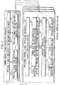
- FIG. 1 is a diagram showing the structure of a control signal processing apparatus according to an embodiment of the present invention.
- a control signal processing apparatus shown in Figure 1 is placed at a network side of a mobile radio communication system.
- a mobile station is provided with a control signal processing apparatus for exchanging control signals between itself and the control signal processing apparatus shown in Figure 1.
- the control signal processing apparatus at a mobile station side has the same composition as that shown in Figure 1 with respect to a terminating function of layer 2.
- a control signal processing apparatus is composed of a common control signal processing apparatus 1 and a plurality of individual control signal processing apparatuses 2.
- Each one of the individual control signal processing apparatuses 2 corresponds to a single layer 2 link.
- the individual control signal processing apparatuses maybe integrated into one device instead of individually providing them.
- the common control signal processing apparatus 1 and the respective individual control signal processing apparatuses 2 are actually composed of a PRU (processor unit) comprising a CPU (central processing unit), a ROM (read-only memory), a RAM (random access memory), and the like. These devices perform various functions by that a CPU executes a control program stored in the ROM or the RAM.
- a PRU processor unit
- CPU central processing unit
- ROM read-only memory
- RAM random access memory
- the common control signal processing apparatus 1 has a physical signal link-layer 2 PDU maximum length database 11 and a managing section 12.
- the physical signal link-layer 2 PDU maximum length database 11 is a database which stores information indicating correlation between a plurality of physical signal links and the maximum lengths of the PDU (protocol data unit: layer 2 frame) of the layer 2 (data link layer) which are determined based on the abilities of the physical signal links.
- the managing section 12 is means for managing a plurality of individual control signal processing apparatuses 2 with reference to this database 11.
- the managing section 12 has a physical signal link selection managing section 121 and a physical signal link switch-over managing section 122.
- the physical signal link selection managing section 121 is means for selecting a target physical signal link for a layer 2 link (hereinafter referred to as an objective layer 2 link) when switching over the physical signal link corresponding to the objective layer 2 link is requested by an outside apparatus.
- the physical signal link switch-over managing section 122 is means for supplying an indication to switch over a physical signal link to be used by an objective layer 2 link to a physical signal link selected by the physical signal link selection managing section 121 to an individual control signal processing apparatus corresponding to the objective layer 2 link.
- the individual control signal processing apparatus 2 has a plurality of layer 1 processing sections 21, a physical interface switching-over section 22, a layer 2 processing section 23, and a layer 3 processing section 24.
- Each layer 1 processing section 21 is connected with a physical interface section for providing an interface of a physical layer (layer 1), and starts or stops an operation according to an indication from the physical signal link switch-over managing section 122.
- This layer 1 processing section 21 forms a physical signal link using resources of the physical interface section during its operation.
- the physical interface switching-over section 22 connects one or plural physical signal links to the layer 2 processing section 23 according to an indication from the physical signal link switch-over managing section 122.
- the layer 2 processing section 23 is means for performing a process corresponding to a layer 2, and comprises a common section 231 and a variable section 232.
- the common section 231 is means for performing a common process regardless to a physical signal link to be used, and has a protocol processing section for processing a protocol such as LAPDM (Link Access Procedure for D channel of Mobile radio communication) and the like, and a retransmission processing section for performing a retransmission process of data which has been missed in transmission.
- a protocol processing section for processing a protocol such as LAPDM (Link Access Procedure for D channel of Mobile radio communication) and the like
- a retransmission processing section for performing a retransmission process of data which has been missed in transmission.
- variable section 232 is means for performing a process corresponding to a physical signal link which is used.
- the variable section 232 combines the layer 2 PDUs delivered from the layer 1 side and delivers the PDUs thus combined to the common section 231, and divides data delivered from the common section 231 into data units having a maximum length equal to a maximum length stored in an internal maximum length storing section (not illustrated) to create layer 2 PDUs and delivers them to the layer 1 side.
- the layer 3 processing section 24 is means for performing a process corresponding to the layer 3 (network layer).
- a first physical signal link is selected by the physical signal link selection managing section 121.
- the maximum length (called as A) of a layer 2 frame corresponding to the first physical signal link is read out from the database 11 by the physical signal link selection managing section 121 or the physical signal link switch-over managing section 122.
- the individual control signal processing apparatus 2 is notified of the information showing the first physical signal link and the information showing the maximum length A by the physical signal link switch-over managing section 122.
- a first physical signal link (layer 1 processing section 21) corresponding to the information showing the first physical signal link is then selected by the physical interface switching-over Section 22.
- the maximum length A is written in the maximum length storing section.
- the maximum length B is written in the maximum length storing section.
- a second physical signal link (layer 1 processing section 21 ) corresponding to the information showing the second physical signal link is selected, and the physical signal link is switched over from the first physical link to the second physical signal link.
- the maximum length of a layer 2 frame corresponding to the ability of a physical signal link is acquired by inquiring of the database 11, and the layer 2 frames having a maximum length equal to this maximum length is transmitted and received. Therefore, layer 2 frames having the maximum length adapted to the physical signal link can be always transmitted and received throughout before and after switching over.
- ML3 Mobile Layer 3: Mobile radio communication layer 3
- ML2 is a layer for transmitting control signals and the like for mobile radio communication, being equivalent to said layer 2.
- a control program to be stored in the ROM or RAM does not have to be one program, but one of several control programs may be performed. Accordingly, a typical operation of a control program adoptable in this embodiment is described in several cases.
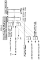
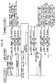
- FIG. 2 shows a switching-over operation 1 performed in this embodiment.
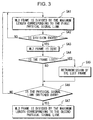
- FIG. 3 is a flowchart showing a control flow of the control signal processing apparatus for performing the switching-over operation 1.
- the maximum length corresponding to each one of all physical signal links is determined independently of those of the other physical signal links but the maximum length is determined according to the ability of the physical signal link.
- a process of taking out an ML2 frame of a length (maximum length of the first physical signal link) written in the maximum length storing section of the PDU dividing/combining section from the ML3 frame A is repeated until the all information of the ML3 has been taken out and the ML3 frame has no ML2 frame to be taken out (steps SA1 and SA2 of Figure 3).
- step SA3 all ML2 frames A-1, A-2 and A-3 thus generated are sequentially transmitted.
- step SA4 a judgement is made as to whether or not a frame loss has happened.
- step SA5 When a frame loss has happened, a retransmission process for the lost frame is performed (step SA5). After this retransmission process, a judgement is made as to whether or not the physical signal link has been switched over (step SA6).
- step SA6 In case that no frame loss has happened, immediately after the step SA4 a judgment is performed with respect to switching over of the physical signal link (step SA6).
- a layer 2 frame having a maximum length which corresponds to the first physical signal link and does not correspond to the second physical signal link is generated as a retransmission frame corresponding to the lost frame (ML2 frame A-2), and is retransmitted using the second physical signal link.
- the reason why retransmission of a layer 2 frame lost before switching over a physical signal link is performed using a layer 2 frame having the maximum length corresponding to an original physical signal link is to simplify the control for retransmission by equalizing the length of the retransmission frame to that of the lost frame and by correlating the retransmission frame to the lost frame one by one.
- the receiver keeps an operational state for receiving not only frames having the maximum length corresponding to the second physical signal link but also frames having the maximum length corresponding to the first physical signal link.
- the mobile station When a retransmission frame having the maximum length corresponding to the first physical signal link has reached the mobile station through the second physical signal link, the mobile station sends confirmation of delivery of the lost frame to the network side.
- step SA7 when the layer 2 processing section 23 of a control signal processing apparatus at the network side receives the confirmation of delivery of the lost frame, an ML3 frame delivered from the layer 3 processing section 24 is then divided by the maximum length of the second physical signal link to generate ML2 frames, and the ML2 frames are sequentially transmitted through the second physical signal link (step SA7).
- FIG 4 shows a switching-over operation 2 in this embodiment.
- this switching-over operation 2 plural ML2 frames are created by dividing one ML3 frame, and each time one of these ML2 frames is transmitted, a judgment is performed with respect to a retransmission process of a lost frame or a switching-over process to a second physical signal link.
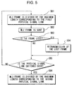
- Figure 5 is a flowchart showing a control flow for performing this switching-over operation 2. In this switching-over operation 2, it is assumed that the maximum length corresponding to each physical signal link is determined independently of those corresponding to the other physical signal links in the same way as the switching-over operation 1.
- the layer 2 processing section 23 takes out an ML2 frame A-1 having a maximum length equal to a length (maximum length of the first physical signal link) stored in the maximum length storing section of the PDU dividing/combining section from said ML3 frame A (step SB1).
- the layer 2 processing section 23 then transmits this taken-out ML2 frame through the first physical signal link (step SB2).
- step SB3 In case that confirmation of delivery of the transmitted ML2 frame A-1 has been received, it is judged that no frame loss has happened (step SB3), and a judgement is made as to whether or not a physical signal link is to be switched over (step SB5).
- the physical signal link has not switched over, the next ML2 frame A-2 is taken out and transmitted (steps SB1 and SB2).
- the ML2 frame A-2 has been lost. Therefore, a retransmission process for the lost frame is performed (step SB4).
- the first physical signal link has been switched over to the second physical signal link before this retransmission process.
- the lost frame (ML2 frame A-2) having the maximum length corresponding to the first physical signal link is transmitted. Accordingly, operation of the receiver side is the same as the example of Figure 2.
- FIG 6 shows a switching-over operation 3 in this embodiment.
- this switching-over operation 3 one ML3 frame is divided into plural ML2 frames, and each time one of the ML2 frames is transmitted, operations for retransmission of a lost frame or switching over to the second physical signal link are performed. Furthermore, in this switching-over operation 3, it is assumed that maximum frame lengths corresponding to the all physical signal links have a same length.
- Figure 7 is a flowchart showing a control flow for performing this switching-over operation 3.
- a process shown in Figure 7 includes steps SC1 to SC4 of the same process as steps SB1 to SB4, but a process of switching over the maximum length of an ML2 frame according to switching over of a physical signal link (a process corresponding to steps SB5 and SB6 in Figure 5) is cancelled.
- a switching-over operation of the whole mobile radio communication system using a control signal processing apparatus for example, a user's calling operation, a bearer switching-over operation and a plurality of calls are mentioned as an opportunity when a physical signal link is to be switched over. Outlines of them are described as follows. a. Switching-over process of a physical signal link when a user originates a call
- a connection delay In a mobile radio communication system, it is required to reduce a connection delay to a short time.
- negotiations such as authentication and the like are quickly performed by allocating an individual high-speed physical signal link (SDCCH) for sending and receiving control signals.
- SDCCH physical signal link
- TCH Traffic Channel: information channel
- the amount of control signals to be exchanged between a mobile station and the network side becomes less.
- a physical signal link for exchanging control signals is to be switched over to an ACCH (Associated Control Channel) associated with the TCH.
- ACCH Associated Control Channel
- the system When a layer 2 link once established is released at the time of switching over the physical signal link for control signals, it is necessary to newly send and receive control signals for releasing and re-establishing the layer 2 link, and therefore the radio resources are wastefully used. Thereupon, in order to effectively utilize the radio resources, taking establishment of a TCH as an opportunity, the system generates a physical signal link switching-over request and switches over a physical signal link for control signals from an SDCCH to an ACCH without releasing a layer 2 link.
- Change of a user's application namely, such change of a teleservice that a user performing a voice communication changes it to a facsimile communication as keeping the line is sometimes performed, and in such a case, change of a bearer is sometimes performed for reasons of restrictions of radio resources and the like.
- this bearer change is performed, the structure of a radio frame is changed in a radio section and a bearer rate is changed, and so a TCH is re-established.
- control signals for controlling a voice communication or a facsimile communication are sent and received through an ACCH associated with the TCH. Therefore, when a TCH is switched over with switching over from a voice communication to a facsimile communication, naturally an ACCH also results in being switched over.
- transmission is performed also in a wire section in the form of inheriting a radio frame as it is, it is necessary to change a physical signal link for control signals also in the wire section.
- a bearer change is performed.
- the system provides a bearer of 64 kbps in rate when there are such non-limited data services at 64 kbps to 128 kbps and the network is congested, and where the system integrates two bearers of 64 kbps to provide a bearer of 128 kbps when the system comes to have a margin in resources.
- the rate of radio frames change, it is necessary to switch over the ACCH.
- the system In such a case where a switching-over operation of an ACCH has happened as described above, the system generates a physical signal link switching-over request as described above and switches over the ACCH without releasing a layer 2 link.
- a service in which plural terminals are connected with one mobile station and plural calls are handled at the same time is under examination.
- an ACCH Associated Control Channel
- an ACCH associated Control Channel associated with the TCH of a first call is shared with and used by all calls.
- the first call ends although another call is continued.
- the ACCH disappears due to end of the first call, and so control signals for the remaining calls cannot be sent and received.
- the system generates a physical signal link switching-over request as described above, establishes an ACCH in the TCH of one of the remaining calls without releasing the layer 2 links corresponding to the remaining calls, and continues sending and receiving control signals for keeping the remaining calls by using this ACCH.
- a trigger for switching over a physical signal link is given by an indication from the ML3 processing section (layer 3 processing section 24).
- MS designates a mobile station
- BTS designates a base station
- MSC designates a mobile radio communication exchange station.
- a mobile radio communication exchange station MSC comprises an RNC (Radio Access Network Controller).
- the RNC includes an apparatus M-SIG (a signal-to-mobile-station processing apparatus) at the network side for terminating signals transmitted to or received from a mobile station, namely, an apparatus corresponding to an individual control signal processing apparatus according to this embodiment.
- M-SIG a signal-to-mobile-station processing apparatus
- a mobile station also comprises a control signal processing apparatus (not illustrated) for sending and receiving control signals, being opposite to this M-SIG.
- a physical signal link to be used in transmission and reception becomes only the second physical signal link.
Landscapes
- Engineering & Computer Science (AREA)
- Computer Networks & Wireless Communication (AREA)
- Signal Processing (AREA)
- Mobile Radio Communication Systems (AREA)
- Communication Control (AREA)
Applications Claiming Priority (3)
| Application Number | Priority Date | Filing Date | Title |
|---|---|---|---|
| JP14426197 | 1997-06-02 | ||
| JP14426197 | 1997-06-02 | ||
| PCT/JP1998/002260 WO1998056205A1 (fr) | 1997-06-02 | 1998-05-22 | Processeur de signaux de commande et systeme de communication |
Publications (3)
| Publication Number | Publication Date |
|---|---|
| EP0941004A1 true EP0941004A1 (fr) | 1999-09-08 |
| EP0941004A4 EP0941004A4 (fr) | 2005-01-26 |
| EP0941004B1 EP0941004B1 (fr) | 2006-10-11 |
Family
ID=15357987
Family Applications (1)
| Application Number | Title | Priority Date | Filing Date |
|---|---|---|---|
| EP98921772A Expired - Lifetime EP0941004B1 (fr) | 1997-06-02 | 1998-05-22 | Processeur de signaux de commande et systeme de communication |
Country Status (5)
| Country | Link |
|---|---|
| US (1) | US6611505B1 (fr) |
| EP (1) | EP0941004B1 (fr) |
| JP (1) | JP3868507B2 (fr) |
| DE (1) | DE69836125T2 (fr) |
| WO (1) | WO1998056205A1 (fr) |
Families Citing this family (2)
| Publication number | Priority date | Publication date | Assignee | Title |
|---|---|---|---|---|
| EP1067809B1 (fr) * | 1999-07-05 | 2013-04-10 | TELEFONAKTIEBOLAGET LM ERICSSON (publ) | Méthode pour accroître la flexibilité d'un réseau de communication avec traitement d'appel et de connexion séparés |
| CN102282827B (zh) | 2009-01-21 | 2014-06-04 | 日本电气株式会社 | 信令处理装置、链路切换方法 |
Family Cites Families (14)
| Publication number | Priority date | Publication date | Assignee | Title |
|---|---|---|---|---|
| JP2799406B2 (ja) | 1989-06-09 | 1998-09-17 | 日本電信電話株式会社 | 移動通信信号方式 |
| CA2044718C (fr) * | 1990-06-18 | 1998-07-28 | Katsumi Omuro | Systeme de reacheminement et de renvoi sur la liaison normale pour reseau a mode de transfert asynchrone |
| GB2266641B (en) * | 1992-04-24 | 1995-09-27 | Nokia Mobile Phones Ltd | Digital mobile telephone control system |
| JPH05336198A (ja) | 1992-06-02 | 1993-12-17 | Nec Corp | 通信手順制御方法および装置 |
| JP3260011B2 (ja) * | 1993-07-13 | 2002-02-25 | 松下電器産業株式会社 | 移動体通信システムの通話路管理方法および移動体通信システム |
| JP3011831B2 (ja) | 1993-07-29 | 2000-02-21 | 株式会社ケンウッド | 直流電源の逆接続保護回路 |
| US6167248A (en) * | 1993-09-06 | 2000-12-26 | Nokia Mobile Phones Ltd. | Data transmission in a radio telephone network |
| FI953264L (fi) * | 1993-11-01 | 1995-06-30 | Ericsson Telefon Ab L M | Solukkojärjestelmän tason 2 yhteyskäytäntö |
| US5530693A (en) * | 1995-06-06 | 1996-06-25 | Averbuch; Rod | Method and apparatus for performing handoff in a packet data communication system |
| US5822311A (en) * | 1996-03-05 | 1998-10-13 | Ericsson Inc. | Random access scheme for mobile satellite communications |
| US5926469A (en) * | 1996-11-12 | 1999-07-20 | Telefonaktiebolaget L/M Ericssoon (Publ) | Channel resource management within a digital mobile communications network |
| US5896376A (en) * | 1996-12-13 | 1999-04-20 | Ericsson Inc. | Optimal use of logical channels within a mobile telecommunications network |
| US5940763A (en) * | 1997-04-23 | 1999-08-17 | Ericsson, Inc. | Enhanced preemption within a mobile telecommunications network |
| US6151482A (en) * | 1997-09-30 | 2000-11-21 | Telefonaktiebolaget Lm (Publ) | Operation and maintenance link for antenna equipment |
-
1998
- 1998-05-22 EP EP98921772A patent/EP0941004B1/fr not_active Expired - Lifetime
- 1998-05-22 JP JP55024398A patent/JP3868507B2/ja not_active Expired - Lifetime
- 1998-05-22 DE DE69836125T patent/DE69836125T2/de not_active Expired - Lifetime
- 1998-05-22 WO PCT/JP1998/002260 patent/WO1998056205A1/fr not_active Ceased
- 1998-05-22 US US09/230,218 patent/US6611505B1/en not_active Expired - Fee Related
Also Published As
| Publication number | Publication date |
|---|---|
| EP0941004A4 (fr) | 2005-01-26 |
| JP3868507B2 (ja) | 2007-01-17 |
| WO1998056205A1 (fr) | 1998-12-10 |
| DE69836125T2 (de) | 2007-08-16 |
| DE69836125D1 (de) | 2006-11-23 |
| EP0941004B1 (fr) | 2006-10-11 |
| US6611505B1 (en) | 2003-08-26 |
Similar Documents
| Publication | Publication Date | Title |
|---|---|---|
| US6944452B2 (en) | Apparatus and method for hard handoff of data packet transmissions | |
| US6125276A (en) | Inter-exchange signaling for in-call service change requests | |
| RU2201035C2 (ru) | Способ, устройство и сеть связи для устранения наложения сигналов при проведении радиосвязи | |
| JP4031054B2 (ja) | システム間ソフト・ハンドオフを実施するセルラー電話システム及び方法 | |
| US8855695B2 (en) | Combined base transceiver station and base station controller data call | |
| KR100373564B1 (ko) | 패킷 전송 방법 및 시스템 | |
| KR101067135B1 (ko) | 무선 액세스 네트워크 및 이동국 사이의 무선 통신 재설정 | |
| JP2005117694A (ja) | 無線電話システム、及び無線電話ネットワーク内でのデータ送信方法、無線電話器並びに固定局 | |
| JPH08500953A (ja) | 一つのカバレージ・エリアから別のカバレージ・エリアに無線電話呼を転送する方法および装置 | |
| JP2003507946A5 (fr) | ||
| US7242943B2 (en) | Method and system for establishing a connection in a telecommunication network having different protocols | |
| KR19990007279A (ko) | 무선 원격 통신 시스템 및 소스 전송 달성 방법 | |
| US6377572B1 (en) | Virtual resource allocation method and apparatus for wireless data communication systems | |
| AU715374B2 (en) | Remote vocoding over a long distance link | |
| WO2002001903A1 (fr) | Etablissement d'appel dans un systeme de telecommunications mobile | |
| EP0941004B1 (fr) | Processeur de signaux de commande et systeme de communication | |
| US20030096619A1 (en) | Data transmission in a telecommunications network | |
| EP1044576B1 (fr) | Procede d'attribution de canaux dans un systeme mobile et systeme mobile, station de base et controleur de station de base correspondants | |
| JP2003224882A (ja) | Cdma移動通信システムおよびその記録媒体 | |
| KR100754648B1 (ko) | 이종 이동통신 시스템 사이의 핸드 오버 방법 및 그 시스템 | |
| KR101161025B1 (ko) | 이동통신 시스템에서 트래픽 채널을 미리 설정하는 방법 및장치 | |
| EP2178329B1 (fr) | Procédé d'interfaçage dans des réseaux de communications mobiles et fixes et système de communication | |
| EP2208388B1 (fr) | Procédé et système de commande d'admission de réseau ip | |
| KR100605865B1 (ko) | 이동통신 시스템에서 호 설정 방법 및 장치 | |
| JP4385025B2 (ja) | Dtm通信装置及び方法 |
Legal Events
| Date | Code | Title | Description |
|---|---|---|---|
| PUAI | Public reference made under article 153(3) epc to a published international application that has entered the european phase |
Free format text: ORIGINAL CODE: 0009012 |
|
| 17P | Request for examination filed |
Effective date: 19990128 |
|
| AK | Designated contracting states |
Kind code of ref document: A1 Designated state(s): DE GB SE |
|
| A4 | Supplementary search report drawn up and despatched |
Effective date: 20041210 |
|
| 17Q | First examination report despatched |
Effective date: 20050513 |
|
| RIN1 | Information on inventor provided before grant (corrected) |
Inventor name: NAKANO, MASATOMO Inventor name: MORIKAWA, HIROKI Inventor name: NAKAMURA, SHIN,701, MAX TOWER |
|
| RIN1 | Information on inventor provided before grant (corrected) |
Inventor name: NAKANO, MASATOMO Inventor name: MORIKAWA, HIROKI Inventor name: NAKAMURA, SHIN,701, MAX TOWER |
|
| GRAP | Despatch of communication of intention to grant a patent |
Free format text: ORIGINAL CODE: EPIDOSNIGR1 |
|
| GRAS | Grant fee paid |
Free format text: ORIGINAL CODE: EPIDOSNIGR3 |
|
| GRAA | (expected) grant |
Free format text: ORIGINAL CODE: 0009210 |
|
| RIN1 | Information on inventor provided before grant (corrected) |
Inventor name: NAKANO, MASATOMO, C/O NTT DOCOMO, INC - IPD Inventor name: MORIKAWA, HIROKI, C/O NTT DOCOMO, INC. - IPD Inventor name: NAKAMURA, SHIN, C/O NTT DOCOMO, INC. - IPD |
|
| AK | Designated contracting states |
Kind code of ref document: B1 Designated state(s): DE GB SE |
|
| REG | Reference to a national code |
Ref country code: GB Ref legal event code: FG4D |
|
| REF | Corresponds to: |
Ref document number: 69836125 Country of ref document: DE Date of ref document: 20061123 Kind code of ref document: P |
|
| REG | Reference to a national code |
Ref country code: SE Ref legal event code: TRGR |
|
| PLBE | No opposition filed within time limit |
Free format text: ORIGINAL CODE: 0009261 |
|
| STAA | Information on the status of an ep patent application or granted ep patent |
Free format text: STATUS: NO OPPOSITION FILED WITHIN TIME LIMIT |
|
| 26N | No opposition filed |
Effective date: 20070712 |
|
| PGFP | Annual fee paid to national office [announced via postgrant information from national office to epo] |
Ref country code: SE Payment date: 20110512 Year of fee payment: 14 |
|
| PGFP | Annual fee paid to national office [announced via postgrant information from national office to epo] |
Ref country code: GB Payment date: 20110518 Year of fee payment: 14 |
|
| PGFP | Annual fee paid to national office [announced via postgrant information from national office to epo] |
Ref country code: DE Payment date: 20110518 Year of fee payment: 14 |
|
| REG | Reference to a national code |
Ref country code: SE Ref legal event code: EUG |
|
| GBPC | Gb: european patent ceased through non-payment of renewal fee |
Effective date: 20120522 |
|
| PG25 | Lapsed in a contracting state [announced via postgrant information from national office to epo] |
Ref country code: SE Free format text: LAPSE BECAUSE OF NON-PAYMENT OF DUE FEES Effective date: 20120523 |
|
| REG | Reference to a national code |
Ref country code: DE Ref legal event code: R119 Ref document number: 69836125 Country of ref document: DE Effective date: 20121201 |
|
| PG25 | Lapsed in a contracting state [announced via postgrant information from national office to epo] |
Ref country code: GB Free format text: LAPSE BECAUSE OF NON-PAYMENT OF DUE FEES Effective date: 20120522 |
|
| PG25 | Lapsed in a contracting state [announced via postgrant information from national office to epo] |
Ref country code: DE Free format text: LAPSE BECAUSE OF NON-PAYMENT OF DUE FEES Effective date: 20121201 |