EP0941413B1 - Spielfreie verbindung für ein drehendes anschlussteil einer betätigungszuganordnung - Google Patents
Spielfreie verbindung für ein drehendes anschlussteil einer betätigungszuganordnung Download PDFInfo
- Publication number
- EP0941413B1 EP0941413B1 EP97948491A EP97948491A EP0941413B1 EP 0941413 B1 EP0941413 B1 EP 0941413B1 EP 97948491 A EP97948491 A EP 97948491A EP 97948491 A EP97948491 A EP 97948491A EP 0941413 B1 EP0941413 B1 EP 0941413B1
- Authority
- EP
- European Patent Office
- Prior art keywords
- conduit
- fitting
- molded sleeve
- partial spherical
- end fitting
- Prior art date
- Legal status (The legal status is an assumption and is not a legal conclusion. Google has not performed a legal analysis and makes no representation as to the accuracy of the status listed.)
- Expired - Lifetime
Links
- 230000033001 locomotion Effects 0.000 claims abstract description 34
- 230000013011 mating Effects 0.000 claims description 5
- 239000000314 lubricant Substances 0.000 claims description 3
- 238000000465 moulding Methods 0.000 description 7
- 230000000712 assembly Effects 0.000 description 6
- 238000000429 assembly Methods 0.000 description 6
- 239000000463 material Substances 0.000 description 6
- 238000000034 method Methods 0.000 description 6
- 230000005540 biological transmission Effects 0.000 description 3
- 239000011248 coating agent Substances 0.000 description 2
- 238000000576 coating method Methods 0.000 description 2
- 238000004519 manufacturing process Methods 0.000 description 2
- 238000004026 adhesive bonding Methods 0.000 description 1
- 230000001627 detrimental effect Effects 0.000 description 1
- 239000000945 filler Substances 0.000 description 1
- 239000000446 fuel Substances 0.000 description 1
- 238000002955 isolation Methods 0.000 description 1
- 239000002184 metal Substances 0.000 description 1
- 238000012986 modification Methods 0.000 description 1
- 230000004048 modification Effects 0.000 description 1
- 239000004033 plastic Substances 0.000 description 1
- 230000000717 retained effect Effects 0.000 description 1
- 230000035939 shock Effects 0.000 description 1
- 238000003466 welding Methods 0.000 description 1
Images
Classifications
-
- F—MECHANICAL ENGINEERING; LIGHTING; HEATING; WEAPONS; BLASTING
- F16—ENGINEERING ELEMENTS AND UNITS; GENERAL MEASURES FOR PRODUCING AND MAINTAINING EFFECTIVE FUNCTIONING OF MACHINES OR INSTALLATIONS; THERMAL INSULATION IN GENERAL
- F16C—SHAFTS; FLEXIBLE SHAFTS; ELEMENTS OR CRANKSHAFT MECHANISMS; ROTARY BODIES OTHER THAN GEARING ELEMENTS; BEARINGS
- F16C1/00—Flexible shafts; Mechanical means for transmitting movement in a flexible sheathing
- F16C1/26—Construction of guiding-sheathings or guiding-tubes
- F16C1/262—End fittings; Attachment thereof to the sheathing or tube
- F16C1/265—End fittings; Attachment thereof to the sheathing or tube with a swivel tube connected to the end-fitting of a sheathing, e.g. with a spherical joint
-
- F—MECHANICAL ENGINEERING; LIGHTING; HEATING; WEAPONS; BLASTING
- F16—ENGINEERING ELEMENTS AND UNITS; GENERAL MEASURES FOR PRODUCING AND MAINTAINING EFFECTIVE FUNCTIONING OF MACHINES OR INSTALLATIONS; THERMAL INSULATION IN GENERAL
- F16C—SHAFTS; FLEXIBLE SHAFTS; ELEMENTS OR CRANKSHAFT MECHANISMS; ROTARY BODIES OTHER THAN GEARING ELEMENTS; BEARINGS
- F16C1/00—Flexible shafts; Mechanical means for transmitting movement in a flexible sheathing
- F16C1/10—Means for transmitting linear movement in a flexible sheathing, e.g. "Bowden-mechanisms"
- F16C1/102—Arrangements to mount end fittings of the sheathings to support walls or brackets
- F16C1/103—Arrangements to mount end fittings of the sheathings to support walls or brackets to a hole in the wall or bracket
-
- F—MECHANICAL ENGINEERING; LIGHTING; HEATING; WEAPONS; BLASTING
- F16—ENGINEERING ELEMENTS AND UNITS; GENERAL MEASURES FOR PRODUCING AND MAINTAINING EFFECTIVE FUNCTIONING OF MACHINES OR INSTALLATIONS; THERMAL INSULATION IN GENERAL
- F16C—SHAFTS; FLEXIBLE SHAFTS; ELEMENTS OR CRANKSHAFT MECHANISMS; ROTARY BODIES OTHER THAN GEARING ELEMENTS; BEARINGS
- F16C2326/00—Articles relating to transporting
- F16C2326/01—Parts of vehicles in general
-
- F—MECHANICAL ENGINEERING; LIGHTING; HEATING; WEAPONS; BLASTING
- F16—ENGINEERING ELEMENTS AND UNITS; GENERAL MEASURES FOR PRODUCING AND MAINTAINING EFFECTIVE FUNCTIONING OF MACHINES OR INSTALLATIONS; THERMAL INSULATION IN GENERAL
- F16C—SHAFTS; FLEXIBLE SHAFTS; ELEMENTS OR CRANKSHAFT MECHANISMS; ROTARY BODIES OTHER THAN GEARING ELEMENTS; BEARINGS
- F16C2360/00—Engines or pumps
- F16C2360/22—Internal combustion engines
-
- F—MECHANICAL ENGINEERING; LIGHTING; HEATING; WEAPONS; BLASTING
- F16—ENGINEERING ELEMENTS AND UNITS; GENERAL MEASURES FOR PRODUCING AND MAINTAINING EFFECTIVE FUNCTIONING OF MACHINES OR INSTALLATIONS; THERMAL INSULATION IN GENERAL
- F16C—SHAFTS; FLEXIBLE SHAFTS; ELEMENTS OR CRANKSHAFT MECHANISMS; ROTARY BODIES OTHER THAN GEARING ELEMENTS; BEARINGS
- F16C2361/00—Apparatus or articles in engineering in general
- F16C2361/65—Gear shifting, change speed gear, gear box
-
- Y—GENERAL TAGGING OF NEW TECHNOLOGICAL DEVELOPMENTS; GENERAL TAGGING OF CROSS-SECTIONAL TECHNOLOGIES SPANNING OVER SEVERAL SECTIONS OF THE IPC; TECHNICAL SUBJECTS COVERED BY FORMER USPC CROSS-REFERENCE ART COLLECTIONS [XRACs] AND DIGESTS
- Y10—TECHNICAL SUBJECTS COVERED BY FORMER USPC
- Y10T—TECHNICAL SUBJECTS COVERED BY FORMER US CLASSIFICATION
- Y10T74/00—Machine element or mechanism
- Y10T74/20—Control lever and linkage systems
- Y10T74/20396—Hand operated
- Y10T74/20402—Flexible transmitter [e.g., Bowden cable]
-
- Y—GENERAL TAGGING OF NEW TECHNOLOGICAL DEVELOPMENTS; GENERAL TAGGING OF CROSS-SECTIONAL TECHNOLOGIES SPANNING OVER SEVERAL SECTIONS OF THE IPC; TECHNICAL SUBJECTS COVERED BY FORMER USPC CROSS-REFERENCE ART COLLECTIONS [XRACs] AND DIGESTS
- Y10—TECHNICAL SUBJECTS COVERED BY FORMER USPC
- Y10T—TECHNICAL SUBJECTS COVERED BY FORMER US CLASSIFICATION
- Y10T74/00—Machine element or mechanism
- Y10T74/20—Control lever and linkage systems
- Y10T74/20396—Hand operated
- Y10T74/20402—Flexible transmitter [e.g., Bowden cable]
- Y10T74/20408—Constant tension sustaining
-
- Y—GENERAL TAGGING OF NEW TECHNOLOGICAL DEVELOPMENTS; GENERAL TAGGING OF CROSS-SECTIONAL TECHNOLOGIES SPANNING OVER SEVERAL SECTIONS OF THE IPC; TECHNICAL SUBJECTS COVERED BY FORMER USPC CROSS-REFERENCE ART COLLECTIONS [XRACs] AND DIGESTS
- Y10—TECHNICAL SUBJECTS COVERED BY FORMER USPC
- Y10T—TECHNICAL SUBJECTS COVERED BY FORMER US CLASSIFICATION
- Y10T74/00—Machine element or mechanism
- Y10T74/20—Control lever and linkage systems
- Y10T74/20396—Hand operated
- Y10T74/20402—Flexible transmitter [e.g., Bowden cable]
- Y10T74/2045—Flexible transmitter [e.g., Bowden cable] and sheath support, connector, or anchor
Definitions
- the present invention relates to a conduit end fitting for a motion transmitting remote control cable assembly of the type used in transmission shift cables, park brake cables and light duty control cables and a method for making such a fitting.
- Motion transmitting remote control cable assemblies are used for transmitting both force and travel along a curved path in aircraft, automotive, and marine environments.
- Known cable assemblies can be used for transmitting load and motion in both push and pull type applications.
- typical applications include but are not limited to parking brake, accelerator, hood release, brake release, trunk release, park lock, tilt wheel control, fuel filler door.
- transmission shifter cables and hydraulic control cables One specific use of such remote control assemblies is the positioning of throttle and transmission shift members in automobiles.
- Motion transmitting remote control assemblies for transmitting motion in a curved path typically include flexible core element (strand) slidably enclosed within a flexible outer sheath (conduit) with end fittings attached to both ends of each respective member. These fittings attach to and react load from the conduit to its mounting points and from the strand to its mounting points respectively.
- the core element is adapted at one end to be attached to a member to be controlled whereas the other end is attached to a manual actuator for longitudinally moving the core element.
- assemblies normally include one or more fittings secured to the conduit for attaching the conduit to a support structure of the automobile.
- conduit end fittings must remain attached to the conduit while resisting relative axial movement (lash) between the conduit and the conduit end fittings.
- These conduit end fittings may be attached to the conduit in many ways, which can include: over molding, gluing, press fitting, screw on, spin welding, staking as well as many other methods. Although all these methods provide for a strong joint that resists axial movement, unfortunately, they all eliminate relative rotational movement between the conduit and the conduit end fittings.
- conduit end fittings fixed against rotation relative to the conduit creates a problem in that, during the assembly operation, the operator frequently has to twist the conduit end fitting along the axis of the conduit in order to line it up and install it in the mounting point.
- this twisting operation has the detrimental effect of, among other things, slowing down the assembly process and twisting and binding the conduit.
- the control cable 10 includes a conduit 12 and a wire-like strand or core element 14.
- the end of the strand 14 is attached to a slider rod 16 that extends within a swivel tube 18.
- the swivel tube 18 is supported within a swivel socket provided an the conduit end fitting.
- the conduit end fitting of this prior art design includes a hard plastic sleeve 8 molded onto an end of the conduit.
- a compressible isolator 9 is molded or pressed over the molded sleeve. The sleeve and isolator are tapered toward the end of the conduit and contained within molded outer fitting 2.
- a spherical cavity or socket 2s for receiving the swivel tube is formed entirely within the outer fitting 2 at the one of the conduit end fitting.
- the opposite end of the conduit end fitting i.e., the end that receives the conduit, is capped with a cap, which is typically formed of metal. This design does not, however, include any means to facilitate rotation of the end fitting relative to the conduit.
- the spherical socket or cavity for receiving the swivel tube 18 is formed entirely within the outer fitting 2, the swivel tube must be snapped into the socket during assembly. As a-consequence, the-spherical extent of the socket is limited and the degree to which the swivel tube is securely retained within the socket is also limited.
- conduit end fittings that rotate about the axis of the conduit.
- Conduit end fittings that rotate about the axis of the conduit are shown, for example, in U.S. Patent numbers: 4,860,609; 4,951,524; 5,161,428, 5,383,377 and 4 333 361.
- U.S. Patent No. 4,860,609 discloses a flexible motion transmitting core element that includes a conduit (12), a flexible motion transmitting core element (14) that is slidably supported by the conduit and a connector member (16) that includes an annular radially extending flange (18).
- the assembly (10) further includes an end fitting (30) having a cylindrical portion (32).
- the cylindrical portion (32) is positioned over the outer surface of the connector member (16) such that the cylindrical portion (32) abuts the flange (18).
- a retainer (38) simultaneously engages the end fitting (30) and the flange (18) for preventing relative axial movement between the conduit (12) and the end fitting (30) while permitting relative rotational movement therebetween.
- U.S. Patent No. 4,951,524 discloses a flexible motion transmitting core element (28) that includes a supporting fitting (14) having first and second ends defining a first axis for extending through a substantially U-shaped seat (18) in a support structure (20).
- a core element (28) is movably supported by the support fitting (14) for transmitting motion between the ends thereof.
- the assembly (10) includes a pair of spaced flanges (52, 52', 54, 54o) supported about the support fitting (14) for allowing relative rotation therebetween and positioning the support fitting (14) in the substantially U-shaped seat (18) on the support structure (20).
- U.S. Patent No. 5,161,428 discloses a motion transmitting remote control assembly (10) for transmitting forces along a curved path by a flexible core element (26) slidably disposed within a flexible conduit (12).
- the assembly (10) includes an elongated member (62) for adjusting the longitudinal position of the conduit (12) by being slidably disposed within a passageway (68) of a support member (32).
- a locking clip (86) is movable between a disengaged position for permitting relative longitudinal movement between the elongated member (62) and the base (32) and an engaged position for preventing longitudinal movement therebetween.
- the elongated member (62) is rotatably supported on the conduit (12) to allow rotation of the conduit (12) relative to the support member (32) while in an engaged position.
- U.S. Patent No. 5,383,377 discloses a flexible motion transmitting core element (54) that includes a conduit (12) and a cable (54) that is movably supported along its length within the conduit (12).
- a support member (48) attaches one end (14) of the conduit (12) to a support structure (46).
- An isolator (96) is disposed between the support member (48) and the conduit end (14).
- the conduit end (14) has an integral conduit end fitting (18).
- the isolator (96) dampens vibrations and shocks transmitted between the support member (48) and the conduit end (14).
- the isolator (96) is fixed against translational movement relative to the conduit end (14).
- An anti-stick coating (106) disposed on the outer surface (100) of the conduit end fitting (18) allows the conduit end (14) and conduit end fitting (18) to rotate relative to the support member (48).
- U.S. Patent No. 4 333 361 discloses a conduit end fitting that allows rotation relative to the axis of a conduit which comprises : a sleeve fastened directly onto and along the axis of the conduit, the sleeve including a partial spherical ball portion and a cylindrical portion; a rotating fitting comprising a partial spherical cavity portion for receiving the partial spherical portion of the sleeve and a cavity for receiving the cylindrical portion of the sleeve.
- the partial spherical ball portion of the sleeve and the partial spherical cavity portion of the rotating fitting mate together to form a partial, spherical or annular snap fit.
- the assemblies described in these patents each have some disadvantage, however.
- the fittings may introduce extra lash into the cable assembly, which in turn reduces the travel efficiency of the push pull cable system.
- the fittings may also complicate assembly and increase capital and labor expense.
- U.S: Patent No. 4,726,251 discloses a flexible core element (12) in a conduit (18) and a method of making same.
- An end fitting (20) is disposed about the conduit (18) by a cylindrical section which includes abutments (24).
- a vibration dampener (16) includes a cylindrical tube disposed about the end fitting (20) with grooves (28) aligned with the abutments (24) and tabs (30) extending radially outward from the vibration dampener (16).
- a support (14) includes a cylindrical wall (32) disposed about and coextensive with the vibration dampener (16) with openings (34) aligned with the tabs (30) of the vibration dampener (16).
- the vibration dampening means (16) is in axial mechanical interlocking engagement with the end fitting (20) and support (14) for maintaining the vibration dampener (16) free of radial compressive forces.
- U.S. Patent No. 4,793,050 discloses a flexible core element (12) in a conduit (18) and a method of making same.
- An end fitting (20) is disposed about the conduit (18) by a cylindrical section which includes abutments (24).
- a vibration dampener (16) includes a cylindrical tube disposed about the end fitting (20) with grooves (28) aligned with the abutments (24) and tabs (30) extending radially outward from the vibration dampener (16).
- a support (14) includes a cylindrical wall (32) disposed about and coextensive with the vibration dampener (16) with openings (34) aligned with the tabs (30) of the vibration dampener (16).
- the vibration dampener (16) is in axial mechanical interlocking engagement with the end fitting (20) and support (14) for maintaining the vibration dampener (16) free of radial compressive forces.
- U.S. Patent No. 5,003,838 discloses a flexible motion transmitting core element assembly (10) that includes a conduit (16) with a male end fitting (20) molded at one end, which engages with a female end fitting (30).
- the female end fitting (30) includes a conduit (38) and attaches to a support structure (90).
- Splining (24, 32) is provided on the engaging portions of the male end fitting (20) and the female end fitting (30) to allow for precise rotational adjustment and locking between the male end fitting (20) and the female end fitting (30).
- U.S. Patent No. 4,406,177 and U.S. Patent No. 4,348,348 disclose a flexible motion transmitting core element that includes a flexible motion transmitting core element and a flexible conduit.
- An end fitting is disposed about the end portion of the conduit for supporting the conduit and core element with the core element extending from the end fitting.
- the assembly also includes a support housing for supporting the end fitting and the conduit on a support structure.
- a resilient vibration dampener is disposed between the support housing and the end fitting for providing noise and vibration isolation therebetween.
- a mold assembly and a method are also disclosed for making the motion transmitting remote control assembly including the steps of; inserting the end portion of the conduit into a cavity of a first mold and injecting organic polymeric material into the cavity for molding the end fitting about the conduit, inserting the end fitting into a cavity of a second mold and injecting a vibration dampening material into the mold for molding a vibration dampener about the end fitting, and placing the vibration dampener into a cavity of a third mold and injecting an organic polymeric material for molding a support housing about the vibration dampener.
- U.S. Patent No. 4,386,755 discloses a mold assembly and a method for making a motion transmitting remote control assembly including the steps of; inserting the end portion of the conduit into a cavity of a first mold and injecting organic polymeric material into the cavity for molding the end fitting about the conduit, inserting the end fitting into a cavity of a second mold and injecting a vibration dampening material into the mold for molding a vibration dampener about the end fitting, and placing the vibration dampener into a cavity of a third mold and injecting an organic polymeric material for molding a support housing about the vibration dampener.
- the present invention overcomes the disadvantages of the known systems described above by providing an end fitting for a remote control cable assembly that allows for easy rotation of the end fittings relative to the axis of the conduit without adding additional lash into the cable system from the rotating end fitting joint. This is accomplished by a two piece conduit end fitting assembly that connects the conduit to its mounting point.
- a conduit end fitting that allows for easy rotation of the end fitting relative to an axis of a conduit used in a remote control cable assembly
- the end fitting comprising: a molded sleeve fastened directly onto and along the axis of the conduit, the molded sleeve including a partial spherical ball portion and a cylindrical portion; a rotating fitting, comprising a partial spherical cavity portion for receiving the partial spherical portion of the molded sleeve and a cylindrical cavity for receiving the cylindrical portion of the molded sleeve; wherein the partial spherical ball portion of the molded sleeve and the partial spherical cavity portion of the rotating fitting mate together to form a partial, spherical or annular snap fit; and wherein the partial spherical ball portion of the molded sleeve and the partial spherical cavity portion of the rotating fitting are dimensioned such that, when assembled together, the end fitting does
- the present invention is an end fitting that is particularly well suited for use in a remote control cable assembly of the type having a control cable 10 that includes a conduit 12 and a wire-like strand or core element 14.
- the end of the strand 14 is typically attached to a slider rod 16 that extends within a swivel tube 18.
- the swivel tube 18 is supported within a swivel socket provided in the end fitting.
- the end fitting of the present invention allows for easy rotation of the end fitting relative to the axis of the conduit without adding additional lash into the cable system from the rotating end fitting joint. This is accomplished by a two piece conduit end fitting assembly that connects the conduit to its mounting point.
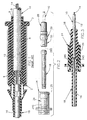
- the currently preferred embodiment of the present invention will now be described in connection with FIGS. 2 and 3.
- the two pieces will be referred to as the molded sleeve 28 and the rotating fitting 24. It should be understood, however, that the outer surface of the rotating fitting 24 could take any form that is suitable for mounting in a fitting.
- the molded sleeve 28 is fastened directly onto and along the longitudinal axis of the conduit 12. As shown in FIGS. 2 and 3, the molded sleeve 28 includes a spherical ball portion 29 for receiving and retaining the rotating fitting 24 and a cylindrical portion 30 for guiding the rotational movement of the rotating fitting 24. The molded sleeve 28 also includes a partial spherical cavity 28s for receiving and supporting a swivel tube 18.
- the rotating fitting 24 includes a spherical cavity 25 receiving the spherical ball 29 of the molded sleeve 28 and a cylindrical cavity 26 for receiving the cylindrical portion 30 of the molded sleeve 28 and maintaining its rotational movement along the axis of the molded sleeve 28 and the conduit 12.
- the rotating fitting may also include a partial spherical cavity or seat 24s for receiving and supporting a swivel tube 18.
- the spherical ball portion 29 of the molded sleeve 28 and the spherical cavity portion 25 of the rotating fitting 24 mate together to form a spherical or annular snap fit. More specifically, the spherical ball portion 29 of the molded sleeve 28 and the spherical cavity portion 25 of the rotating fitting 24 are dimensioned such that when assembled together, their fit ranges from zero clearance to a slight interference condition. By virtue of this zero clearance to slight interference fit between the male and female portion of the annular snap fit, the end fitting does not introduce any extra lash into the assembly through the rotating joint. As a consequence, overall cable travel efficiency is improved in comparison to prior art designs that introduce lash.
- a lubricant is preferably provided on both mating surfaces of the annular snap fit. This obviates the need to provide a circumferential anti-stick surface contiguous with either or both mating surfaces or an anti-stick coating on either or both mating surfaces.
Landscapes
- Engineering & Computer Science (AREA)
- General Engineering & Computer Science (AREA)
- Health & Medical Sciences (AREA)
- Oral & Maxillofacial Surgery (AREA)
- Mechanical Engineering (AREA)
- Flexible Shafts (AREA)
- Details Of Connecting Devices For Male And Female Coupling (AREA)
- Branch Pipes, Bends, And The Like (AREA)
- Joints Allowing Movement (AREA)
Claims (7)
- Kabelkanal-Endanschlussstück, das eine einfache Rotation des Endanschlussstücks relativ zu einer Achse eines Kabelkanals erlaubt, der in einer Fernsteuerungs-Kabelanordnung verwendet wird, wobei das Endanschlussstück umfasst:wobei der teilweise sphärische Kugelabschnitt (29) der Formhülse (28) und der teilweise sphärische Hohlraumabschnitt (25) des rotierenden Anschlussstücks (24) zusammenpassen, um eine teilweise sphärische oder ringförmige Schnapp-Passung zu bilden; undeine Formhülse (28), die direkt auf dem Kabelkanal (12) und längs dessen Achse befestigt ist, wobei die Formhülse (28) einen teilweisen sphärischen Kugelabschnitt (29) und einen zylindrischen Abschnitt (30) enthält;ein rotierendes Anschlussstück (24), das einen teilweisen sphärischen Hohlraumabschnitt (25) zum Aufnehmen des teilweisen sphärischen Abschnitts (29) der Formhülse (28) und einen zylindrischen Hohlraum (26) zum Aufnehmen des zylindrischen Abschnitts (30) der Formhülse (28) umfasst;
wobei der teilweise sphärische Kugelabschnitt (29) der Formhülse (28) und der teilweise sphärische Hohlraumabschnitt (25) des rotierenden Anschlussstücks (24) so bemessen sind, dass dann, wenn sie zusammengefügt sind, das Endanschlussstück keinen zusätzlichen Schlag in die Anordnung durch das rotierende Anschlussstück einführt;
und ein Drehrohr (18), wobei die Formhülse (28) einen teilweise sphärischen Hohlraum (28s) zum Aufnehmen und Unterstützen des Drehrohrs (18) enthält. - Kabelkanal-Endanschlussstück nach Anspruch 1, bei dem der teilweise sphärische Hohlraum (25) durch zwei ausgeprägte Abschnitte der Formhülse (28) und des rotierenden Anschlussstücks (24) gebildet wird.
- Kabelkanal-Endanschlussstück nach Anspruch 1, das femer ein Schmiermittel zwischen den gepaarten Oberflächen der ringförmigen Schnapp-Passung umfasst, um die Montage zu erleichtern und die Rotation des rotierenden Anschlussstücks (24) relativ zur Formhülse (28) zu verbessern.
- Bewegungsübertragungs-Femsteuerungsanordnung des Typs zum Übertragen einer Bewegung längs eines gekrümmten Weges, wobei die Anordnung umfasst:einen Kabelkanal (12), der ein Ende und eine Längsachse aufweist;ein flexibles Bewegungsübertragungs-Kernelement (14), das eine Länge und eine Zentralachse aufweist und längs der Länge innerhalb des Kabelkanals (12) beweglich unterstützt ist; wobei die Anordnung femer ein Kabelkanal-Endanschlussstück nach irgendeinem der Ansprüche 1 bis 3 umfasst.
- Bewegungsübertragungs-Fernsteuerungsanordnung nach Anspruch 4, bei der das rotierende Anschlussstück (24) gegen eine Longitudinalbewegung relativ zur Formhülse (28) fixiert ist.
- Bewegungsübertragungs-Fernsteuerungsanordnung nach Anspruch 4, bei der die teilweise sphärische Hülse (25) durch zwei ausgeprägte Abschnitte der Formhülse (28) und des rotierenden Anschlussstücks (24) gebildet ist.
- Bewegungsübertragungs-Fernsteuerungsanordnung nach Anspruch 4, die ferner ein Schmiermittel zwischen den gepaarten Oberflächen der ringförmigen Schnapp-Passung umfasst, um die Montage zu erleichtern und die Rotation des rotierenden Anschlussstücks (24) relativ zur Formhülse (28) zu verbessern.
Applications Claiming Priority (3)
| Application Number | Priority Date | Filing Date | Title |
|---|---|---|---|
| US08/757,830 US5862710A (en) | 1996-11-27 | 1996-11-27 | Zero lash joint for a rotating conduit fitting for a remote control cable assembly |
| US757830 | 1996-11-27 | ||
| PCT/US1997/021493 WO1998023875A1 (en) | 1996-11-27 | 1997-11-21 | Zero lash joint for a rotating conduit fitting for a remote control cable assembly |
Publications (2)
| Publication Number | Publication Date |
|---|---|
| EP0941413A1 EP0941413A1 (de) | 1999-09-15 |
| EP0941413B1 true EP0941413B1 (de) | 2004-03-24 |
Family
ID=25049389
Family Applications (1)
| Application Number | Title | Priority Date | Filing Date |
|---|---|---|---|
| EP97948491A Expired - Lifetime EP0941413B1 (de) | 1996-11-27 | 1997-11-21 | Spielfreie verbindung für ein drehendes anschlussteil einer betätigungszuganordnung |
Country Status (7)
| Country | Link |
|---|---|
| US (1) | US5862710A (de) |
| EP (1) | EP0941413B1 (de) |
| AT (1) | ATE262652T1 (de) |
| AU (1) | AU5455198A (de) |
| CA (1) | CA2268960A1 (de) |
| DE (1) | DE69728286T2 (de) |
| WO (1) | WO1998023875A1 (de) |
Families Citing this family (19)
| Publication number | Priority date | Publication date | Assignee | Title |
|---|---|---|---|---|
| FR2781714B1 (fr) * | 1998-07-29 | 2000-09-22 | Europ De Fabrications Ind Sefi | Procede pour la fabrication d'un dispositif de commande a distance comprenant un cable de commande mobile dans une gaine |
| FR2782029B1 (fr) * | 1998-08-10 | 2000-10-13 | Valeo Climatisation | Dispositif de commande a distance par cable pour equipement de vehicule automobile |
| DE19846738A1 (de) * | 1998-10-12 | 2000-04-20 | United Parts Fhs Automobil Sys | Anbindungselement für Seilzüge |
| EP1025945B1 (de) * | 1999-02-03 | 2002-12-11 | Trafimet S.P.A. | Kabelmantelbefestigung insbesondere für einen Schweissbrenner mit einem Kugelgelenk zum Anschluss an dem Stromkabel |
| US6189408B1 (en) * | 1999-08-03 | 2001-02-20 | Teleflex Incorporated | Conduit supported swivel tube |
| US6748820B2 (en) | 2000-11-09 | 2004-06-15 | Dura Global Technologies,Inc. | Self-adjusting isolator for reducing cable lash in transmission shift systems |
| EP1291536B1 (de) | 2001-09-11 | 2008-02-13 | Ford Global Technologies, LLC | Vorrichtung zur Befestigung eines langgestreckten Elementes |
| DE10156647B4 (de) * | 2001-11-17 | 2012-09-13 | Volkswagen Ag | Anschlußarmatur für einen Bowdenzugmantel |
| US7559714B2 (en) * | 2002-05-30 | 2009-07-14 | Dura Global Technologies, Inc. | Reverse clip cap terminal connector |
| US20060039748A1 (en) * | 2002-06-07 | 2006-02-23 | Ruhlander Gregory P | Arrangement for connecting a rod end to a headed pin and method of manufacture |
| US6825417B2 (en) * | 2003-01-31 | 2004-11-30 | Daimlerchrysler Corporation | Slide and snap cable end fitting |
| US7770489B2 (en) * | 2003-04-17 | 2010-08-10 | Dura Global Technologies, Llc | Integrated cable connection and shifter housing |
| US20060243086A1 (en) * | 2005-03-16 | 2006-11-02 | Cutkosky Mark R | Power transmission and actuation of a legged robot |
| US7866024B2 (en) * | 2007-09-04 | 2011-01-11 | Dura Global Technologies, Llc | Method of manufacture for a push-pull cable assembly |
| US8418580B2 (en) * | 2007-11-12 | 2013-04-16 | Dura Operating, Llc | Cable assembly |
| US20100275715A1 (en) * | 2009-05-01 | 2010-11-04 | Dura Global Technologies, Inc. | Shift cable assembly and connector therefor |
| GB0919682D0 (en) * | 2009-11-11 | 2009-12-23 | Hi Lex Cable System Company Ltd | Damper |
| CN105299218A (zh) * | 2015-11-02 | 2016-02-03 | 重庆御捷汽车部件有限公司 | 带自动消隙轴承及降噪拉索的手动换挡装置 |
| CN105202173A (zh) * | 2015-11-02 | 2015-12-30 | 重庆御捷汽车部件有限公司 | 带自动消隙轴承及防尘拉索的手动换挡装置 |
Family Cites Families (20)
| Publication number | Priority date | Publication date | Assignee | Title |
|---|---|---|---|---|
| GB978314A (en) * | 1961-04-27 | 1964-12-23 | Bowden Eng Ltd | Improvements in and relating to bowden and like mechanisms |
| CA1146049A (en) * | 1979-01-26 | 1983-05-10 | Teleflex Incorporated | Motion transmitting remote control assembly |
| US4333361A (en) * | 1980-04-25 | 1982-06-08 | Teleflex Incorporated | Remote control (swivel joint) |
| US4386755A (en) * | 1980-06-23 | 1983-06-07 | Teleflex Incorporated | Mold for remote control assembly (vibration dampening) |
| US4406177A (en) * | 1980-06-23 | 1983-09-27 | Teleflex Incorporated | Remote control assembly (vibration dampening) |
| US4348348A (en) * | 1980-06-23 | 1982-09-07 | Teleflex Incorporated | Method for making a remote control assembly with vibration dampener |
| US4537090A (en) * | 1983-12-19 | 1985-08-27 | Eaton Corporation | Vernier control device |
| US4625579A (en) * | 1984-11-28 | 1986-12-02 | Teleflex Incorporated | Capped core element terminal |
| US4763541A (en) * | 1985-11-08 | 1988-08-16 | Teleflex Incorporated | Remote control assembly including side snap in |
| US4793050A (en) * | 1986-07-14 | 1988-12-27 | Teleflex Incorporated | Remote control assembly with improved isolator |
| US4726251A (en) * | 1986-07-14 | 1988-02-23 | Teleflex Incorporated | Remote control assembly with improved isolator |
| US4790205A (en) * | 1986-12-15 | 1988-12-13 | Ford Motor Company | Cable flexible joint |
| US4860609A (en) * | 1988-08-31 | 1989-08-29 | Teleflex Incorporated | Sealed rotating end fitting for a flexible cable |
| FR2644532A1 (fr) * | 1989-03-17 | 1990-09-21 | Teledynamique Sa | Embout de gaine de cable et son procede de fabrication |
| US4951524A (en) * | 1989-07-18 | 1990-08-28 | Teleflex Incorporated | Remote control assembly including rotating slide snap |
| ES2017879A6 (es) * | 1989-12-05 | 1991-03-01 | Pujol & Tarago | Terminal de funda ajustable para cables. |
| US5003838A (en) * | 1990-04-10 | 1991-04-02 | Teleflex Incorporated | Cable routing end fitting assembly |
| US5161428A (en) * | 1991-04-16 | 1992-11-10 | Teleflex Incorporated | Rotatable slider body |
| DE9306761U1 (de) * | 1993-05-05 | 1993-07-01 | Vofa-Werk Xavier Vorbrüggen GmbH & Co KG, 4000 Düsseldorf | Anschlußteil für einen Betätigungszug |
| US5383377A (en) * | 1993-08-25 | 1995-01-24 | Teleflex Incorporated | Rotatable isolated end fitting |
-
1996
- 1996-11-27 US US08/757,830 patent/US5862710A/en not_active Expired - Lifetime
-
1997
- 1997-11-21 CA CA002268960A patent/CA2268960A1/en not_active Abandoned
- 1997-11-21 AT AT97948491T patent/ATE262652T1/de not_active IP Right Cessation
- 1997-11-21 DE DE69728286T patent/DE69728286T2/de not_active Expired - Lifetime
- 1997-11-21 WO PCT/US1997/021493 patent/WO1998023875A1/en not_active Ceased
- 1997-11-21 AU AU54551/98A patent/AU5455198A/en not_active Abandoned
- 1997-11-21 EP EP97948491A patent/EP0941413B1/de not_active Expired - Lifetime
Also Published As
| Publication number | Publication date |
|---|---|
| WO1998023875A1 (en) | 1998-06-04 |
| DE69728286T2 (de) | 2005-04-14 |
| ATE262652T1 (de) | 2004-04-15 |
| EP0941413A1 (de) | 1999-09-15 |
| AU5455198A (en) | 1998-06-22 |
| DE69728286D1 (de) | 2004-04-29 |
| US5862710A (en) | 1999-01-26 |
| CA2268960A1 (en) | 1998-06-04 |
Similar Documents
| Publication | Publication Date | Title |
|---|---|---|
| US5884531A (en) | Low lash rotating conduit end fitting for a remote control cable assembly that isolates against vibration/noise transmission | |
| US5862710A (en) | Zero lash joint for a rotating conduit fitting for a remote control cable assembly | |
| WO1998023875A9 (en) | Zero lash joint for a rotating conduit fitting for a remote control cable assembly | |
| US5575180A (en) | Core and conduit splicer | |
| CA2128744C (en) | Rotatable isolated end fitting | |
| US6748820B2 (en) | Self-adjusting isolator for reducing cable lash in transmission shift systems | |
| EP0651165B1 (de) | Feinbedienungseinrichtung mit Schwingungsdämpfer | |
| US8418580B2 (en) | Cable assembly | |
| US8146455B2 (en) | Reverse clip cap terminal connector | |
| US8516921B2 (en) | Cable assembly with multi-directional connector | |
| US4753123A (en) | Automatic self adjusting cable control device | |
| US20100275715A1 (en) | Shift cable assembly and connector therefor | |
| EP1469209B1 (de) | Kabelverbindung und Betätigungsgehäuse | |
| US7353728B2 (en) | Conduit end fitting | |
| EP2404070A1 (de) | Verankerungsvorrichtung für ein übertragungskabel | |
| WO1998023874A1 (en) | End fitting for a remote control cable assembly with vibration transmission isolation | |
| EP2220386B1 (de) | Verbindungsvorrichtung für ein getriebekabel in einem fahrzeug | |
| EP0635103A1 (de) | Miniaturstellvorrichtung für kabelseele | |
| CA2202327C (en) | Mid-length adjustment and method of assembly | |
| WO2007062389A9 (en) | Two-piece vibration dampener |
Legal Events
| Date | Code | Title | Description |
|---|---|---|---|
| PUAI | Public reference made under article 153(3) epc to a published international application that has entered the european phase |
Free format text: ORIGINAL CODE: 0009012 |
|
| 17P | Request for examination filed |
Effective date: 19990503 |
|
| AK | Designated contracting states |
Kind code of ref document: A1 Designated state(s): AT BE CH DE DK ES FI FR GB GR IE IT LI LU MC NL PT SE |
|
| 17Q | First examination report despatched |
Effective date: 20021030 |
|
| GRAP | Despatch of communication of intention to grant a patent |
Free format text: ORIGINAL CODE: EPIDOSNIGR1 |
|
| GRAS | Grant fee paid |
Free format text: ORIGINAL CODE: EPIDOSNIGR3 |
|
| GRAA | (expected) grant |
Free format text: ORIGINAL CODE: 0009210 |
|
| AK | Designated contracting states |
Kind code of ref document: B1 Designated state(s): AT BE CH DE DK ES FI FR GB GR IE IT LI LU MC NL PT SE |
|
| PG25 | Lapsed in a contracting state [announced via postgrant information from national office to epo] |
Ref country code: NL Free format text: LAPSE BECAUSE OF FAILURE TO SUBMIT A TRANSLATION OF THE DESCRIPTION OR TO PAY THE FEE WITHIN THE PRESCRIBED TIME-LIMIT Effective date: 20040324 Ref country code: LI Free format text: LAPSE BECAUSE OF FAILURE TO SUBMIT A TRANSLATION OF THE DESCRIPTION OR TO PAY THE FEE WITHIN THE PRESCRIBED TIME-LIMIT Effective date: 20040324 Ref country code: IT Free format text: LAPSE BECAUSE OF FAILURE TO SUBMIT A TRANSLATION OF THE DESCRIPTION OR TO PAY THE FEE WITHIN THE PRESCRIBED TIME-LIMIT;WARNING: LAPSES OF ITALIAN PATENTS WITH EFFECTIVE DATE BEFORE 2007 MAY HAVE OCCURRED AT ANY TIME BEFORE 2007. THE CORRECT EFFECTIVE DATE MAY BE DIFFERENT FROM THE ONE RECORDED. Effective date: 20040324 Ref country code: FI Free format text: LAPSE BECAUSE OF FAILURE TO SUBMIT A TRANSLATION OF THE DESCRIPTION OR TO PAY THE FEE WITHIN THE PRESCRIBED TIME-LIMIT Effective date: 20040324 Ref country code: CH Free format text: LAPSE BECAUSE OF FAILURE TO SUBMIT A TRANSLATION OF THE DESCRIPTION OR TO PAY THE FEE WITHIN THE PRESCRIBED TIME-LIMIT Effective date: 20040324 Ref country code: BE Free format text: LAPSE BECAUSE OF FAILURE TO SUBMIT A TRANSLATION OF THE DESCRIPTION OR TO PAY THE FEE WITHIN THE PRESCRIBED TIME-LIMIT Effective date: 20040324 Ref country code: AT Free format text: LAPSE BECAUSE OF FAILURE TO SUBMIT A TRANSLATION OF THE DESCRIPTION OR TO PAY THE FEE WITHIN THE PRESCRIBED TIME-LIMIT Effective date: 20040324 |
|
| REG | Reference to a national code |
Ref country code: GB Ref legal event code: FG4D |
|
| REG | Reference to a national code |
Ref country code: CH Ref legal event code: EP |
|
| REG | Reference to a national code |
Ref country code: IE Ref legal event code: FG4D |
|
| REF | Corresponds to: |
Ref document number: 69728286 Country of ref document: DE Date of ref document: 20040429 Kind code of ref document: P |
|
| PG25 | Lapsed in a contracting state [announced via postgrant information from national office to epo] |
Ref country code: SE Free format text: LAPSE BECAUSE OF FAILURE TO SUBMIT A TRANSLATION OF THE DESCRIPTION OR TO PAY THE FEE WITHIN THE PRESCRIBED TIME-LIMIT Effective date: 20040624 Ref country code: GR Free format text: LAPSE BECAUSE OF FAILURE TO SUBMIT A TRANSLATION OF THE DESCRIPTION OR TO PAY THE FEE WITHIN THE PRESCRIBED TIME-LIMIT Effective date: 20040624 Ref country code: DK Free format text: LAPSE BECAUSE OF FAILURE TO SUBMIT A TRANSLATION OF THE DESCRIPTION OR TO PAY THE FEE WITHIN THE PRESCRIBED TIME-LIMIT Effective date: 20040624 |
|
| PG25 | Lapsed in a contracting state [announced via postgrant information from national office to epo] |
Ref country code: ES Free format text: LAPSE BECAUSE OF FAILURE TO SUBMIT A TRANSLATION OF THE DESCRIPTION OR TO PAY THE FEE WITHIN THE PRESCRIBED TIME-LIMIT Effective date: 20040705 |
|
| NLV1 | Nl: lapsed or annulled due to failure to fulfill the requirements of art. 29p and 29m of the patents act | ||
| REG | Reference to a national code |
Ref country code: CH Ref legal event code: PL |
|
| PG25 | Lapsed in a contracting state [announced via postgrant information from national office to epo] |
Ref country code: LU Free format text: LAPSE BECAUSE OF NON-PAYMENT OF DUE FEES Effective date: 20041121 |
|
| PG25 | Lapsed in a contracting state [announced via postgrant information from national office to epo] |
Ref country code: IE Free format text: LAPSE BECAUSE OF NON-PAYMENT OF DUE FEES Effective date: 20041122 |
|
| PG25 | Lapsed in a contracting state [announced via postgrant information from national office to epo] |
Ref country code: MC Free format text: LAPSE BECAUSE OF NON-PAYMENT OF DUE FEES Effective date: 20041130 |
|
| ET | Fr: translation filed | ||
| PLBE | No opposition filed within time limit |
Free format text: ORIGINAL CODE: 0009261 |
|
| STAA | Information on the status of an ep patent application or granted ep patent |
Free format text: STATUS: NO OPPOSITION FILED WITHIN TIME LIMIT |
|
| 26N | No opposition filed |
Effective date: 20041228 |
|
| REG | Reference to a national code |
Ref country code: IE Ref legal event code: MM4A |
|
| PG25 | Lapsed in a contracting state [announced via postgrant information from national office to epo] |
Ref country code: PT Free format text: LAPSE BECAUSE OF NON-PAYMENT OF DUE FEES Effective date: 20040824 |
|
| PGFP | Annual fee paid to national office [announced via postgrant information from national office to epo] |
Ref country code: FR Payment date: 20141118 Year of fee payment: 18 Ref country code: DE Payment date: 20141128 Year of fee payment: 18 Ref country code: GB Payment date: 20141127 Year of fee payment: 18 |
|
| REG | Reference to a national code |
Ref country code: DE Ref legal event code: R119 Ref document number: 69728286 Country of ref document: DE |
|
| GBPC | Gb: european patent ceased through non-payment of renewal fee |
Effective date: 20151121 |
|
| REG | Reference to a national code |
Ref country code: FR Ref legal event code: ST Effective date: 20160729 |
|
| PG25 | Lapsed in a contracting state [announced via postgrant information from national office to epo] |
Ref country code: DE Free format text: LAPSE BECAUSE OF NON-PAYMENT OF DUE FEES Effective date: 20160601 Ref country code: GB Free format text: LAPSE BECAUSE OF NON-PAYMENT OF DUE FEES Effective date: 20151121 |
|
| PG25 | Lapsed in a contracting state [announced via postgrant information from national office to epo] |
Ref country code: FR Free format text: LAPSE BECAUSE OF NON-PAYMENT OF DUE FEES Effective date: 20151130 |