EP0941504B1 - Procede pour parametrer un automate a logique floue qui compare un signal de mesure a un signal modele - Google Patents
Procede pour parametrer un automate a logique floue qui compare un signal de mesure a un signal modele Download PDFInfo
- Publication number
- EP0941504B1 EP0941504B1 EP97949948A EP97949948A EP0941504B1 EP 0941504 B1 EP0941504 B1 EP 0941504B1 EP 97949948 A EP97949948 A EP 97949948A EP 97949948 A EP97949948 A EP 97949948A EP 0941504 B1 EP0941504 B1 EP 0941504B1
- Authority
- EP
- European Patent Office
- Prior art keywords
- processing state
- control device
- fuzzy
- pattern signal
- fuzzy automatic
- Prior art date
- Legal status (The legal status is an assumption and is not a legal conclusion. Google has not performed a legal analysis and makes no representation as to the accuracy of the status listed.)
- Expired - Lifetime
Links
Images


Classifications
-
- G—PHYSICS
- G06—COMPUTING OR CALCULATING; COUNTING
- G06N—COMPUTING ARRANGEMENTS BASED ON SPECIFIC COMPUTATIONAL MODELS
- G06N7/00—Computing arrangements based on specific mathematical models
- G06N7/02—Computing arrangements based on specific mathematical models using fuzzy logic
- G06N7/023—Learning or tuning the parameters of a fuzzy system
-
- B—PERFORMING OPERATIONS; TRANSPORTING
- B22—CASTING; POWDER METALLURGY
- B22D—CASTING OF METALS; CASTING OF OTHER SUBSTANCES BY THE SAME PROCESSES OR DEVICES
- B22D11/00—Continuous casting of metals, i.e. casting in indefinite lengths
- B22D11/16—Controlling or regulating processes or operations
-
- Y—GENERAL TAGGING OF NEW TECHNOLOGICAL DEVELOPMENTS; GENERAL TAGGING OF CROSS-SECTIONAL TECHNOLOGIES SPANNING OVER SEVERAL SECTIONS OF THE IPC; TECHNICAL SUBJECTS COVERED BY FORMER USPC CROSS-REFERENCE ART COLLECTIONS [XRACs] AND DIGESTS
- Y10—TECHNICAL SUBJECTS COVERED BY FORMER USPC
- Y10S—TECHNICAL SUBJECTS COVERED BY FORMER USPC CROSS-REFERENCE ART COLLECTIONS [XRACs] AND DIGESTS
- Y10S706/00—Data processing: artificial intelligence
- Y10S706/902—Application using ai with detail of the ai system
- Y10S706/903—Control
Definitions
- WO 96/31 304 describes a device for early breakthrough detection known in continuous casting plants.
- For early detection of breakthroughs becomes the surface temperature of the cast strand with the help of temperature sensors in a mold around the Strands are arranged distributed around, captured and then evaluated. There is one for each of the temperature sensors
- Pattern recognition device assigned from the detected Temperature and one representing the previous temperature profile internal state quantity based on Fuzzy inferences updated and the inner state variable a current prediction value for the breakthrough probability on the output side generated.
- the pattern recognition facility is a fuzzy set of rules based on fuzzy logic implemented.
- the fuzzy rules are tabular Rules listed which are based on linguistic values of the Input variables, such as temperature based.
- the rules determine under what conditions the pattern recognition device the internal state, i.e. the processing status of the fuzzy set of rules and thus the current prediction value for the breakthrough probability changed or maintained.
- the disadvantage of the known pattern recognition device is that that the creation of those implemented in fuzzy logic Fuzzy rules, made "by hand” by a specialist must become. As for every processing state of the fuzzy set of rules to design a complete set of rules parameterization of the fuzzy logic the known pattern recognition device cumbersome and time consuming.
- Another disadvantage is that one with rules parameterized fuzzy logic of the pattern recognition device only is able to recognize a certain pattern. If the pattern recognition device is a new, different pattern recognize, for example after a change of Continuous casting plant, so again must be manually by one Specialist and based on his specialist knowledge new rules for Parameterization of the fuzzy logic can be designed.
- the invention is based on the object of a method for parameterizing a for comparing a measurement signal with a fuzzy automaton serving a pattern signal by means of a program-controlled arithmetic unit.
- the object is achieved with the one specified in claim 1 Process, and the use specified in claim 10 of the procedure for a device for early breakthrough detection in continuous casting plants.
- the solution according to the invention for parameterizing a fuzzy machine has the advantage that its parameterization in the form the creation of transformation rules by the calculator can be done fully automatically.
- the calculator must the pattern signal or the pattern signals to be recognized can be specified so that parameters can be set can.
- the parameterization of the fuzzy machine according to the invention has in particular the advantage that with frequently changing Sample signals a quick, uncomplicated and flexible re-parameterization of the fuzzy machine can be done.
- the "record" a pattern signal in the fuzzy machine can thus can also be carried out without special expertise.
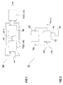
- Figure 1 shows an example of a basic structure MA Fuzzy automatons with an input vector u (i).
- a first one Fuzzy logic F (z (i), u (i)) generated from the input vector u (i) and a buffered inner state vector z (i) an updated state vector z (i + 1), which in a Memory element MZ is buffered.
- the cached State vector z (i) and the input vector u (i) become one in a second fuzzy logic G (z (i), u (i)) Output vector y (i) linked together.
- FIG. 2 shows an example of a fuzzy machine FA with a Fuzzy logic FZ shown.
- the input vector u (i) in the example in FIG. 2 from the input variables of a first one Signal u (t) and a second signal u '(t), which for example the derivative of the first signal u (t) after the Time is.
- FIG. 2 shows an example of a fuzzy machine FA with a Fuzzy logic FZ shown.
- FIG. 2 shows the basic structure MA of a fuzzy machine FA, the first fuzzy logic F (z (i), u (i)) and the second fuzzy logic G (z (i), u (i
- the cached inner state vector P (i) corresponds to the detection probability that already a certain waveform of the input variables u (t) and u '(t) is present. According to the invention, this is achieved by a corresponding Parameterization PA of the fuzzy logic FZ using a program-controlled calculator RE causes.
- the fuzzy machine FA and the program-controlled arithmetic unit RE can be implemented both as hardware or as software.
- the fuzzy automaton FA and the arithmetic unit RE can in particular as separate units, but preferably also in a single device, for example through two computer programs installed on a computer.
- the fuzzy machine FA shown in FIG. 2 acts it is a fuzzy machine of the type "Sugeno".
- the fuzzy logic FZ has in particular one Fuzzification of the input variables based on a set of rules and in particular a subsequent defuzzification as Degree of recognition P (i + 1) is output. This is preferably done Inference according to the max-min method and defuzzification according to the focus method for singletons.
- the degree of recognition P (i + 1) is a measure of the probability that a certain signal curve defined by the parameterization PA of the input variables u (t) and u '(t).
- the fuzzy logic FZ can make a comparison between the Actual values of the input variables u (t) and u '(t) and that with the Parameterization PA defined course of the pattern signal carry out.
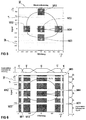
- FIG. 3 shows an example of a fuzzy state graph of the Fuzzy automaton FA shown.
- the nodes of the state graph form the possible processing states Z1, Z2, .., Zn-1, Zn, in which the fuzzy machine FA is located can.
- the higher the respective processing status Z1..Zn the fuzzy machine FA is in the more the greater the probability that a certain one is already Signal waveform of the input variables u (t) and u '(t) is present.
- the processing states Z1..Zn especially referred to as "out of focus” or "fuzzy” because of the fuzzy automaton FA in contrast to binary automatons several Editing states simultaneously with a specific one Probability share can be accepted.
- the transition conditions between the individual processing states Zl..Zn of the fuzzy automaton FA through transformation rules described in FIG. 3 represented by arrows with the reference symbols A1..An-1, B2, .., Dn are.
- the transformation regulations lay down determines whether the fuzzy machine FA maintains its processing status or changes. Set the transformation rules in particular from transition rules A1..An-1 which the fuzzy automaton FA from one current to another next higher processing state passes, holding rules B2..Bn-1, in which the fuzzy machine FA in a current Processing status remains, return rules C3..Cn-1, at which the fuzzy automaton FA from one current to another jumps back to the next lower processing state, and Reset rules D1..Dn, in which the fuzzy machine FA by one current in the lowest, i.e. first processing state Z1 jumps back.
- FIG. 4 shows an example of the signal curve of a Signal f and its derivative f 'given over time.
- the signals f and f ' are preferably given scaled scaled and are used for parameterization in the following embodiment of the fuzzy machine FA shown in FIG. 2. This is used to compare a measurement signal, for example the actual values of the input variables u (t) and u '(t), with a pattern signal.
- a measurement signal for example the actual values of the input variables u (t) and u '(t)
- the pattern signal formed by the signals f and f ' shown.
- the pattern signal is not necessarily composed of one Basic signal and its first derivative together, but can also have higher derivatives or further signals.
- the program-controlled arithmetic unit selects RE points K1..K7 in the course of the pattern signal.
- the selected ones Points K1..K7 are also used as indicators of the pattern signal.
- the points can, for example arbitrarily selected or equidistant to the course points taken from the pattern signal.
- the calculator RE determines the selected points K1..K7 in such a way that this for its course of the pattern signal are characteristic.
- the selected ones Points K1..K7 of the waveform of the pattern signal mathematically characteristic properties.
- extreme values zeros and / or turning points.
- 4 are those points K1..K7 of the pattern signal forming signals f and f 'selected, in which the signal f or its derivative f 'at a time Have an extreme value or a zero.
- Each of the points K1..K7 selected as an example in FIG. 4 is according to the invention by the program-controlled shown in Figure 2 Calculator RE a processing state Zl..Zn assigned to the fuzzy automaton FA, so that this by means of a thereby formed sequence of processing states Zl..Zn Measure for the probability that one emerges from the Input signals u (t), u '(t) composing measurement signal corresponding course, such as an example from the Has input variables f, f 'composing pattern signal.
- the signals f and f ' Composing pattern signal of Figure 4 thus result eight processing states Z1..Z8 of the fuzzy machine FA.
- the fuzzy machine FA moves within the sequence of the processing states Z1..Z8, which is shown in Figure 3 are.
- the processing states Z1..Z8 correspond to the selected already recognized by the fuzzy automaton FA Points K1..K7 of the signals f and f '.
- the fuzzy machine FA takes the highest processing state Zn or Z8, this has in measurement signal to be analyzed corresponds to the sample signal History recognized.
- FIG. 5 shows the signals shown in FIG. 4 f and f 'in the form of a trajectory-shaped pattern signal T shown.
- the pattern signal T is through the program-controlled arithmetic unit RE in an input value range M of the fuzzy machine FA shown.
- the program-controlled calculator RE selected points K1..K7 mapped and so-called Characteristic areas M34, M53, M32, M23 in the input value area M generated in such a way that at least the selected points K1..K7.
- the selected points K1..K7 are not shown in dots, but as feature areas M33 shown in gray, M34, M53, M32, M23 delimited.
- the Feature area M53 to a maximum and the feature area M23 to a minimum of the signal f, or a zero of the signal f '.
- the normalized input value range M is off of Figure 5 shown again.
- the program-controlled arithmetic unit RE for better recording of Course of the pattern signal T including the selected ones
- Points K1..K7 delimiting feature areas M33, M34, M53, M32, M23 further feature areas shown in gray M11..M65 generated. 6 lies between them transition areas shown in white by grid lines, so that the normalized input value range M is complete covered by feature areas M11..M65 and transition areas is.
- the feature areas M11..M65 are defined by the program-controlled arithmetic unit RE in particular membership functions f1..f6, f1 '.. f5' of the fuzzy logic shown in FIG. 2 FZ assigned.
- the feature areas represent M11..M65 in particular the core area of membership functions f1..f6, f1 '.. f5', in which these have the value 1.
- the grid lines shown in FIG. 6 each lie at the boundaries of the core areas of membership functions f1..f6, f1 '.. f5'.
- the individual membership functions f1..f6, f1 '.. f5' merge linearly in the edge areas over, so that their sum is just 1.
- the reference symbols are exemplary here as linguistic variables f1..f6 and f1 '.. f5', which are given below also for specifying the coordinates of the feature areas M11..M65 can be used.
- FIGS. 7a to 7h are examples of diagrams showing the Karnaugh diagrams correspond to Bodesch's logic, that of the invention created by the program-controlled calculator RE Transformation instructions for the individual processing states Z1..Z8 of the fuzzy machine FA shown.
- the program-controlled arithmetic unit RE for parameterization PA of the fuzzy machine FA every processing state Z1..Z8 for each characteristic area M11..M65 of the input value range M a transformation rule to which in Figures 7a to 7h by the reference numerals Z1..Z8, f1..f6, f1 '.. f5', A1..An-1, B2..Bn-1, C3..Cn-1, D1..Dn are shown.
- the parameterization PA of the fuzzy machine takes place FA by the program-controlled calculator RE, which starting from a first processing state Z1 of the fuzzy machine FA along the course of the pattern signal T die Sequence of the feature ranges M11..M65 determined by the sample signal T be run through.
- Figures 7a to 7h are the transformation regulations Z1..Z8, for example, f1..f6, f1 '.. f5' for the respective processing states Z1..Z8 of the fuzzy machine FA shown.
- the program-controlled arithmetic unit RE from the entirety of Feature areas M11..M65 the feature areas M23, M32, M33, M34, M53, in which a selected point K1..K7 of the pattern signal T lies.
- the feature area M33 determines where the last selected point K7 of the pattern signal T lies and the feature areas M22, M24, M42, M44 selected, in which no selected point K1..K7 des Pattern signal T is.
- all transformation rules of the processing states Z1..Z8 through the program-controlled arithmetic unit RE is initially determined by reset rules D1..D8 that the fuzzy machine FA in the first processing state Z1 jumps back. This will later cause the fuzzy machine FA if a measurement signal to be analyzed deviates u (t), u '(t) from the pattern signal T back to the initial state Z1 is reset.
- the fuzzy machine FA is initially in the processing state Z1.
- the first selected point K1 is recognized in the field f3 / f3 'in the measurement signal to be analyzed by the program-controlled Calculator RE should change the processing state of the fuzzy machine FA in the next higher processing state Z2 take place.
- the transformation regulation in Field f3 / f3 'of the first processing state Z1 therefore causes using the transition rule A1 the transition of the fuzzy machine FA in the next higher, second processing state Z2.
- second processing state Z2 causes the transformation rule in field f3 / f3 'by means of the hold rule B2 the whereabouts of the fuzzy machine FA in this next higher, second processing state Z2.
- third processing state Z3 causes the transformation rule in field f3 / f3 'using the return rule C3 the return of the fuzzy machine FA to the second processing state Z2.
- the profile of the pattern signal intersects T in the third processing state Z3 one by Field f4 / f4 'represent the characteristic area without there a selected point K1..K7 of the pattern signal T lies.
- the Transformation rule in field f4 / f4 'of the third processing state Z3 therefore uses the holding rule B3 the fuzzy machine FA remaining in the current, third processing state Z3.
- fourth processing state Z4 effects the transformation rule in the field f4 / f4 'by means of the return rule C4 the return of the fuzzy automaton FA in the third processing state Z3.
- the program-controlled calculator RE is advantageous for the case in which the pattern signal T has passed Sequence of the characteristic ranges M11..M65 in the input value range M two successive feature areas M11..M65 diagonally are arranged to each other, at least the corresponding Transformation regulations in this regard in between and of which feature areas M11..M65 lying on the side in the current Processing status so that the fuzzy machine FA remains in this.
- These are in particular the characteristic areas M11..M65, which are in the area of a rectangle, which by the two consecutive, diagonally to each other arranged feature areas M11..M65 as corner areas is spanned.
- the fuzzy automaton is in the current processing state jumps back.
- This is the procedure in a device for early breakthrough detection used in continuous casting plants.
- This points Pattern signal T at least the course of a breakthrough of Cast strand leading temperature signal.
- the one to be analyzed Measurement signal u (t), u '(t) has at least the actual value the temperature of the cast strand.
Landscapes
- Engineering & Computer Science (AREA)
- Software Systems (AREA)
- Physics & Mathematics (AREA)
- Automation & Control Theory (AREA)
- Fuzzy Systems (AREA)
- Theoretical Computer Science (AREA)
- General Physics & Mathematics (AREA)
- Evolutionary Computation (AREA)
- Pure & Applied Mathematics (AREA)
- General Health & Medical Sciences (AREA)
- Algebra (AREA)
- Artificial Intelligence (AREA)
- Computational Mathematics (AREA)
- Data Mining & Analysis (AREA)
- Biomedical Technology (AREA)
- Life Sciences & Earth Sciences (AREA)
- Mathematical Analysis (AREA)
- Mathematical Optimization (AREA)
- Molecular Biology (AREA)
- Computing Systems (AREA)
- General Engineering & Computer Science (AREA)
- Mathematical Physics (AREA)
- Health & Medical Sciences (AREA)
- Mechanical Engineering (AREA)
- Feedback Control In General (AREA)
- Injection Moulding Of Plastics Or The Like (AREA)
- Image Analysis (AREA)
- Continuous Casting (AREA)
- Testing And Monitoring For Control Systems (AREA)
- Testing Electric Properties And Detecting Electric Faults (AREA)
Claims (11)
- Procédé pour le paramétrage (PA) d'un automate à logique floue (FA) servant à comparer un signal de mesure (u(t), u'(t)) à un signal modèle (T, f, f'), au moyen d'une unité de calcul commandée par programme (RE) quia) sélectionne des points (K1 à K7) dans la courbe du signal modèle (T, f, f'),b) reproduit le signal modèle (T, f, f') dans une zone de valeurs d'entrée (M) de l'automate à logique floue (FA),c) génère des zones caractéristiques (M11 à M65) dans la zone de valeurs d'entrée (M) de telle sorte qu'au moins les points sélectionnés (K1 à K7) se trouvent dans celles-ci,d) associe à chaque point sélectionné (K1 à K7) un état de traitement (Z1 à Zn) de l'automate à logique floue (FA) de telle sorte que celui-ci détermine au moyen d'une séquence ainsi formée des états de traitement (Z1 à Zn) une mesure pour le fait que le signal de mesure (u(t), u'(t)) a une allure correspondante comme le signal modèle (T, f, f'),e) pour le paramétrage (PA) de l'automate à logique floue (FA), associe à chaque état de traitement (Z1 à Zn) pour chaque zone caractéristique (M11 à M65) de la zone de valeurs d'entrée (M) une règle de transformation (Z1 à Z8, f1 à f6, f1' à f5', A1 à An-1, B2 à Bn-1, C3 à Cn-1, D1 à Dn) que l'automate à logique floue (FA) exécute en fonction de son état actuel de traitement (Z1 à Zn) pour la transition dans un état de traitement suivant (Z1 à Zn) lors du passage du signal de mesure à analyser (u(t), u'(t)) par une zone caractéristique (M11 à M65).
- Procédé selon la revendication 1, dans lequel, à partir d'un premier état de traitement (Z1) de l'automate à logique floue (FA), l'unité de calcul commandée par programme (RE) détermine le long de la courbe du signal modèle (T, f, f') la séquence des zones caractéristiques (M11 à M65) qui sont traversées par le signal modèle (T, f, f') eta) sélectionne à partir de là les zones caractéristiques (M23, M32, M33, M34, M53) dans lesquelles se trouve un point sélectionné (K1 à K7) du signal modèle (T, f, f'), etb) sélectionne à partir de là la zone caractéristique (M33) dans laquelle se trouve le dernier point sélectionné (K7) du signal modèle (T, f, f').
- Procédé selon la revendication 2, dans lequel l'unité de calcul commandée par programme (RE) fixe d'abord les règles de transformation (Z1 à Z8, f1 à f6, f1' à f5', A1 à An-1, B2 à Bn-1, C3 à Cn-1, D1 à Dn) des états de traitement (Z1 à Zn) de telle sorte que l'automate à logique floue (FA) revient dans le premier état de traitement (Z1).
- Procédé selon la revendication 3, dans lequel, pour le cas où un point sélectionné (K1 à K7) du signal modèle (T, f, f') se trouve dans une zone caractéristique sélectionnée (M23, M32, M33, M34, M53), l'unité de calcul commandée par programme (RE)a) fixe la règle de transformation correspondante (Z1 à Z8, f1 à f6, f1' à f5', A1 à An-1, B2 à Bn-1, C3 à Cn-1, D1 à Dn) de l'état de traitement actuel (Zk) de telle sorte que l'automate à logique floue (FA) passe dans l'état de traitement immédiatement supérieur (Zk+1),b) fixe la règle de transformation correspondante (Z1 à Z8, f1 à f6, f1' à f5', A1 à An-1, B2 à Bn-1, C3 à Cn-1, D1 à Dn) de l'état de traitement immédiatement supérieur (Zk+1) de telle sorte que l'automate à logique floue (FA) reste dans l'état de traitement immédiatement supérieur (Zk+1),c) fixe la règle de transformation correspondante (Z1 à Z8, f1 à f6, f1' à f5', A1 à An-1, B2 à Bn-1, C3 à Cn-1, D1 à Dn) de l'état de traitement supérieur à celui immédiatement supérieur (Zk+2) de telle sorte que l'automate à logique floue (FA) revient dans l'état de traitement immédiatement supérieur (Zk+1), etd) pour fixer d'autres règles de transformation (Z1 à Z8, f1 à f6, f1' à f5', A1 à An-1, B2 à Bn-1, C3 à Cn-1, D1 à Dn), utilise l'état de traitement immédiatement supérieur (Zk+1) de l'automate à logique floue (FA) comme nouvel état de traitement actuel.
- Procédé selon l'une des revendications 3 ou 4, dans lequel, pour le cas où le dernier point sélectionné (K7) du signal modèle (T, f, f') se trouve dans une zone caractéristique sélectionnée (M33), l'unité de calcul commandée par programme (RE)a) fixe la règle de transformation correspondante (Z7, f1 à f6, f1' à f5', A7, B7, C7, D7) de l'état de traitement actuel (Z7) de telle sorte que l'automate à logique floue (FA) passe dans l'état de traitement immédiatement supérieur (Z8), etb) fixe toutes les autres règles de transformation (Z8, f1 à f6, f1' à f5', D8) de l'état de traitement immédiatement supérieur (Z8) de telle sorte que l'automate à logique floue (FA) revient dans le premier état de traitement (Z1).
- Procédé selon l'une des revendications 3 à 5, dans lequel, pour le cas où aucun point sélectionné (K1 à K7) du signal modèle (T, f, f') ne se trouve dans une zone caractéristique sélectionnée (M22, M24, M42, M44), l'unité de calcul commandée par programme (RE)a) fixe la règle de transformation correspondante (Z1 à Z8, f1 à f6, f1' à f5', A1 à An-1, B2 à Bn-1, C3 à Cn-1, D1 à Dn) de l'état de traitement actuel (Zk) de telle sorte que l'automate à logique floue (FA) reste dans l'état de traitement actuel (Zk), etb) fixe la règle de transformation correspondante (Z1 à Z8, f1 à f6, f1' à f5', A1 à An-1, B2 à Bn-1, C3 à Cn-1, D1 à Dn) de l'état de traitement immédiatement supérieur (Zk+1) de telle sorte que l'automate à logique floue (FA) revient dans l'état de traitement actuel (Zk).
- Procédé selon l'une des revendications 3 à 6, dans lequel, pour le cas où, dans la séquence des zones caractéristiques (M11 à M65) qui est parcourue par le signal modèle (T, f, f'), deux zones caractéristiques successives (M11 à M65) sont disposées en diagonale l'une par rapport à l'autre dans la zone de valeurs d'entrée (M), l'unité de calcul commandée par programme (RE) fixe au moins les règles de transformation correspondantes (Z1 à Z8, f1 à f6, f1' à f5', A1 à An-1, B2 à Bn-1, C3 à Cn-1, D1 à Dn) des zones caractéristiques (M11 à M65) se trouvant entre et latéralement par rapport à celles-ci dans la zone de valeurs d'entrée (M)a) dans l'état de traitement actuel (Zk) de telle sorte que l'automate à logique floue (FA) reste dans l'état de traitement actuel (Zk), etb) dans l'état de traitement immédiatement supérieur (Zk+1) de telle sorte que l'automate à logique floue (FA) revient dans l'état de traitement actuel (Zk).
- Procédé selon l'une des revendications précédentes, dans lequel l'unité de calcul commandée par programme (RE) associe aux zones caractéristiques (M11 à M65) dans la zone de valeurs d'entrée (M) des fonctions d'appartenance (f1 à f6, f1' à f5') de l'automate à logique floue (FA).
- Procédé selon l'une des revendications précédentes, dans lequel le signal modèle (T, f, f') présente une courbe de signal (f) et au moins une dérivée mathématique (f') de la courbe de signal (f), notamment en fonction du temps.
- Procédé selon l'une des revendications précédentes, dans lequel l'unité de calcul commandée par programme (RE) détermine les points sélectionnés (K1 à K7) de telle sorte que ceux-ci sont caractéristiques de la courbe du signal modèle (T, f, f').
- Utilisation du procédé selon l'une des revendications précédentes dans un dispositif pour la détection précoce de ruptures dans des installations de coulée continue,a) le signal modèle (T, f, f') comportant au moins la courbe temporelle d'un signal de température conduisant à la rupture de la coulée continue, etb) le signal de mesure (u(t), u'(t)) comportant au moins la valeur réelle de la température de la coulée continue.
Applications Claiming Priority (3)
| Application Number | Priority Date | Filing Date | Title |
|---|---|---|---|
| DE19649438 | 1996-11-28 | ||
| DE19649438 | 1996-11-28 | ||
| PCT/DE1997/002703 WO1998024009A1 (fr) | 1996-11-28 | 1997-11-18 | Procede pour parametrer un automate a logique floue qui compare un signal de mesure a un signal modele |
Publications (2)
| Publication Number | Publication Date |
|---|---|
| EP0941504A1 EP0941504A1 (fr) | 1999-09-15 |
| EP0941504B1 true EP0941504B1 (fr) | 2001-03-28 |
Family
ID=7813090
Family Applications (1)
| Application Number | Title | Priority Date | Filing Date |
|---|---|---|---|
| EP97949948A Expired - Lifetime EP0941504B1 (fr) | 1996-11-28 | 1997-11-18 | Procede pour parametrer un automate a logique floue qui compare un signal de mesure a un signal modele |
Country Status (8)
| Country | Link |
|---|---|
| US (1) | US6345206B1 (fr) |
| EP (1) | EP0941504B1 (fr) |
| JP (1) | JP2001504621A (fr) |
| AT (1) | ATE200155T1 (fr) |
| AU (1) | AU731116B2 (fr) |
| CA (1) | CA2273330A1 (fr) |
| DE (1) | DE59703251D1 (fr) |
| WO (1) | WO1998024009A1 (fr) |
Families Citing this family (2)
| Publication number | Priority date | Publication date | Assignee | Title |
|---|---|---|---|---|
| DE10027324C2 (de) * | 1999-06-07 | 2003-04-10 | Sms Demag Ag | Verfahren zum Gießen eines metallischen Strangs sowie System hierzu |
| US7634477B2 (en) * | 2002-09-18 | 2009-12-15 | Netezza Corporation | Asymmetric data streaming architecture having autonomous and asynchronous job processing unit |
Family Cites Families (12)
| Publication number | Priority date | Publication date | Assignee | Title |
|---|---|---|---|---|
| US5303385A (en) * | 1989-03-17 | 1994-04-12 | Hitachi, Ltd. | Control system having optimality decision means |
| US5930136A (en) * | 1990-06-04 | 1999-07-27 | Hitachi, Ltd. | Control device for controlling a controlled apparatus, and a control method therefor |
| JPH0722811B2 (ja) * | 1990-11-02 | 1995-03-15 | 新日本製鐵株式会社 | 連続鋳造の拘束性ブレークアウト予知方法 |
| US5825646A (en) * | 1993-03-02 | 1998-10-20 | Pavilion Technologies, Inc. | Method and apparatus for determining the sensitivity of inputs to a neural network on output parameters |
| DE4308194A1 (de) | 1993-03-15 | 1994-09-22 | Siemens Ag | Fuzzy-Standard-Automatisierungssystem für industrielle Anlagen |
| WO1995027235A1 (fr) * | 1994-03-31 | 1995-10-12 | Omron Corporation | Systeme et methode de regulation |
| DE4415208A1 (de) | 1994-04-30 | 1995-11-02 | Thomson Brandt Gmbh | Verfahren zur Analyse und Entzerrung von Signalen |
| JP3350715B2 (ja) * | 1994-10-07 | 2002-11-25 | オムロン株式会社 | 制御装置および制御方法 |
| DE4442087C2 (de) * | 1994-11-25 | 2003-07-03 | Siemens Ag | Einrichtung zur Durchbruch-Früherkennung beim Stranggießen |
| WO1996031304A1 (fr) * | 1995-04-03 | 1996-10-10 | Siemens Aktiengesellschaft | Dispositif pour la detection precoce d'une rupture lors d'une coulee continue |
| US5764509A (en) * | 1996-06-19 | 1998-06-09 | The University Of Chicago | Industrial process surveillance system |
| US5909370A (en) * | 1997-12-22 | 1999-06-01 | Honeywell Inc. | Method of predicting overshoot in a control system response |
-
1997
- 1997-11-18 DE DE59703251T patent/DE59703251D1/de not_active Expired - Fee Related
- 1997-11-18 EP EP97949948A patent/EP0941504B1/fr not_active Expired - Lifetime
- 1997-11-18 AT AT97949948T patent/ATE200155T1/de not_active IP Right Cessation
- 1997-11-18 CA CA002273330A patent/CA2273330A1/fr not_active Abandoned
- 1997-11-18 WO PCT/DE1997/002703 patent/WO1998024009A1/fr not_active Ceased
- 1997-11-18 AU AU53085/98A patent/AU731116B2/en not_active Ceased
- 1997-11-18 JP JP52413598A patent/JP2001504621A/ja active Pending
-
1999
- 1999-05-26 US US09/318,799 patent/US6345206B1/en not_active Expired - Fee Related
Also Published As
| Publication number | Publication date |
|---|---|
| CA2273330A1 (fr) | 1998-06-04 |
| AU5308598A (en) | 1998-06-22 |
| AU731116B2 (en) | 2001-03-22 |
| JP2001504621A (ja) | 2001-04-03 |
| US6345206B1 (en) | 2002-02-05 |
| WO1998024009A1 (fr) | 1998-06-04 |
| ATE200155T1 (de) | 2001-04-15 |
| EP0941504A1 (fr) | 1999-09-15 |
| DE59703251D1 (de) | 2001-05-03 |
Similar Documents
| Publication | Publication Date | Title |
|---|---|---|
| DE4008510C2 (de) | Regeleinrichtung mit Optimal-Entscheidungseinheit | |
| DE69431822T2 (de) | Vorrichtung und Verfahren für eine modellbasierende Prozesssteuerung | |
| DE69030190T2 (de) | Unscharfe steuervorrichtung mit der fähigkeit eine regel und ihr betriebsverfahren zu wechseln und ein durch unscharfe inferenz schaltgesteuertes steuersystem und sein steuerverfahren | |
| EP3696743A1 (fr) | Procédé et dispositif de surveillance permettant de surveiller un système technique au moyen de la détection des anomalies | |
| EP0674463A1 (fr) | Prothèse auditive programmable | |
| AT412678B (de) | Verfahren zur rechnergestützten erstellung von prognosen für operative systeme sowie system zur erstellung von prognosen für operative systeme | |
| EP0750764B1 (fr) | Procede et dispositif de regulation a logique floue | |
| EP0708936B1 (fr) | Systeme permettant de modeliser un processus non lineaire | |
| DE69426229T2 (de) | Verfahren zur parallellen Bearbeitung von Fuzzy-Logik-Inferenzregeln und übereinstimmende Schaltkreisarchitektur mit Fuzzy-Eingabe und -Ausgabe | |
| DE4121453C2 (de) | Näherungsschlußfolgerungsvorrichtung | |
| DE69229152T2 (de) | Modellierungsvorrichtung zur Ermittlung von Mitgliedsfunktionen für Fuzzy-Logic-Verarbeitung | |
| EP0791192B1 (fr) | Procede de mise au point d'un regulateur a logique floue | |
| DE4240789C2 (de) | Verfahren zur Identifizierung von Objekten | |
| EP0771441B1 (fr) | Procede et dispositif pour l'application de logique floue dans des systemes d'automatisation | |
| WO1994022073A1 (fr) | Procede de traitement de signaux sur la base d'une logique floue | |
| EP1431927A1 (fr) | Méthode pour estimer la durée de vie résiduelle d'un appareil | |
| AT522639A1 (de) | Vorrichtung und Verfahren zum Visualisieren oder Beurteilen eines Prozesszustandes | |
| DE69412844T2 (de) | Kodesequenzerkennung | |
| EP0814402A2 (fr) | Méthode pour la conception ou pour l'adaptation d'un régulateur à logique floue, ou d'un système de régulateurs à logique floue interconnectés | |
| DE19519627C2 (de) | Verfahren zur Optimierung der Prozeßführung von Produktionsvorgängen | |
| WO2022043455A1 (fr) | Procédé et système pour élaborer une solution industrielle avec une intelligence artificielle | |
| DE69426858T2 (de) | Fuzzy-Regler | |
| EP0941504A1 (fr) | Procede pour parametrer un automate a logique floue qui compare un signal de mesure a un signal modele | |
| DE69227945T2 (de) | Verfahren und Vorrichtung zur Regulierung von Zugehörigkeitsfunktionen und ein Fuzzy-Inferenzsystem | |
| EP0681234B1 (fr) | Procédé pour l'inférence floue dans un circuit de commande flou |
Legal Events
| Date | Code | Title | Description |
|---|---|---|---|
| PUAI | Public reference made under article 153(3) epc to a published international application that has entered the european phase |
Free format text: ORIGINAL CODE: 0009012 |
|
| 17P | Request for examination filed |
Effective date: 19990520 |
|
| AK | Designated contracting states |
Kind code of ref document: A1 Designated state(s): AT CH DE ES FR GB IT LI NL SE |
|
| GRAG | Despatch of communication of intention to grant |
Free format text: ORIGINAL CODE: EPIDOS AGRA |
|
| GRAG | Despatch of communication of intention to grant |
Free format text: ORIGINAL CODE: EPIDOS AGRA |
|
| GRAH | Despatch of communication of intention to grant a patent |
Free format text: ORIGINAL CODE: EPIDOS IGRA |
|
| 17Q | First examination report despatched |
Effective date: 20000911 |
|
| GRAH | Despatch of communication of intention to grant a patent |
Free format text: ORIGINAL CODE: EPIDOS IGRA |
|
| GRAA | (expected) grant |
Free format text: ORIGINAL CODE: 0009210 |
|
| AK | Designated contracting states |
Kind code of ref document: B1 Designated state(s): AT CH DE ES FR GB IT LI NL SE |
|
| PG25 | Lapsed in a contracting state [announced via postgrant information from national office to epo] |
Ref country code: GB Free format text: LAPSE BECAUSE OF FAILURE TO SUBMIT A TRANSLATION OF THE DESCRIPTION OR TO PAY THE FEE WITHIN THE PRESCRIBED TIME-LIMIT Effective date: 20010328 Ref country code: FR Free format text: LAPSE BECAUSE OF FAILURE TO SUBMIT A TRANSLATION OF THE DESCRIPTION OR TO PAY THE FEE WITHIN THE PRESCRIBED TIME-LIMIT Effective date: 20010328 |
|
| REF | Corresponds to: |
Ref document number: 200155 Country of ref document: AT Date of ref document: 20010415 Kind code of ref document: T |
|
| REG | Reference to a national code |
Ref country code: CH Ref legal event code: EP |
|
| REF | Corresponds to: |
Ref document number: 59703251 Country of ref document: DE Date of ref document: 20010503 |
|
| ITF | It: translation for a ep patent filed | ||
| EN | Fr: translation not filed | ||
| GBV | Gb: ep patent (uk) treated as always having been void in accordance with gb section 77(7)/1977 [no translation filed] |
Effective date: 20010328 |
|
| PG25 | Lapsed in a contracting state [announced via postgrant information from national office to epo] |
Ref country code: ES Free format text: LAPSE BECAUSE OF FAILURE TO SUBMIT A TRANSLATION OF THE DESCRIPTION OR TO PAY THE FEE WITHIN THE PRESCRIBED TIME-LIMIT Effective date: 20010927 |
|
| PGFP | Annual fee paid to national office [announced via postgrant information from national office to epo] |
Ref country code: NL Payment date: 20011115 Year of fee payment: 5 |
|
| PG25 | Lapsed in a contracting state [announced via postgrant information from national office to epo] |
Ref country code: AT Free format text: LAPSE BECAUSE OF NON-PAYMENT OF DUE FEES Effective date: 20011118 |
|
| PG25 | Lapsed in a contracting state [announced via postgrant information from national office to epo] |
Ref country code: LI Free format text: LAPSE BECAUSE OF NON-PAYMENT OF DUE FEES Effective date: 20011130 Ref country code: CH Free format text: LAPSE BECAUSE OF NON-PAYMENT OF DUE FEES Effective date: 20011130 |
|
| PLBE | No opposition filed within time limit |
Free format text: ORIGINAL CODE: 0009261 |
|
| STAA | Information on the status of an ep patent application or granted ep patent |
Free format text: STATUS: NO OPPOSITION FILED WITHIN TIME LIMIT |
|
| 26N | No opposition filed | ||
| REG | Reference to a national code |
Ref country code: CH Ref legal event code: PL |
|
| PG25 | Lapsed in a contracting state [announced via postgrant information from national office to epo] |
Ref country code: NL Free format text: LAPSE BECAUSE OF NON-PAYMENT OF DUE FEES Effective date: 20030601 |
|
| NLV4 | Nl: lapsed or anulled due to non-payment of the annual fee |
Effective date: 20030601 |
|
| PGFP | Annual fee paid to national office [announced via postgrant information from national office to epo] |
Ref country code: SE Payment date: 20061109 Year of fee payment: 10 |
|
| PGFP | Annual fee paid to national office [announced via postgrant information from national office to epo] |
Ref country code: IT Payment date: 20061130 Year of fee payment: 10 |
|
| PGFP | Annual fee paid to national office [announced via postgrant information from national office to epo] |
Ref country code: DE Payment date: 20070122 Year of fee payment: 10 |
|
| EUG | Se: european patent has lapsed | ||
| PG25 | Lapsed in a contracting state [announced via postgrant information from national office to epo] |
Ref country code: SE Free format text: LAPSE BECAUSE OF NON-PAYMENT OF DUE FEES Effective date: 20071119 Ref country code: DE Free format text: LAPSE BECAUSE OF NON-PAYMENT OF DUE FEES Effective date: 20080603 |
|
| PG25 | Lapsed in a contracting state [announced via postgrant information from national office to epo] |
Ref country code: IT Free format text: LAPSE BECAUSE OF NON-PAYMENT OF DUE FEES Effective date: 20071118 |