EP0941618B1 - Dispositif pour determiner la qualite d'une image de television - Google Patents
Dispositif pour determiner la qualite d'une image de television Download PDFInfo
- Publication number
- EP0941618B1 EP0941618B1 EP98955363A EP98955363A EP0941618B1 EP 0941618 B1 EP0941618 B1 EP 0941618B1 EP 98955363 A EP98955363 A EP 98955363A EP 98955363 A EP98955363 A EP 98955363A EP 0941618 B1 EP0941618 B1 EP 0941618B1
- Authority
- EP
- European Patent Office
- Prior art keywords
- output
- input
- synchronisation
- pulse
- circuit arrangement
- Prior art date
- Legal status (The legal status is an assumption and is not a legal conclusion. Google has not performed a legal analysis and makes no representation as to the accuracy of the status listed.)
- Expired - Lifetime
Links
- 238000005259 measurement Methods 0.000 claims 1
- 238000005070 sampling Methods 0.000 claims 1
- 239000002131 composite material Substances 0.000 description 5
- 230000002452 interceptive effect Effects 0.000 description 4
- 238000010586 diagram Methods 0.000 description 2
- 238000011156 evaluation Methods 0.000 description 2
- 206010011878 Deafness Diseases 0.000 description 1
- 238000010276 construction Methods 0.000 description 1
- 238000002592 echocardiography Methods 0.000 description 1
- 238000000034 method Methods 0.000 description 1
- 230000002093 peripheral effect Effects 0.000 description 1
Images



Classifications
-
- H—ELECTRICITY
- H04—ELECTRIC COMMUNICATION TECHNIQUE
- H04N—PICTORIAL COMMUNICATION, e.g. TELEVISION
- H04N17/00—Diagnosis, testing or measuring for television systems or their details
- H04N17/04—Diagnosis, testing or measuring for television systems or their details for receivers
-
- H—ELECTRICITY
- H04—ELECTRIC COMMUNICATION TECHNIQUE
- H04N—PICTORIAL COMMUNICATION, e.g. TELEVISION
- H04N17/00—Diagnosis, testing or measuring for television systems or their details
-
- H—ELECTRICITY
- H04—ELECTRIC COMMUNICATION TECHNIQUE
- H04B—TRANSMISSION
- H04B7/00—Radio transmission systems, i.e. using radiation field
- H04B7/02—Diversity systems; Multi-antenna system, i.e. transmission or reception using multiple antennas
- H04B7/04—Diversity systems; Multi-antenna system, i.e. transmission or reception using multiple antennas using two or more spaced independent antennas
- H04B7/08—Diversity systems; Multi-antenna system, i.e. transmission or reception using multiple antennas using two or more spaced independent antennas at the receiving station
- H04B7/0802—Diversity systems; Multi-antenna system, i.e. transmission or reception using multiple antennas using two or more spaced independent antennas at the receiving station using antenna selection
- H04B7/0817—Diversity systems; Multi-antenna system, i.e. transmission or reception using multiple antennas using two or more spaced independent antennas at the receiving station using antenna selection with multiple receivers and antenna path selection
- H04B7/082—Diversity systems; Multi-antenna system, i.e. transmission or reception using multiple antennas using two or more spaced independent antennas at the receiving station using antenna selection with multiple receivers and antenna path selection selecting best antenna path
-
- H—ELECTRICITY
- H04—ELECTRIC COMMUNICATION TECHNIQUE
- H04N—PICTORIAL COMMUNICATION, e.g. TELEVISION
- H04N5/00—Details of television systems
- H04N5/14—Picture signal circuitry for video frequency region
- H04N5/21—Circuitry for suppressing or minimising disturbance, e.g. moiré or halo
Definitions
- the invention relates to a circuit arrangement for determining the quality of a video signal and / or a television picture.
- reception and reproduction of television pictures in stationary receiving stations hardly causes any difficulties, because the reception conditions are good and remain largely constant.
- the reception conditions for a mobile receiving station can vary considerably depending on the nature of the terrain. Is the mobile receiving station z. B. in a mountainous landscape, echoes can significantly disturb the reception; in the radio shadow of mountains or hills, the radio connection can even collapse completely, so that instead of a television picture only noise can be seen on the screen.
- motor vehicles such. As cars and coaches, but also railway vehicles, equipped with television receivers and screens to on the one hand news, for example, via teletext transmitted traffic reports, or on the other hand to entertain the travelers with television programs.
- Antenna diversity is understood to mean that a receiver can be connected to one of several, usually spatially separated, antennas while using frequency diversity System is called from multiple receivers that receive the same signals or the same programs on different frequencies.
- Room diversity is a system consisting of several receivers that receive the same signals with spatially separated antennas.
- US 5 777 693 A discloses a diversity receiving system for a moving unit, such as a vehicle.
- US Pat. No. 4,636,860 A discloses a device which evaluates the noise signal such that the number of pulses exceeding a predetermined value is counted.
- the invention is based on the first finding that glitches occurring in a line after the horizontal sync pulse can serve as a measure of the image quality.
- the invention further proceeds from the second finding that the number of glitches per line as well as further parameters characterizing the glitches, such as amplitude, pulse width and position of the glitches, are important physical quantities determining image quality within a row.
- the invention solves this problem by the circuit arrangement according to claim 1.
- This solution is based on the recognition that cases may occur where the receiver with the least number of glitches per line delivers a worse picture than z. B. another receiver with more glitches per line, because in addition to the number of pulses and their width affect the image quality.
- the receiver with the least amount of glitches can provide a less good picture than another if the pulse widths are greater at the receiver with the fewest glitches than at the other.
- the interference pulses detected in one line are counted.
- the number of glitches is therefore a measure or better a measure of the image quality.
- the number of detected at each receiver glitches per line is a measure of the image quality. It can therefore be selected with the lowest number of glitches per line receiver , For example, a counter can be provided for each receiver, which counts the glitches within a line. As a receiver with the currently best picture, the receiver with the lowest number of glitches can be selected.
- the receiver with the least number of glitches per line delivers a worse picture than z. B. another receiver with more glitches per line, because in addition to the number of pulses and their amplitude affect the image quality. If z. B. at a receiver many glitches of low amplitude occur, while against the receiver with the least number of Spurious pulses per line, the glitches have larger amplitudes, the receiver with the larger number of glitches can provide a better picture than the receiver with fewer glitches per line, but larger amplitude.
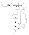
- a television receiver TVE - referred to in the English as a TV tuner - by means of an antenna A television signals, which it converts into the so-called color blanking sync signal, abbreviated composite signal.
- the composite signal often also referred to as CVBS signal after the English term Composite Video and Burst Synchronization, is supplied to the input of an analog-to-digital converter AD, whose output signal - the digitized CVBS signal - the input of a synchronizing pulse separator SIS and the first input of a comparator VL supplied at whose second input a reference variable RG is located.
- the output of the comparator VL is connected to the clock input of a counter Z1 whose reset input R is connected to the clock input T of a memory SP and the output of a controllable switch U and whose output is connected to the input of the memory SP.
- the line synchronization output of the synchronizing pulse separator SIS is connected to the input of a phase locked loop PLL whose output is connected to the first input of the controllable changeover switch U.
- the image synchronization output of the synchronizing pulse separator SIS is connected to the second input of the controllable changeover switch U.
- the analog-to-digital converter AD converts the analogue CVBS signal received by the television receiver TVE into a digital composite video signal.
- the comparator VL checks whether the pulses occurring in the FBAS signal exceed the predetermined reference value RG. If this is the case, the counter Z1 receives a count pulse. In this way, the glitches occurring in a line are counted whose amplitude and / or pulse width exceed the reference value RG.
- the counter Z1 is reset by the phase locked loop PLL with each horizontal synchronizing pulse, while the memory SP is clocked to take over the counter reading. In the memory SP, therefore, the measures of the lines can be stored.
- the controllable switch is switched to the other position B, then the counter Z1 is reset with each vertical synchronization pulse and the memory SP is clocked to take over the counter reading. In this case, the total dimensions for half or full images are stored in the memory SP.
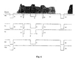
- the composite video signal contains, between the two horizontal synchronizing pulses H of one line, by way of example three narrow interfering pulses S1, S2 and S3 and a broad interfering pulse E which is an echo of a horizontal synchronizing pulse.
- the output of the comparator VL contains only the two horizontal sync pulses H, the glitches S1, S2 and E, because the glitch S3 is hidden because its amplitude does not exceed the reference size RG.
- the counter Z1 therefore only counts the falling edges of the glitches S1, S2 and E.
- the sync pulse separator generates in addition to the two horizontal sync pulses H and the interfering echo pulse E.
- the PLL is filtered out by the phase locked loop, because it passes only regularly recurring pulses or . generated.
- the phase locked loop replaces missing horizontal sync pulses.
- this requires a relatively narrow catch area.
- a counter or buffer Z2 and a processor P are provided instead of the counter Z1, a counter or buffer Z2 and a processor P.
- the output of the analog-to-digital converter AD is connected to the input of the first latch Z2 whose clock input is connected to the output of the comparator VL and whose output is connected to the input of the processor P.
- the output of the processor P is connected to the input of the summer SU, which may also be integrated in the processor P.
- the latch Z2 stores the amplitudes of the glitches S1, S2 and E by adding or integrating them or forwarding them one by one to the processor P, where the amplitudes of the glitches can be weighted by factors.
- the measures of the individual lines or half or full frames obtained from the amplitudes of the glitches are stored, depending on the position of the controllable switch U.
- the third exemplary embodiment of a circuit arrangement illustrated in FIG. 3 differs from the second exemplary embodiment shown in FIG. 2 in that the buffer Z2 is replaced by a counter Z3 and a clock generator CL.
- the output of the comparator VL is connected to the enable input of the counter or buffer Z3 whose clock input T is connected to the clock generator CL and whose output is connected to the input of the processor P.
- the latch Z3 stores the pulse widths of the glitches S1, S2 and E by adding them to a total pulse width, or individually to the processor P where they can be weighted with factors prior to addition.
- the memory SP obtained from the pulse widths of the glitches measures the individual lines or half or frames are stored, depending on the position of the controllable switch U.
- the construction is correct with respect to the antenna A, the television receiver TVE, the analog-to-digital converter AD, the comparator VL, the synchronizing pulse separator SIS, the phase locked loop PLL, the controllable changeover switch U, of the memory SP, the summer SU and the processor P with the circuit arrangements of Figures 2 and 3.
- the input of the processor P is connected to the output of a counter or latch Z4 whose input is connected to the output of a counter Z5 and whose clock input T is connected to the output of the comparator VL.
- the input of the counter Z5 is connected to the output of a clock generator CL; the reset input of the counter Z5, like the first input of the controllable switch U, is connected to the output of the phase-locked loop PLL.
- the latch Z4 takes over the count of the counter Z5 clocked by the clock generator CL, which corresponds to the respective position of the individual interference pulses S1, S2 and E.
- These counter readings representing the positions of the glitches are weighted in the processor P by factors; in the summer SU, the weighted values generated in this way are obtained Measured numbers added and - depending on the position of the controllable switch U - stored for lines, half or full frames.
- FIG. 5 fifth embodiment of a circuit arrangement is a combination of the first 4 shown in Figures 1-4 embodiments.
- the output of the counter Z1 and the outputs of the counters Z2, Z3 and Z4 are connected to the inputs of the processor P.
- the processor P weightes the items provided by the counter Z4 with factors and passes them to the summer SU for addition with the numerals provided by the counters Z1-Z3, where they are summed.
- the individual pulse widths and / or the amplitudes corresponding numerical measures of the counters Z2 and Z3 can also be weighted with factors before the addition.
- the processor P the sums of the unweighted amplitudes and / or pulse widths can be weighted with factors. But even the sums of the already weighted amplitudes and / or pulse widths can be weighted again with factors. Every conceivable combination of weighting is possible.
- the counters Z2 and Z3 can be designed as digital counters or, if the analog-to-digital converter AD is not provided, as an integrator.
- the summer SU and the memory SP may be integrated in the processor P.
- the invention is particularly well suited for diversity reception systems with multiple television receivers, because the invention provides a meaningful criterion for image quality.
- inventively generated measures and overall measures for the evaluation of the image quality of the individual built in a diversity reception system television receiver can be easily determine the television receiver with the best picture quality and select the reception.
- Switching to the television receiver with the best picture can be done line by line, half picture or frame by frame.
- the smallest total size television receiver produces the best picture while the one with the largest overall size provides the lowest quality picture.
- the invention for a mobile diversity reception system z.
- a mobile diversity reception system z.
- the invention is also suitable for television receivers and video recorders if an evaluation of the picture quality is required for some reason.
Landscapes
- Engineering & Computer Science (AREA)
- Signal Processing (AREA)
- Health & Medical Sciences (AREA)
- Biomedical Technology (AREA)
- General Health & Medical Sciences (AREA)
- Multimedia (AREA)
- Computer Networks & Wireless Communication (AREA)
- Radio Transmission System (AREA)
- Testing, Inspecting, Measuring Of Stereoscopic Televisions And Televisions (AREA)
- Picture Signal Circuits (AREA)
- Noise Elimination (AREA)
Claims (9)
- Dispositif de connexion pour déterminer la qualité d'une image de télévision, sachant que, dans une ligne après l'impulsion synchrone horizontale, des impulsions parasites sortantes sont détectées et sont évaluées en fonction de leurs paramètres afin d'obtenir une mesure de la qualité du signal vidéo, caractérisé en ce qu'un signal FBAS (FBAS) est acheminé vers l'entrée d'un séparateur d'impulsions synchrones (SIS) et vers la première entrée d'un comparateur (VL), une grandeur de référence (RG) étant appliquée à la deuxième entrée du comparateur, en ce que la sortie de synchronisation des lignes du séparateur d'impulsions synchrones (SIS) est reliée à l'entrée d'une boucle de déphasage (PLL), en ce que la sortie de la boucle de déphasage (PLL) ou la sortie de la synchronisation d'image du séparateur d'impulsions synchrones (SIS) est reliée à l'entrée de fréquence d'une unité de stockage (SP), en ce que la sortie du comparateur (VL) est reliée à l'entrée de déblocage d'un compteur (Z3) et à l'entrée de fréquence d'un additionneur analogique (SU), en ce que la sortie d'un générateur de fréquence (CL) est reliée à l'entrée de fréquence du compteur (Z3) pour compter ou intégrer les largeurs d'impulsion des impulsions parasites détectées et dont la sortie est reliée à l'entrée d'un processeur (P) et en ce que la sortie du processeur (P) est reliée à l'entrée de données de l'additionneur analogique (SU) dont la sortie est reliée à l'entrée de données de l'unité de stockage (SP).
- Dispositif de connexion selon la revendication 1, caractérisé en ce que la sortie de la boucle de déphasage (PLL) ou la sortie de la synchronisation d'image du séparateur d'impulsions synchrones (SIS) est reliée à l'entrée de réinitialisation d'un deuxième compteur (Z1) pour compter les impulsions parasites, dont l'entrée de fréquence est reliée à la sortie du comparateur (VL).
- Dispositif de connexion selon la revendication 1 ou 2, caractérisé en ce que la sortie de la boucle de déphasage (PLL) ou la sortie de la synchronisation d'image du séparateur d'impulsions synchrones (SIS) est reliée à l'entrée de réinitialisation d'un additionneur analogique (SU), en ce que le signal FBAS (FBAS) se trouve sur l'entrée d'une première unité de stockage intermédiaire (Z2) dont l'entrée de fréquence est reliée à la sortie du comparateur (VL) et dont la sortie est reliée à l'entrée d'un processeur (P).
- Dispositif de connexion selon la revendication 3, caractérisé en ce qu'une unité de stockage numérique ou un membre de balayage ou de maintien sert de première unité de stockage intermédiaire (Z2).
- Dispositif de connexion selon l'une des revendications 1 à 4, caractérisé en ce que les largeurs d'impulsion sont additionnées à l'aide du compteur numérique (Z3) ou sont intégrées à l'aide d'un intégrateur.
- Dispositif de connexion selon l'une des revendications 1 à 5, caractérisé en ce que la sortie du comparateur (VL) est reliée à l'entrée de fréquence d'une deuxième unité de stockage intermédiaire (Z4) et de l'additionneur analogique (SU), en ce que la sortie de la boucle de déphasage (PLL) est reliée à l'entrée de réinitialisation d'un troisième compteur (Z5), en ce que la sortie de la synchronisation d'image du séparateur d'impulsions synchrones (SIS) ou la sortie de la boucle de déphasage (PLL) est reliée à l'entrée de réinitialisation de l'additionneur analogique (SU), en ce que la sortie du générateur de fréquence (CL) est reliée à l'entrée de fréquence du troisième compteur (Z5) dont la sortie est reliée à l'entrée de la deuxième unité de stockage intermédiaire (Z4) et en ce que la sortie de la deuxième unité de stockage intermédiaire (Z4) est reliée à l'entrée du processeur (P).
- Dispositif de connexion selon l'une des revendications 1 à 6, caractérisé en ce que la sortie de la boucle de déphasage (PLL) est reliée à la première entrée et la sortie de la synchronisation d'image du séparateur d'impulsions synchrones (SIS) est reliée à la deuxième entrée d'un commutateur réglable (U) dont la sortie est reliée à l'entrée de fréquence de l'unité de stockage (SP) et à l'entrée de réinitialisation de l'additionneur analogique (SU).
- Dispositif de connexion selon l'une des revendications 1 à 7, caractérisé en ce qu'un convertisseur analogique-numérique (AD) est connecté en amont du comparateur (VL) et du séparateur d'impulsions synchrones (SIS).
- Dispositif de connexion selon l'une des revendications 1 à 8, caractérisé en ce que le signal FBAS (FBAS) est délivré par un récepteur de téléviseur (TVE).
Applications Claiming Priority (3)
| Application Number | Priority Date | Filing Date | Title |
|---|---|---|---|
| DE19743124A DE19743124B4 (de) | 1997-09-30 | 1997-09-30 | Verfahren zur Bestimmung der Qualität eines Videosignals und/oder eines Fernsehbildes |
| DE19743124 | 1997-09-30 | ||
| PCT/DE1998/002904 WO1999017557A1 (fr) | 1997-09-30 | 1998-09-30 | Procede pour determiner la qualite d'un signal video et/ou d'une image de television |
Publications (2)
| Publication Number | Publication Date |
|---|---|
| EP0941618A1 EP0941618A1 (fr) | 1999-09-15 |
| EP0941618B1 true EP0941618B1 (fr) | 2006-11-15 |
Family
ID=7844102
Family Applications (1)
| Application Number | Title | Priority Date | Filing Date |
|---|---|---|---|
| EP98955363A Expired - Lifetime EP0941618B1 (fr) | 1997-09-30 | 1998-09-30 | Dispositif pour determiner la qualite d'une image de television |
Country Status (6)
| Country | Link |
|---|---|
| US (1) | US6441847B1 (fr) |
| EP (1) | EP0941618B1 (fr) |
| JP (1) | JP3811818B2 (fr) |
| KR (1) | KR20000069200A (fr) |
| DE (2) | DE19743124B4 (fr) |
| WO (1) | WO1999017557A1 (fr) |
Families Citing this family (12)
| Publication number | Priority date | Publication date | Assignee | Title |
|---|---|---|---|---|
| DE19929071A1 (de) * | 1999-06-25 | 2000-12-28 | Fuba Automotive Gmbh | Antennendiversitysystem, insbesondere für den mobilen Fernsehempfang |
| DE10006701C2 (de) | 2000-02-16 | 2002-04-11 | Harman Becker Automotive Sys | Empfangseinrichtung |
| US6734898B2 (en) * | 2001-04-17 | 2004-05-11 | General Instrument Corporation | Methods and apparatus for the measurement of video quality |
| KR100927287B1 (ko) * | 2001-11-27 | 2009-11-18 | 소니 가부시끼 가이샤 | 안테나 레벨 표시 장치 및 방법, 및 수신 장치 |
| US20040207643A1 (en) * | 2003-04-18 | 2004-10-21 | Bozidar Janko | Attention model enhanced video waveform monitor |
| DE102004020503A1 (de) * | 2004-04-26 | 2005-11-17 | Fuba Automotive Gmbh & Co. Kg | Verfahren zum mobilen Empfang von Bildinformationen |
| DE102004058541B4 (de) * | 2004-12-03 | 2006-10-05 | Lear Corporation Gmbh & Co. Kg | Verfahren zur Rauschreduktion digitalisierter analoger Videosignale |
| JP4896661B2 (ja) * | 2006-10-26 | 2012-03-14 | オンセミコンダクター・トレーディング・リミテッド | クロック再生回路 |
| US9197934B2 (en) * | 2012-05-17 | 2015-11-24 | Stmicroelectronics, Inc. | Fault tolerant system with equivalence processing driving fault detection and backup activation |
| CN105681780B (zh) * | 2014-11-19 | 2018-06-15 | 深圳市中兴微电子技术有限公司 | 一种复合视频广播信号质量的测量方法和装置 |
| KR102510446B1 (ko) * | 2016-01-15 | 2023-03-15 | 삼성전자주식회사 | 외부 클락을 이용하여 비디오 동기 신호를 발생시키는 디스플레이 컨트롤러, 이를 포함하는 애플리케이션 프로세서, 및 이를 포함하는 전자 시스템 |
| US10085015B1 (en) * | 2017-02-14 | 2018-09-25 | Zpeg, Inc. | Method and system for measuring visual quality of a video sequence |
Citations (1)
| Publication number | Priority date | Publication date | Assignee | Title |
|---|---|---|---|---|
| US5303396A (en) * | 1990-06-13 | 1994-04-12 | Hitachi, Ltd. | Diversity reception having a plurality of antennas for use with moving vehicles |
Family Cites Families (36)
| Publication number | Priority date | Publication date | Assignee | Title |
|---|---|---|---|---|
| CH577765A5 (fr) * | 1972-12-05 | 1976-07-15 | Hartig Gunter | |
| US4268858A (en) * | 1977-03-04 | 1981-05-19 | Westinghouse Electric Corp. | TV Transmission system for long tow cables |
| DE3110890C2 (de) * | 1981-03-20 | 1983-04-14 | Philips Patentverwaltung Gmbh, 2000 Hamburg | Schaltungsanordnung für die Vertikalablenkung in einem Fernsehgerät |
| US4402013A (en) * | 1981-04-06 | 1983-08-30 | Rca Corporation | Video signal analyzer |
| EP0069791B1 (fr) * | 1981-07-11 | 1984-07-25 | Deutsche ITT Industries GmbH | Circuit intégré pour récepteurs de télévision comportant un circuit de séparation de signal de synchronisation et un circuit de réglage du niveau de verrouillage |
| US4471389A (en) * | 1982-03-01 | 1984-09-11 | Zenith Electronics Corporation | Interference pulse elimination in capacitance electronic disc systems |
| NL8302984A (nl) * | 1983-08-26 | 1985-03-18 | Philips Nv | Beeldweergeefinrichting met een ruisdetektor. |
| GB2148673B (en) * | 1983-10-24 | 1987-09-09 | Philips Electronic Associated | A signal quality detector for a teletext television receiver |
| DE3541306C1 (de) * | 1985-11-22 | 1986-08-28 | Philips Patentverwaltung Gmbh, 2000 Hamburg | Schaltungsanordnung fuer einen Videorecorder |
| US4682230A (en) * | 1986-03-21 | 1987-07-21 | Rca Corporation | Adaptive median filter system |
| JPS62272673A (ja) * | 1986-05-20 | 1987-11-26 | Sanyo Electric Co Ltd | ノイズリデユ−サ |
| DE3715929A1 (de) * | 1987-05-13 | 1988-11-24 | Thomson Brandt Gmbh | Schaltungsanordnung zur automatischen umschaltung der regelgeschwindigkeit eines phasenregelkreises |
| JPS63304728A (ja) * | 1987-06-05 | 1988-12-13 | Mitsubishi Electric Corp | 受信アンテナ切換/選択装置 |
| JPH02159886A (ja) * | 1988-12-13 | 1990-06-20 | Clarion Co Ltd | テレビジョンダイバシティ受信装置 |
| US4873574A (en) * | 1988-12-20 | 1989-10-10 | North American Philips Corporation | Noise measurement for video signals |
| DE3926336C2 (de) * | 1989-08-09 | 2001-03-29 | Heinz Lindenmeier | Antennendiversity-Empfangsanlage zur Elimination von Empfangsstörungen beim mobilen Empfang von Fernsehsignalen |
| US5025316A (en) * | 1989-11-06 | 1991-06-18 | North American Philips Corporation | Video noise reduction system with measured noise input |
| US5095310A (en) * | 1990-08-22 | 1992-03-10 | Storage Technology Corporation | Method and apparatus for using synthesized analog data for testing read circuitry in a magnetic tape data storage subsystem |
| GB2250395A (en) * | 1990-11-27 | 1992-06-03 | Ferguson Ltd | Reducing visibility of impulsive interference in television satellite recievers |
| US5335010A (en) * | 1991-02-08 | 1994-08-02 | U.S. Philips Corporation | Antenna diversity receiving system with antenna switching during line periods and signal quality evaluation during line blanking intervals |
| KR930001678A (ko) * | 1991-06-13 | 1993-01-16 | 강진구 | 영상 신호에 있어서의 잡음 검출 알고리즘 |
| DE4125460A1 (de) * | 1991-08-01 | 1993-02-04 | Philips Patentverwaltung | Verarbeitungseinheit fuer mindestens ein fernsehsignal |
| US5247350A (en) * | 1992-01-09 | 1993-09-21 | Meyer Corwyn R | Method and apparatus for testing video |
| DE4326390C2 (de) * | 1993-08-06 | 1999-05-12 | Philips Patentverwaltung | Verfahren zur Störsignalbefreiung von Videosignalen |
| DE69523113T2 (de) * | 1994-03-07 | 2002-06-06 | Koninklijke Philips Electronics N.V., Eindhoven | Rauschmessung |
| US5526061A (en) * | 1994-03-23 | 1996-06-11 | U.S. Philips Corporation | Circuit arrangement for demodulating a video signal |
| JP3254925B2 (ja) * | 1994-10-04 | 2002-02-12 | 松下電器産業株式会社 | 車載用tvダイバーシチ装置 |
| JP3307165B2 (ja) * | 1995-06-13 | 2002-07-24 | 松下電器産業株式会社 | 移動体用tvダイバーシチ装置 |
| US5777693A (en) * | 1994-10-04 | 1998-07-07 | Matsushita Electric Industrial Co., Ltd. | Diversity receiving apparatus for a mobile unit |
| JPH08149060A (ja) * | 1994-11-24 | 1996-06-07 | Matsushita Electric Ind Co Ltd | ダイバシティtv受信制御装置 |
| DE19518368C1 (de) * | 1995-05-22 | 1996-02-22 | Mb Video Gmbh | Verfahren und Vorrichtung zur Bewertung der Signalstärke eines mit einem Tuner empfangenen Fernsehsignals |
| US5818543A (en) * | 1995-09-06 | 1998-10-06 | Premier Wireless, Inc. | Diversity receiver for television |
| DE19541223A1 (de) * | 1995-11-04 | 1997-05-07 | Philips Patentverwaltung | Schaltungsanordnung zur Ableitung von horizontalfrequenten und vertikalfrequenten Impulsen |
| US5796777A (en) * | 1996-02-27 | 1998-08-18 | Motorola, Inc. | Apparatus and method for digitizing and detecting a received radio frequency signal |
| DE69614832T2 (de) * | 1996-05-24 | 2001-12-20 | Matsushita Electric Industrial Co., Ltd. | Verfahren und Schaltung zur Bestimmung eines Rauschwerts der repräsentativ ist für das Rauschen in einem Signal |
| DE19621206C2 (de) * | 1996-05-25 | 1999-07-08 | Grundig Ag | Verfahren zur störungsfreien Übertragung von Videosignalen über eine Funkübertragungsstrecke und Vorrichtung zur Durchführung des Verfahrens |
-
1997
- 1997-09-30 DE DE19743124A patent/DE19743124B4/de not_active Expired - Lifetime
-
1998
- 1998-09-30 JP JP51961799A patent/JP3811818B2/ja not_active Expired - Lifetime
- 1998-09-30 EP EP98955363A patent/EP0941618B1/fr not_active Expired - Lifetime
- 1998-09-30 US US09/319,087 patent/US6441847B1/en not_active Expired - Lifetime
- 1998-09-30 KR KR1019997004773A patent/KR20000069200A/ko not_active Withdrawn
- 1998-09-30 DE DE59813808T patent/DE59813808D1/de not_active Expired - Lifetime
- 1998-09-30 WO PCT/DE1998/002904 patent/WO1999017557A1/fr not_active Ceased
Patent Citations (1)
| Publication number | Priority date | Publication date | Assignee | Title |
|---|---|---|---|---|
| US5303396A (en) * | 1990-06-13 | 1994-04-12 | Hitachi, Ltd. | Diversity reception having a plurality of antennas for use with moving vehicles |
Also Published As
| Publication number | Publication date |
|---|---|
| JP2001511334A (ja) | 2001-08-07 |
| DE59813808D1 (de) | 2006-12-28 |
| WO1999017557A1 (fr) | 1999-04-08 |
| EP0941618A1 (fr) | 1999-09-15 |
| DE19743124A1 (de) | 1999-04-01 |
| JP3811818B2 (ja) | 2006-08-23 |
| KR20000069200A (ko) | 2000-11-25 |
| DE19743124B4 (de) | 2004-08-26 |
| US6441847B1 (en) | 2002-08-27 |
Similar Documents
| Publication | Publication Date | Title |
|---|---|---|
| DE69611702T2 (de) | Automatischer Bildabtastformatumwandler mit nahtloser Umschaltung | |
| DE3249724C2 (de) | System zur Erzeugung eines Bildes einer zeilenweise nach dem Zeilensprungverfahren abgetasteten Szene | |
| DE69027798T2 (de) | Ton- und Videozeitgebungssignale mit gleichzeitigen Markierungen | |
| DE69623851T2 (de) | Einrichtung zum Umwandeln des Abtastformats für ein Fernsehsystem mit hoher Auflösung | |
| DE69333361T2 (de) | Einrichtung zur Dekodierung von Daten in einer Austastlücke | |
| EP0941618B1 (fr) | Dispositif pour determiner la qualite d'une image de television | |
| DE3243673C2 (fr) | ||
| DE3625932A1 (de) | Bildwiedergabesystem mit fortlaufender abtastung | |
| DE69614832T2 (de) | Verfahren und Schaltung zur Bestimmung eines Rauschwerts der repräsentativ ist für das Rauschen in einem Signal | |
| DD237045A5 (de) | Fernsehempfaenger mit zeichengenerator | |
| DE69712291T2 (de) | Wiedergewinnung der horizontalen synchronisation | |
| DE68926230T2 (de) | Rauschmessung für Videosignale | |
| DE19752630B4 (de) | Verfahren für die automatische Bildgrößensteuerung halbbreiter Fernsehempfänger | |
| DE69421899T2 (de) | Vorrichtung und verfahren zur erzeugung periodischer synchronisationsreferenzen zur bildung eines synchronisationssignals | |
| EP0509390A1 (fr) | Méthode pour la transmission compatible d'une information supplémentaire indiquant le type de signal | |
| DE4127281A1 (de) | Schaltung fuer eine videoaufzeichnungs- und wiedergabeeinrichtung | |
| DE3782814T2 (de) | Verbesserungen bezueglich des fernsehens. | |
| DE19739898C2 (de) | Verfahren zum Mehrwegeempfang | |
| EP1188258B1 (fr) | Procede de reception mobile de signaux radio et circuit destine a mettre en oeuvre ledit procede | |
| DE60116502T2 (de) | Vorrichtung und verfahren zur erkennung der welligkeiten verursacht durch mehrwegeausbreitung und zur steuerung der empfangsantenne und des tuners | |
| DE69519275T2 (de) | Empfänger für fernsehsignale | |
| EP0370500A2 (fr) | Dispositif de circuit de sélection entre différentes méthodes de réduction du papillotement dans un récepteur de télévision | |
| EP1016278B1 (fr) | Intercalaire de separation pour la separation d'un signal transmis dans des intervalles de suppression d'un signal video et procede de redressement d'un tel signal | |
| EP0551314B1 (fr) | Systeme de transmission de television et decodeur pour un systeme de transmission de television | |
| EP0941617B1 (fr) | Procédé pour évaluer la qualité d'un signal de télévision |
Legal Events
| Date | Code | Title | Description |
|---|---|---|---|
| PUAI | Public reference made under article 153(3) epc to a published international application that has entered the european phase |
Free format text: ORIGINAL CODE: 0009012 |
|
| 17P | Request for examination filed |
Effective date: 19990527 |
|
| AK | Designated contracting states |
Kind code of ref document: A1 Designated state(s): DE FR GB IT |
|
| 17Q | First examination report despatched |
Effective date: 20040130 |
|
| GRAP | Despatch of communication of intention to grant a patent |
Free format text: ORIGINAL CODE: EPIDOSNIGR1 |
|
| RTI1 | Title (correction) |
Free format text: DEVICE FOR DETERMINING THE QUALITY OF A TELEVISION IMAGE SIGNAL |
|
| RIC1 | Information provided on ipc code assigned before grant |
Ipc: H04N 5/44 20060101ALI20060405BHEP Ipc: H04N 17/00 20060101AFI20060405BHEP |
|
| GRAS | Grant fee paid |
Free format text: ORIGINAL CODE: EPIDOSNIGR3 |
|
| GRAA | (expected) grant |
Free format text: ORIGINAL CODE: 0009210 |
|
| AK | Designated contracting states |
Kind code of ref document: B1 Designated state(s): DE FR GB IT |
|
| REG | Reference to a national code |
Ref country code: GB Ref legal event code: FG4D Free format text: NOT ENGLISH |
|
| REF | Corresponds to: |
Ref document number: 59813808 Country of ref document: DE Date of ref document: 20061228 Kind code of ref document: P |
|
| GBT | Gb: translation of ep patent filed (gb section 77(6)(a)/1977) |
Effective date: 20070214 |
|
| ET | Fr: translation filed | ||
| PLBE | No opposition filed within time limit |
Free format text: ORIGINAL CODE: 0009261 |
|
| STAA | Information on the status of an ep patent application or granted ep patent |
Free format text: STATUS: NO OPPOSITION FILED WITHIN TIME LIMIT |
|
| 26N | No opposition filed |
Effective date: 20070817 |
|
| REG | Reference to a national code |
Ref country code: FR Ref legal event code: PLFP Year of fee payment: 19 |
|
| REG | Reference to a national code |
Ref country code: FR Ref legal event code: PLFP Year of fee payment: 20 |
|
| PGFP | Annual fee paid to national office [announced via postgrant information from national office to epo] |
Ref country code: IT Payment date: 20170831 Year of fee payment: 20 Ref country code: DE Payment date: 20170821 Year of fee payment: 20 Ref country code: FR Payment date: 20170822 Year of fee payment: 20 Ref country code: GB Payment date: 20170821 Year of fee payment: 20 |
|
| REG | Reference to a national code |
Ref country code: DE Ref legal event code: R071 Ref document number: 59813808 Country of ref document: DE |
|
| REG | Reference to a national code |
Ref country code: GB Ref legal event code: PE20 Expiry date: 20180929 |
|
| PG25 | Lapsed in a contracting state [announced via postgrant information from national office to epo] |
Ref country code: GB Free format text: LAPSE BECAUSE OF EXPIRATION OF PROTECTION Effective date: 20180929 |