EP0941706B1 - Abdecktuch für ein Operationsmikroskop und Verfahren zum Betrieb und dessen Herstellung - Google Patents
Abdecktuch für ein Operationsmikroskop und Verfahren zum Betrieb und dessen Herstellung Download PDFInfo
- Publication number
- EP0941706B1 EP0941706B1 EP99104900A EP99104900A EP0941706B1 EP 0941706 B1 EP0941706 B1 EP 0941706B1 EP 99104900 A EP99104900 A EP 99104900A EP 99104900 A EP99104900 A EP 99104900A EP 0941706 B1 EP0941706 B1 EP 0941706B1
- Authority
- EP
- European Patent Office
- Prior art keywords
- sheet
- objective lens
- aperture
- seal
- lens barrel
- Prior art date
- Legal status (The legal status is an assumption and is not a legal conclusion. Google has not performed a legal analysis and makes no representation as to the accuracy of the status listed.)
- Expired - Lifetime
Links
- 238000000034 method Methods 0.000 title claims abstract description 28
- 238000004519 manufacturing process Methods 0.000 title claims abstract description 8
- 239000002245 particle Substances 0.000 claims description 8
- 230000008878 coupling Effects 0.000 claims 3
- 238000010168 coupling process Methods 0.000 claims 3
- 238000005859 coupling reaction Methods 0.000 claims 3
- 238000000151 deposition Methods 0.000 claims 1
- 239000000463 material Substances 0.000 description 8
- 239000012530 fluid Substances 0.000 description 6
- 239000000356 contaminant Substances 0.000 description 4
- 208000015181 infectious disease Diseases 0.000 description 4
- 239000011521 glass Substances 0.000 description 3
- 238000009434 installation Methods 0.000 description 3
- 238000001356 surgical procedure Methods 0.000 description 3
- 230000004888 barrier function Effects 0.000 description 2
- 238000010276 construction Methods 0.000 description 2
- 239000010453 quartz Substances 0.000 description 2
- VYPSYNLAJGMNEJ-UHFFFAOYSA-N silicon dioxide Inorganic materials O=[Si]=O VYPSYNLAJGMNEJ-UHFFFAOYSA-N 0.000 description 2
- 239000012780 transparent material Substances 0.000 description 2
- 241000191940 Staphylococcus Species 0.000 description 1
- 206010052428 Wound Diseases 0.000 description 1
- 238000004026 adhesive bonding Methods 0.000 description 1
- 230000004075 alteration Effects 0.000 description 1
- AZDRQVAHHNSJOQ-UHFFFAOYSA-N alumane Chemical group [AlH3] AZDRQVAHHNSJOQ-UHFFFAOYSA-N 0.000 description 1
- 210000003484 anatomy Anatomy 0.000 description 1
- 210000001367 artery Anatomy 0.000 description 1
- 239000008280 blood Substances 0.000 description 1
- 210000004369 blood Anatomy 0.000 description 1
- 210000001124 body fluid Anatomy 0.000 description 1
- 230000003749 cleanliness Effects 0.000 description 1
- 238000011109 contamination Methods 0.000 description 1
- 230000007812 deficiency Effects 0.000 description 1
- 239000004744 fabric Substances 0.000 description 1
- 208000006454 hepatitis Diseases 0.000 description 1
- 231100000283 hepatitis Toxicity 0.000 description 1
- 230000001926 lymphatic effect Effects 0.000 description 1
- 244000005700 microbiome Species 0.000 description 1
- 229920000642 polymer Polymers 0.000 description 1
- 230000001681 protective effect Effects 0.000 description 1
- 238000009958 sewing Methods 0.000 description 1
- 238000006467 substitution reaction Methods 0.000 description 1
- 210000003462 vein Anatomy 0.000 description 1
- 230000000007 visual effect Effects 0.000 description 1
Images


Classifications
-
- G—PHYSICS
- G02—OPTICS
- G02B—OPTICAL ELEMENTS, SYSTEMS OR APPARATUS
- G02B21/00—Microscopes
- G02B21/0004—Microscopes specially adapted for specific applications
- G02B21/0012—Surgical microscopes
-
- A—HUMAN NECESSITIES
- A61—MEDICAL OR VETERINARY SCIENCE; HYGIENE
- A61B—DIAGNOSIS; SURGERY; IDENTIFICATION
- A61B46/00—Surgical drapes
- A61B46/10—Surgical drapes specially adapted for instruments, e.g. microscopes
-
- Y—GENERAL TAGGING OF NEW TECHNOLOGICAL DEVELOPMENTS; GENERAL TAGGING OF CROSS-SECTIONAL TECHNOLOGIES SPANNING OVER SEVERAL SECTIONS OF THE IPC; TECHNICAL SUBJECTS COVERED BY FORMER USPC CROSS-REFERENCE ART COLLECTIONS [XRACs] AND DIGESTS
- Y10—TECHNICAL SUBJECTS COVERED BY FORMER USPC
- Y10S—TECHNICAL SUBJECTS COVERED BY FORMER USPC CROSS-REFERENCE ART COLLECTIONS [XRACs] AND DIGESTS
- Y10S359/00—Optical: systems and elements
- Y10S359/90—Methods
Definitions
- the present invention is directed, in general, to surgical drapes and, more specifically, to a surgical microscope operating drape and methods of draping a surgical microscope and manufacturing the drape.
- a surgical field as found in a typical hospital's operating room, is an environmentally controlled area where the risk of infection from naturally occurring organisms is minimized.
- the environment's "cleanliness" is controlled by limiting the introduction of infection-creating organisms and other contaminants by maintaining strict controls over the personnel and equipment that are present in the surgical field.
- the drapes are placed over the patient, operating room staff and/or equipment to form a sterile barrier, keeping any microorganisms and contaminants that could cause infections from migrating to exposed tissue and open wounds.
- the drapes prevent the bodily fluids, such as blood or lymphatic fluids, which are encountered during most surgical procedures from settling on the operating room's furniture and equipment.
- These fluids may become airborne when, for instance, a vein or artery is severed.
- these fluids themselves may contain contaminants, such as hepatitis or staphylococcus, which can be transmitted to the other persons in the room.
- these fluids may also settle on furniture or equipment of the room, which then become contaminated and a hazard to those persons who must work in the room. Instead, the airborne fluids will ultimately settle on the drapes and not on the draped furniture and equipment.
- the surgical microscope is typically a ceiling-mounted device that may be raised or lowered and positioned over any part of the patient's body.
- the surgical microscope often has multiple eyepieces that permit the surgeon and others to simultaneously view the magnified area under the microscope's objective lens.
- a microscope drape used to create a sterile barrier, is typically affixed to the microscope at the lens housing of the objective lens, to orient the drape with respect to the remaining structure of the microscope. Once the microscope drape is attached to the objective lens barrel, other portions of the drape may be spread and positioned to cover the remainder of the microscope structure.
- the objective lens barrels for comparable surgical microscopes of different manufacturers are often of different sizes.
- a microscope drape that fits the objective lens barrel of one microscope may not fit the objective lens barrel of a similar microscope made by a different manufacturer. Consequently, a larger and more expensive inventory of several different drapes is necessary to accommodate the different microscope objective lens barrels.
- several surgical microscopes have objective lens barrels that are close in size. Therefore, if an incorrect drape is accidentally used and the fit is not secure, sudden slippage of the mounting device, such as a mounting ring, into the surgical field could occur during an operation, possibly resulting in serious complications to the patient.
- US-A-3 528 720 discloses a microscope enveloping sheet with an elastomeric dilatable annular body receiving the lens frame of the microscope.
- US-A-5 682 264 discloses a microscope drape with a flexible and deformable conical positioning member for a lens unit.
- a rigid ring preferable of aluminium forms a loose adapter.
- a drape includes: (1) a sheet, having a sheet aperture therethrough, that covers at least a portion of the surgical microscope, (2) a rigid, planar seal mount, coupled to the sheet and having a mount aperture therethrough that aligns with the sheet aperture and (3) an elastomeric sheet seal, coupled to the planar seal mount and having a dilatable seal aperture therethrough that has a constricted radius less than the mount aperture, aligns with the mount aperture, expands to receive the objective lens barrel therethrough and elastically constricts about the objective lens barrel.
- the present invention therefore introduces a surgical microscope operating drape having features that allow the sheet to be more flexible in the types of microscopes that it can accommodate.
- sheet is defined broadly to include not only sheets in planar form, but also in cylindrical or tubular form (irrespective of whether the ends of the cylinder or tube are open or closed).
- Sheet is further defined to include extrudable materials (such as plastic) as well as woven materials (such as cloth).
- the rigid, planar seal mount may extend sufficiently to provide handles (perhaps with handle apertures) for fitting the drape to, and removing the drape from, the microscope.
- the drape further comprises a transparent objective lens cover, separate from the sheet and having a flexible barrel adapter, the flexible barrel adapter expandable to fit about and cover the objective lens barrel, the sheet and the objective lens cover cooperating to cover the portion of the surgical microscope, including the objective lens barrel. Because they are wholly separate, relatively few sheets and objective lens covers may be combined to fit a wide range of microscopes, thereby avoiding the significant expense of the prior art drapes discussed above.
- the present invention can employ an objective lens cover (perhaps without a flexible barrel adapter) that is coupled to the planar seal mount, yielding a unitary microscope drape.
- the elastomeric sheet seal advantageously provides sufficient frictional contact with the barrel of the microscope's objective lens to hold the objective lens cover in place.
- the objective lens aperture has an elastic band thereabout to render the objective lens cover elastically deformable.
- the elastic band is bonded (perhaps by gluing or sewing) to the sheet and extends entirely about the objective lens aperture. This need not be the case, however.
- the dilatable seal lens aperture forms a particle-resistant seal about the objective lens barrel.
- a particle-resistant seal while advantageously protecting the microscope against contamination, is not necessary to the present invention.
- the objective lens cover is composed in part of plastic.
- the objective lens cover may be composed of another transparent material, such as glass or quartz.
- the flexible barrel adapter comprises a resilient gasket.
- the resilient gasket expands to the extent necessary to allow the objective lens barrel to be inserted into the objective lens cover.
- the flexible barrel adapter fits over the sheet proximate the objective lens aperture.
- the flexible barrel adapter may simply abut the sheet or allow a portion of the objective lens barrel to be exposed.
- the drape further comprises at least one hook-and-pile fastener (commonly known as VELCRO®, manufactured by the Dupont Corporation), coupled to the sheet, that fixes the sheet to a portion of the surgical microscope.
- hook-and-pile fastener commonly known as VELCRO®, manufactured by the Dupont Corporation
- the surgical operating microscope generally designated 100, has a main body 110 with a plurality of eyepieces (one of which is designated 120) extending upwardly from the main body 110. Also shown is an objective lens 130 coupled to an objective lens barrel 140.
- the objective lens barrel 140 projects downwardly from the main body 110 such that, when the microscope 100 is placed over the patient's body, the objective lens 130 points down toward the body.
- the eyepieces 120 provide the surgeon and/or other surgical team members precise visual control of the region of the patient undergoing an operation through the objective lens 130.
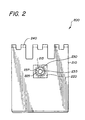
- FIGURE 2 illustrated is a plan view of one embodiment of a microscope drape constructed according to the principles of the present invention.
- the microscope drape generally designated 200, comprises a sheet 210, a planar seal mount 220, an elastomeric sheet seal 230, and a plurality of fasteners (one of which is designated 240).
- the sheet 210 is formed as a tube having a single closed end, that has a sheet aperture 215 opening through the sheet 210.
- a plurality of fasteners 240 are shown attached to both ends of the sheet 210.
- the sheet 210 (again, preferably in the form of a tube) has dimensions that allow the sheet 210 substantially to cover the surgical operating microscope main body 110.
- surgical operating microscopes 100 vary in size and dimensions and that the dimensions of the sheet 210 are selected to accommodate the largest microscope 100 dimensions in use.
- the materials that may be used for the sheet 210 are typically those materials that are suitable for use in an operating room environment, e.g ., a heat-resistant polymer.
- the planar seal mount 220 is attached (coupled in some manner) to the sheet 210 and located proximate the sheet aperture 215.
- the planar seal mount 220 comprises a mount aperture 225 which is aligned with the sheet aperture 215.
- the planar seal mount 220 is roughly square in shape, however, one skilled in the art will recognize that circular, rectangular or other shapes may be desirable and are within the scope of the present invention.
- the planar seal mount 220 may advantageously be elongated.
- the dilatable seal aperture 235 is constructed with a constricted diameter 237 less than the diameter of the smallest objective lens barrel 140 of commercial operating microscopes 100.
- the dilatable seal aperture 235 allows the sheet aperture 215 to accommodate objective lens barrels 140 of varying diameters from the smallest diameter objective lens barrel 140 to the largest diameter objective lens barrel 140 that is commonly in use.
- the diameter 237 is slightly smaller than the smallest diameter objective lens barrel 140.
- the seal 230 closes securely about the lens barrel 140.
- the elastomeric sheet seal 230 forms a particle-resistant seal when stretched over the objective lens barrel 140.
- the particle-resistant seal prevents particles or droplets from passing between the elastomeric sheet seal 230 and the objective lens barrel 140 and contaminating the main body 110 of the microscope 100.
- the sheet 210 is dressed onto the microscope 100 by lifting the rigid seal mount 220 around the objective lens barrel 140.
- the elastomeric sheet seal 230 deforms about the objective lens barrel 140 to form a seal.
- the sheet 210 is then wrapped about the microscope body 110 leaving the eyepieces 120 exposed and the sheet 210 is secured with fasteners 240.
- the fasteners 240 in the illustrated embodiment are hook-and-pile fasteners (widely known as VELCRO®, one brand name under which such fasteners are commercially available), however, other fastening methods and devices are well known in the art, such as ties or safety pins.
- the sheet 210 may be stored within a toroidal bag (not shown) attached to the planar seal mount 220. Once the objective lens barrel 140 is inserted through the dilatable seal aperture 235, the toroidal bag can be opened, freeing the sheet 210 and allowing the sheet 210 to be unfurled about and cover the surgical operating microscope main body 110.
- a toroidal bag (not shown) attached to the planar seal mount 220.
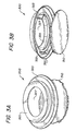
- FIGURE 3A and 3B illustrated are upper and lower exploded isometric views of one embodiment of a microscope objective lens cover for use with the microscope drape of FIGURE 2.
- the microscope objective lens cover 300 comprises a transparent objective lens cover 310, and a flexible barrel adaptor 320 that combine to provide a protective cover for the objective lens 130 from fluids and contaminants usually encountered during a surgical procedure.
- the flexible barrel adaptor 320 includes a resilient gasket 325 formed radially about a barrel adaptor aperture 327.
- the lens cover 310 may be composed of plastic or any other transparent material, such as glass or quartz.
- the barrel adaptor 320 may be composed of plastic or any other suitable material, and need not be transparent.
- the lens cover 310 and barrel adaptor 320 may be composed of a combination of materials, such as glass and plastic, respectively.
- the resilient gasket 325 is sized so that the gasket 325 expands and firmly contacts the lens barrel 140 when the flexible barrel adaptor 320 is pressed onto the lens barrel 140, thus holding the barrel adaptor 320 in place.
- the barrel adaptor 320 further comprises a plurality of lens supports 323 which hold the transparent objective lens cover 310 in place.
- the flexible barrel adapter 320 may simply abut the sheet 210 or allow a portion of the objective lens barrel 140 to be exposed.
- the flexible barrel adaptor 320 may be permanently affixed to the planar seal mount 220, so that the entire assembly may be installed in a single motion over the objective lens barrel 140.
- FIGURE 4A and 4B illustrated are exploded isometric views of one embodiment of a small lens adaptor for use with the objective lens cover of FIGURES 3A and 3B.
- the small lens adaptor 450 comprises an adaptor body 451 and a small lens resilient gasket 455 formed radially about a small lens barrel adaptor aperture 427.
- the adaptor body 451 and gasket 455 are formed of the same materials as the flexible barrel adaptor 320 and resilient gasket 325 of FIGUREs 3A and 3B.
- the small lens resilient gasket 455 functions for smaller diameter lenses in an manner analogous to the resilient gasket 325 of FIGURES 3A and 3B.
- the adaptor body 451 is constructed so that a plurality of adaptor clips 453 engage securely with a friction fit about the outer surface 423 of the flexible barrel adaptor 320.
- This embodiment enables the barrel adaptor 320 to fit smaller diameter lenses than it could otherwise accommodate.
- the lens diameter ranges for the barrel adaptor 320 and the small lens barrel adaptor 450 overlap slightly, e.g. , a barrel adaptor 320 range from 50 to 76 mm (2" to 3") with a small lens barrel adaptor 350 range from 38 to 54 mm (1.5" to 2.125").
- a barrel adaptor 320 range from 50 to 76 mm (2" to 3"
- a small lens barrel adaptor 350 range from 38 to 54 mm (1.5" to 2.125").
- the sizes specified are not limiting to the scope of the present invention, but are provided solely for illustrative purposes.
- FIGURES 5A, 5B and 5C illustrated are sectional views of one embodiment of the microscope drape and objective lens cover of FIGURE 4 along the plane 5-5 installed on three different size objective lenses.
- the resilient gasket 325 of the flexible barrel adaptor 320 flexibly engages the objective lens barrel 140.
- the planar seal mount 220 and flexible barrel adaptor 320 are both mechanically bonded to the sheet 210 so that the assembly may be installed in a single motion.
- FIGURE 5A illustrates installation of the microscope drape over a lens at the maximum capacity of the flexible barrel adaptor 320.
- FIGURE 5B illustrates installation of the microscope drape over a lens at the minimum capacity of the flexible barrel adaptor 320.
- FIGURE 5C illustrates installation of the microscope drape over a lens employing the small lens adaptor 450 of FIGURES 4A and 4B.
- a drape includes: (1) a sheet, having a sheet aperture therethrough, that covers at least a portion of the surgical microscope, (2) a rigid, planar seal mount, coupled to the sheet and having a mount aperture therethrough that aligns with the sheet aperture and (3) an elastomeric sheet seal, coupled to the planar seal mount and having a dilatable seal aperture therethrough that has a constricted radius less than the mount aperture, aligns with the mount aperture, expands to receive the objective lens barrel therethrough and elastically constricts about the objective lens barrel.
Landscapes
- Health & Medical Sciences (AREA)
- Surgery (AREA)
- Physics & Mathematics (AREA)
- General Health & Medical Sciences (AREA)
- Life Sciences & Earth Sciences (AREA)
- Analytical Chemistry (AREA)
- Medical Informatics (AREA)
- Optics & Photonics (AREA)
- Chemical & Material Sciences (AREA)
- Engineering & Computer Science (AREA)
- Biomedical Technology (AREA)
- Heart & Thoracic Surgery (AREA)
- General Physics & Mathematics (AREA)
- Molecular Biology (AREA)
- Animal Behavior & Ethology (AREA)
- Public Health (AREA)
- Veterinary Medicine (AREA)
- Microscoopes, Condenser (AREA)
- Materials For Medical Uses (AREA)
Claims (21)
- Abdeckung (200) für ein OP-Mikroskop (100), von dem ein Objektivtubus (140) absteht, und die aufweist:ein Blatt (210) mit einer Öffnung (215), mit dem mindestens einen Teil des OP-Mikroskops (100) abdeckbar ist,einen starren planaren Dichtungshalter (220), der mit dem Blatt (210) verbunden ist und eine Halterungsöffnung (225) enthält, die mit der Blattöffnung (215) ausgerichtet ist,sowie weiterhineine elastomere Blattdichtung (230), die mit dem planaren Dichtungshalter (220) verbunden ist und eine aufweitbare Dichtungsöffnung (235) enthält, deren Durchmesser im zusammengezogenen Zustand kleiner als der der Halterungsöffnung (225) ist, die weiterhin mit der Halterungsöffnung (225) ausgerichtet ist, die den Objektivtubus (140) aufnehmen und die sich um den Objektivtubus (140) elastisch zusammenziehen kann.
- Abdeckung nach Anspruch 1, weiterhin mit einer von dem Blatt (210) getrennten transparenten Objektivabdeckung (310) mit einem flexiblen Tubusadapter (320), der aufweitbar ist, um sich auf den Objektivtubus (140) aufsetzen zu lassen und ihn zu bedecken, wobei das Blatt (210) und die Objektivabdeckung (310) im Zusammenwirken den Teil des OP-Mikroskops einschl. des Objektivtubus (140) abdecken.
- Abdeckung nach Anspruch 1, bei dem die elastomere Blattdichtung (230) einen gegen Teilchen resistenten dichten Abschluss um den Objektivtubus (140) bildet.
- Abdeckung nach Anspruch 2, deren Objektivabdeckung (310) sich teilweise aus Kunststoff zusammensetzt.
- Abdeckung nach Anspruch 2, deren flexibler Tubusadapter (320) eine federelastische Dichtung (325) aufweist.
- Abdeckung nach Anspruch 2, deren flexibler Tubusadapter (320) nahe der Dichtungsöffnung (215) auf das Blatt (210) passt.
- Abdeckung nach Anspruch 1 weiterhin mit mindestens einem Klettverschlusselement (240), das mit dem Blatt (210) verbunden ist und das Blatt (210) auf dem besagten Teil des OP-Mikroskops (100) festlegt.
- Verfahren zum Abdecken eines OP-Mikroskops (100), von dem ein Objektivtubus (140) absteht, mit folgenden Schritten:gekennzeichnet durch folgenden weiteren Schritt:Abdecken mindestens eines Teils des OP-Mikropskops mit einem Blatt (210), das mindestens eine Öffnung (215) enthält und mit einem starren ebenflächigen Dichtungshalter (220) verbunden ist, der eine Halterungsöffnung (225) enthält, die mit der Öffnung (215) im Blatt ausgerichtet ist,Einsetzen des Objektivtubus (140) durch eine aufweitbare Dichtungsöffnung (235) in einer elastomeren Blattdichtung (230), die mit dem ebenflächigen Dichtungshalter (220) verbunden ist, wobei die aufweitbare Dichtungsöffnung (235) im eingezogenen Zustand einen kleineren Durchmesser als den der Halterungsöffnung (225) hat, mit der Halterungsöffnung (225) ausgerichtet ist, sich zur Aufnahme des Objektivtubus (140) aufweitet und sich elastisch um den Objektivtubus (140) zusammenzieht.
- Verfahren nach Anspruch 8,weiterhin mit dem Schritt des Abdeckens des Objektivtubus (140) mit einer transparenten Objektivabdeckung (310), die getrennt vom Blatt (210) vorliegt und einen flexiblen Tubusadapter (320) aufweist, der aufweitbar ist, um sich um den Objektivtubus (140) zu legen, wobei das Blatt (210) und die Objektivabdeckung (310) im Zusammenwirken den besagten Teil des OP-Mikroskops (100) einschl. des Objektivtubus (140) abdecken.
- Verfahren nach Anspruch 8, weiterhin mit dem Schritt des Ausbildens eines gegen Teilchen resistenten Abschlusses (230) um den Objektivtubus (140).
- Verfahren nach Anspruch 9, bei dem die Objektivabdeckung (310) sich teilweise aus Kunststoff zusammensetzt.
- Verfahren nach Anspruch 9, bei dem der flexible Tubusadapter (320) eine federelastische Dichtung (325) aufweist.
- Verfahren nach Anspruch 9, bei dem man im Schritt des Abdeckens des Objektivtubus (140) den flexiblen Tubusadapter (320) nahe der aufweitbaren Dichtungsöffnung (215) auf das Blatt (210) aufsetzt.
- Verfahren nach Anspruch 8,weiterhin mit dem Schritt des Aufsetzens des Blatts (210) auf den besagten Teil des OP-Mikroskops (100) mittels mindestens eines Klettverschlusselements (240), das mit dem Blatt (210) verbunden ist.
- Verfahren zum Herstellen einer Abdeckung (200) für ein OP-Mikroskop (100), von dem ein Objektivtubus (140) absteht, mit folgenden Schritten:gekennzeichnet weiterhin durch folgenden Schritt:Erzeugen einer Blattöffnung (215) in einem Blatt (210), mit dem mindestens ein Teil des OP-Mikroskops (100) abdeckbar ist,Verbinden eines starren ebenflächigen Dichtungshalters (220) mit dem Blatt (210), wobei der ebenflächige Dichtungshalter (220) eine Halterungsöffnung (225) enthält, die mit der Blattöffnung (215) ausgerichtet ist,Verbinden einer elastomeren Blattdichtung (230) mit dem ebenflächigen Dichtungshalter (220), wobei die Blattdichtung (230) eine aufweitbare Dichtungsöffnung (235) enthält, deren Durchmesser im eingezogenen Zustand kleiner ist als der der Halterungsöffnung (225), die mit der Halterungsöffnung (225) ausgerichtet ist, sich zur Aufnahme des Objektivtubus (140) aufweitet und sich elastisch um den Objektivtubus (140) zusammenzieht.
- Verfahren nach Anspruch 15, weiterhin mit dem Schritt des Herstellens einer vom Blatt (210) getrennten transparenten Objektivabdeckung (310) mit einem flexiblen Tubusadapter (320), der aufweitbar ist, um sich um den Objektivtubus (140) zu legen und ihn abzudecken, wobei das Blatt (210) und die Objektivabdeckung (310) im Zusammenwirken den besagten Teil des OP-Mikroskops (100) mit dem Objektivtubus (140) abdeckt.
- Verfahren nach Anspruch 15, bei dem die aufweitbare Dichtungsöffnung (235) so bemessen ist, dass sie einen für Teilchen resistenten Verschluss um den Objektivtubus (140) bildet.
- Verfahren nach Anspruch 16, bei dem man im Herstellschritt die Objektivabdeckung (310) teilweise aus Kunststoff fertigt.
- Verfahren nach Anspruch 16, bei dem man im Herstellschritt nahe dem flexiblen Tubusadapter (320) eine federelastische Dichtung (325) aufbringt.
- Verfahren nach Anspruch 16, bei dem der flexible Tubusadapter (320) so bemessen ist, dass er nahe der aufweitbaren Dichtungsöffnung (235) auf das Blatt (210) aufsetzbar ist.
- Verfahren nach Anspruch 15, bei dem man weiterhin mindestens ein Klettverschlusselement (240) mit dem Blatt (210) verbindet, wobei mit dem mindestens einen Klettverschlusselement (240) das Blatt (210) auf dem besagten Teil des OP-Mikroskops (140) festlegbar ist.
Applications Claiming Priority (2)
| Application Number | Priority Date | Filing Date | Title |
|---|---|---|---|
| US42062 | 1998-03-13 | ||
| US09/042,062 US6116741A (en) | 1998-03-13 | 1998-03-13 | Surgical microscope operating drape and methods of operation and manufacture thereof |
Publications (2)
| Publication Number | Publication Date |
|---|---|
| EP0941706A1 EP0941706A1 (de) | 1999-09-15 |
| EP0941706B1 true EP0941706B1 (de) | 2003-07-02 |
Family
ID=21919844
Family Applications (1)
| Application Number | Title | Priority Date | Filing Date |
|---|---|---|---|
| EP99104900A Expired - Lifetime EP0941706B1 (de) | 1998-03-13 | 1999-03-11 | Abdecktuch für ein Operationsmikroskop und Verfahren zum Betrieb und dessen Herstellung |
Country Status (4)
| Country | Link |
|---|---|
| US (1) | US6116741A (de) |
| EP (1) | EP0941706B1 (de) |
| AT (1) | ATE243983T1 (de) |
| DE (1) | DE69909155T2 (de) |
Families Citing this family (25)
| Publication number | Priority date | Publication date | Assignee | Title |
|---|---|---|---|---|
| EP1265522A1 (de) * | 2000-03-23 | 2002-12-18 | Atropos Limited | Einführvorrichtung für ein endoskop |
| WO2004019107A1 (de) * | 2002-08-16 | 2004-03-04 | Stuemed Gmbh | Steriler mikroskopüberzug mit objektivadapter |
| DE10250811A1 (de) * | 2002-08-16 | 2004-03-04 | Stuemed Gmbh | Mikroskopbezug mit Objektivring II |
| DE10311198B4 (de) * | 2003-02-06 | 2016-09-22 | Carl Zeiss Meditec Ag | Haltevorrichtung mit durchsichtigem Abdeckelement für Drape sowie Drape für ein Operationsmikroskop mit einer solchen Haltevorrichtung |
| US6869194B2 (en) * | 2003-03-24 | 2005-03-22 | Contour Fabricators, Inc. | Sterilizable drape for ophthalmoscopic lens |
| US6902278B2 (en) * | 2003-03-24 | 2005-06-07 | Andrew J. Bala | Surgical microscope drape assembly |
| US7232230B2 (en) * | 2003-03-24 | 2007-06-19 | Bala Andrew J | Surgical microscope drape with removable lens assembly |
| US7234824B2 (en) * | 2003-09-22 | 2007-06-26 | Langley Nicholas M | Glare-elimination device for surgical microscopes |
| US6876503B1 (en) | 2003-10-28 | 2005-04-05 | Contour Fabricators, Inc. | Microscope drape lens protective cover assembly |
| US20050094269A1 (en) * | 2003-10-31 | 2005-05-05 | Moses Gary L. | Microscope drape coupling system and method |
| US20080144178A1 (en) * | 2006-12-13 | 2008-06-19 | Microtek Medical, Inc. | Microscope drape lens cover system and assembly method |
| US20100238551A1 (en) * | 2009-03-19 | 2010-09-23 | Hubbs Charles M | Surgical microscope drape lens for reducing glare |
| US8506094B2 (en) | 2009-12-29 | 2013-08-13 | Medline Industries, Inc. | Medical lens assemblies and sterile drapes with a lens assembly |
| CA2817437C (en) * | 2010-11-19 | 2018-05-22 | Leopold Lackner | A cover for an ultrasonic transducer |
| US8910637B2 (en) * | 2012-12-12 | 2014-12-16 | Marilyn Winer | Sterile drape for robotic surgical equipment |
| EP3164021B1 (de) * | 2014-07-01 | 2019-09-11 | Spier, Laurence | Abschirmung für chirurgisches roboterinstrument |
| USD877226S1 (en) | 2017-04-28 | 2020-03-03 | Ecolab Usa Inc. | Optical lens housing |
| USD875151S1 (en) | 2017-04-28 | 2020-02-11 | Ecolab Usa Inc. | Microscope drape |
| WO2018217430A1 (en) | 2017-05-25 | 2018-11-29 | Covidien Lp | Robotic surgical systems and drapes for covering components of robotic surgical systems |
| EP3716882A4 (de) | 2017-12-01 | 2021-08-25 | Covidien LP | Abdecktuchverwaltungsanordnungen für robotische chirurgische systeme |
| DE102018107357A1 (de) * | 2018-03-28 | 2019-10-02 | Aesculap Ag | Montageadapter zur Befestigung eines Sterilüberzugs an einem Mikroskop, Mikroskop zur Verwendung mit einem derartigen Adapter sowie System mit einem deratigen Mikroskop und einem derartigen Adapter |
| WO2020006243A1 (en) * | 2018-06-27 | 2020-01-02 | Stryker Corporation | A protective apparel system with a lens assembly |
| US12070361B2 (en) | 2020-05-08 | 2024-08-27 | Micah Nuzum | Protective shield for surgical microscope |
| DE102020131496A1 (de) * | 2020-11-27 | 2022-06-02 | Carl Zeiss Meditec Ag | Halteelement für ein Drape für ein Operationsmikroskop |
| EP4475783A4 (de) * | 2022-02-07 | 2025-10-15 | Mazor Robotics Ltd | Gehäuse für einen sterilen deckel und filter |
Citations (1)
| Publication number | Priority date | Publication date | Assignee | Title |
|---|---|---|---|---|
| US3528720A (en) * | 1968-12-18 | 1970-09-15 | Richards Mfg Co | Operating microscope envelope means |
Family Cites Families (11)
| Publication number | Priority date | Publication date | Assignee | Title |
|---|---|---|---|---|
| US3698791A (en) * | 1971-04-19 | 1972-10-17 | Xerox Corp | Drape for operating microscope |
| US3796477A (en) * | 1972-09-25 | 1974-03-12 | Xomox Corp | Lens housing and lens cover for objective lens ring of an operating microscope |
| US4176701A (en) * | 1978-09-28 | 1979-12-04 | Welgan Peter R | Camera rain shield |
| US4266663A (en) * | 1979-11-13 | 1981-05-12 | Carl Zeiss, Inc. | Surgical drape for an operating microscope |
| US4385812A (en) * | 1981-02-02 | 1983-05-31 | Surgikos, Inc. | Objective lens cover assembly for an operating microscope |
| US4799779A (en) * | 1988-03-22 | 1989-01-24 | Mesmer Jeffrey C | Microscope drape |
| US5155624A (en) * | 1990-06-25 | 1992-10-13 | Smith & Nephew Richards, Inc. | Lens housing for sterile cover of an operating microscope |
| US5311358A (en) * | 1992-10-08 | 1994-05-10 | Time Surgical, Inc. | Universal microscope drape |
| US5682264A (en) * | 1993-03-01 | 1997-10-28 | Microtek Medical, Inc. | Universal microscope drape |
| US5467223A (en) * | 1993-12-16 | 1995-11-14 | Xomed-Treace Inc. | Drape adapter |
| US5853363A (en) * | 1997-07-28 | 1998-12-29 | Deka Medical, Inc. | Surgical microscope operating drape and methods of operation and manufacture thereof |
-
1998
- 1998-03-13 US US09/042,062 patent/US6116741A/en not_active Expired - Lifetime
-
1999
- 1999-03-11 DE DE69909155T patent/DE69909155T2/de not_active Expired - Fee Related
- 1999-03-11 EP EP99104900A patent/EP0941706B1/de not_active Expired - Lifetime
- 1999-03-11 AT AT99104900T patent/ATE243983T1/de not_active IP Right Cessation
Patent Citations (1)
| Publication number | Priority date | Publication date | Assignee | Title |
|---|---|---|---|---|
| US3528720A (en) * | 1968-12-18 | 1970-09-15 | Richards Mfg Co | Operating microscope envelope means |
Also Published As
| Publication number | Publication date |
|---|---|
| DE69909155D1 (de) | 2003-08-07 |
| US6116741A (en) | 2000-09-12 |
| ATE243983T1 (de) | 2003-07-15 |
| DE69909155T2 (de) | 2004-01-08 |
| EP0941706A1 (de) | 1999-09-15 |
Similar Documents
| Publication | Publication Date | Title |
|---|---|---|
| EP0941706B1 (de) | Abdecktuch für ein Operationsmikroskop und Verfahren zum Betrieb und dessen Herstellung | |
| US5853363A (en) | Surgical microscope operating drape and methods of operation and manufacture thereof | |
| EP3029506B1 (de) | Medizinische linsenanordnungen und sterile abdecktücher mit einer linsenanordnung | |
| KR101436664B1 (ko) | 현미경 드레이프 렌즈 커버 시스템 및 조립 방법 | |
| US5274500A (en) | Video camera drape with lens | |
| AU653296B2 (en) | Universal microscope drape | |
| US6318864B1 (en) | Sterile instruments cover for use on surgical microscopes | |
| US20050094269A1 (en) | Microscope drape coupling system and method | |
| US6024454A (en) | Microscope drape system | |
| US11925430B2 (en) | Preloaded sterile bag | |
| US20180116745A1 (en) | Microscope drape for sterile environments |
Legal Events
| Date | Code | Title | Description |
|---|---|---|---|
| PUAI | Public reference made under article 153(3) epc to a published international application that has entered the european phase |
Free format text: ORIGINAL CODE: 0009012 |
|
| AK | Designated contracting states |
Kind code of ref document: A1 Designated state(s): AT BE CH CY DE DK ES FI FR GB GR IE IT LI LU MC NL PT SE |
|
| AX | Request for extension of the european patent |
Free format text: AL;LT;LV;MK;RO;SI |
|
| 17P | Request for examination filed |
Effective date: 20000313 |
|
| AKX | Designation fees paid |
Free format text: AT BE CH CY DE DK ES FI FR GB GR IE IT LI LU MC NL PT SE |
|
| AXX | Extension fees paid |
Free format text: AL PAYMENT 20000313;LT PAYMENT 20000313;LV PAYMENT 20000313;MK PAYMENT 20000313;RO PAYMENT 20000313;SI PAYMENT 20000313 |
|
| GRAH | Despatch of communication of intention to grant a patent |
Free format text: ORIGINAL CODE: EPIDOS IGRA |
|
| GRAH | Despatch of communication of intention to grant a patent |
Free format text: ORIGINAL CODE: EPIDOS IGRA |
|
| GRAA | (expected) grant |
Free format text: ORIGINAL CODE: 0009210 |
|
| AK | Designated contracting states |
Designated state(s): AT BE CH CY DE DK ES FI FR GB GR IE IT LI LU MC NL PT SE |
|
| AX | Request for extension of the european patent |
Extension state: AL LT LV MK RO SI |
|
| PG25 | Lapsed in a contracting state [announced via postgrant information from national office to epo] |
Ref country code: NL Free format text: LAPSE BECAUSE OF FAILURE TO SUBMIT A TRANSLATION OF THE DESCRIPTION OR TO PAY THE FEE WITHIN THE PRESCRIBED TIME-LIMIT Effective date: 20030702 Ref country code: LI Free format text: LAPSE BECAUSE OF FAILURE TO SUBMIT A TRANSLATION OF THE DESCRIPTION OR TO PAY THE FEE WITHIN THE PRESCRIBED TIME-LIMIT Effective date: 20030702 Ref country code: IT Free format text: LAPSE BECAUSE OF FAILURE TO SUBMIT A TRANSLATION OF THE DESCRIPTION OR TO PAY THE FEE WITHIN THE PRESCRIBED TIME-LIMIT;WARNING: LAPSES OF ITALIAN PATENTS WITH EFFECTIVE DATE BEFORE 2007 MAY HAVE OCCURRED AT ANY TIME BEFORE 2007. THE CORRECT EFFECTIVE DATE MAY BE DIFFERENT FROM THE ONE RECORDED. Effective date: 20030702 Ref country code: FR Free format text: LAPSE BECAUSE OF FAILURE TO SUBMIT A TRANSLATION OF THE DESCRIPTION OR TO PAY THE FEE WITHIN THE PRESCRIBED TIME-LIMIT Effective date: 20030702 Ref country code: FI Free format text: LAPSE BECAUSE OF FAILURE TO SUBMIT A TRANSLATION OF THE DESCRIPTION OR TO PAY THE FEE WITHIN THE PRESCRIBED TIME-LIMIT Effective date: 20030702 Ref country code: CY Free format text: LAPSE BECAUSE OF FAILURE TO SUBMIT A TRANSLATION OF THE DESCRIPTION OR TO PAY THE FEE WITHIN THE PRESCRIBED TIME-LIMIT Effective date: 20030702 Ref country code: CH Free format text: LAPSE BECAUSE OF FAILURE TO SUBMIT A TRANSLATION OF THE DESCRIPTION OR TO PAY THE FEE WITHIN THE PRESCRIBED TIME-LIMIT Effective date: 20030702 Ref country code: BE Free format text: LAPSE BECAUSE OF FAILURE TO SUBMIT A TRANSLATION OF THE DESCRIPTION OR TO PAY THE FEE WITHIN THE PRESCRIBED TIME-LIMIT Effective date: 20030702 Ref country code: AT Free format text: LAPSE BECAUSE OF FAILURE TO SUBMIT A TRANSLATION OF THE DESCRIPTION OR TO PAY THE FEE WITHIN THE PRESCRIBED TIME-LIMIT Effective date: 20030702 |
|
| REG | Reference to a national code |
Ref country code: GB Ref legal event code: FG4D |
|
| REG | Reference to a national code |
Ref country code: CH Ref legal event code: EP |
|
| REG | Reference to a national code |
Ref country code: IE Ref legal event code: FG4D |
|
| REF | Corresponds to: |
Ref document number: 69909155 Country of ref document: DE Date of ref document: 20030807 Kind code of ref document: P |
|
| PG25 | Lapsed in a contracting state [announced via postgrant information from national office to epo] |
Ref country code: SE Free format text: LAPSE BECAUSE OF FAILURE TO SUBMIT A TRANSLATION OF THE DESCRIPTION OR TO PAY THE FEE WITHIN THE PRESCRIBED TIME-LIMIT Effective date: 20031002 Ref country code: PT Free format text: LAPSE BECAUSE OF FAILURE TO SUBMIT A TRANSLATION OF THE DESCRIPTION OR TO PAY THE FEE WITHIN THE PRESCRIBED TIME-LIMIT Effective date: 20031002 Ref country code: GR Free format text: LAPSE BECAUSE OF FAILURE TO SUBMIT A TRANSLATION OF THE DESCRIPTION OR TO PAY THE FEE WITHIN THE PRESCRIBED TIME-LIMIT Effective date: 20031002 Ref country code: DK Free format text: LAPSE BECAUSE OF FAILURE TO SUBMIT A TRANSLATION OF THE DESCRIPTION OR TO PAY THE FEE WITHIN THE PRESCRIBED TIME-LIMIT Effective date: 20031002 |
|
| PG25 | Lapsed in a contracting state [announced via postgrant information from national office to epo] |
Ref country code: ES Free format text: LAPSE BECAUSE OF FAILURE TO SUBMIT A TRANSLATION OF THE DESCRIPTION OR TO PAY THE FEE WITHIN THE PRESCRIBED TIME-LIMIT Effective date: 20031013 |
|
| NLV1 | Nl: lapsed or annulled due to failure to fulfill the requirements of art. 29p and 29m of the patents act | ||
| LTIE | Lt: invalidation of european patent or patent extension |
Effective date: 20030702 |
|
| REG | Reference to a national code |
Ref country code: CH Ref legal event code: PL |
|
| PG25 | Lapsed in a contracting state [announced via postgrant information from national office to epo] |
Ref country code: LU Free format text: LAPSE BECAUSE OF NON-PAYMENT OF DUE FEES Effective date: 20040311 Ref country code: IE Free format text: LAPSE BECAUSE OF NON-PAYMENT OF DUE FEES Effective date: 20040311 |
|
| PG25 | Lapsed in a contracting state [announced via postgrant information from national office to epo] |
Ref country code: MC Free format text: LAPSE BECAUSE OF NON-PAYMENT OF DUE FEES Effective date: 20040331 |
|
| PGFP | Annual fee paid to national office [announced via postgrant information from national office to epo] |
Ref country code: GB Payment date: 20040405 Year of fee payment: 6 Ref country code: DE Payment date: 20040405 Year of fee payment: 6 |
|
| PLBE | No opposition filed within time limit |
Free format text: ORIGINAL CODE: 0009261 |
|
| STAA | Information on the status of an ep patent application or granted ep patent |
Free format text: STATUS: NO OPPOSITION FILED WITHIN TIME LIMIT |
|
| 26N | No opposition filed |
Effective date: 20040405 |
|
| EN | Fr: translation not filed | ||
| REG | Reference to a national code |
Ref country code: IE Ref legal event code: MM4A |
|
| PG25 | Lapsed in a contracting state [announced via postgrant information from national office to epo] |
Ref country code: GB Free format text: LAPSE BECAUSE OF NON-PAYMENT OF DUE FEES Effective date: 20050311 |
|
| PG25 | Lapsed in a contracting state [announced via postgrant information from national office to epo] |
Ref country code: DE Free format text: LAPSE BECAUSE OF NON-PAYMENT OF DUE FEES Effective date: 20051001 |
|
| GBPC | Gb: european patent ceased through non-payment of renewal fee |
Effective date: 20050311 |