EP0941719B1 - Prothèse de genou à quatre compartiments articulaires - Google Patents
Prothèse de genou à quatre compartiments articulaires Download PDFInfo
- Publication number
- EP0941719B1 EP0941719B1 EP99200699A EP99200699A EP0941719B1 EP 0941719 B1 EP0941719 B1 EP 0941719B1 EP 99200699 A EP99200699 A EP 99200699A EP 99200699 A EP99200699 A EP 99200699A EP 0941719 B1 EP0941719 B1 EP 0941719B1
- Authority
- EP
- European Patent Office
- Prior art keywords
- spine
- posterior
- condyles
- distal
- box
- Prior art date
- Legal status (The legal status is an assumption and is not a legal conclusion. Google has not performed a legal analysis and makes no representation as to the accuracy of the status listed.)
- Expired - Lifetime
Links
- 210000003127 knee Anatomy 0.000 title claims description 32
- 239000007943 implant Substances 0.000 claims description 38
- 206010023204 Joint dislocation Diseases 0.000 description 5
- 238000005452 bending Methods 0.000 description 3
- 210000000629 knee joint Anatomy 0.000 description 3
- 210000002303 tibia Anatomy 0.000 description 3
- 210000000689 upper leg Anatomy 0.000 description 3
- 230000000694 effects Effects 0.000 description 2
- 239000000463 material Substances 0.000 description 2
- 239000000203 mixture Substances 0.000 description 2
- 229920010741 Ultra High Molecular Weight Polyethylene (UHMWPE) Polymers 0.000 description 1
- 210000000988 bone and bone Anatomy 0.000 description 1
- 239000004568 cement Substances 0.000 description 1
- 238000010276 construction Methods 0.000 description 1
- 230000006378 damage Effects 0.000 description 1
- 201000010099 disease Diseases 0.000 description 1
- 208000037265 diseases, disorders, signs and symptoms Diseases 0.000 description 1
- 208000014674 injury Diseases 0.000 description 1
- 230000003993 interaction Effects 0.000 description 1
- 238000013150 knee replacement Methods 0.000 description 1
- 210000002414 leg Anatomy 0.000 description 1
- 210000004285 patellofemoral joint Anatomy 0.000 description 1
- 238000004904 shortening Methods 0.000 description 1
- 210000003906 tibiofibular joint Anatomy 0.000 description 1
- 230000007704 transition Effects 0.000 description 1
- 230000008733 trauma Effects 0.000 description 1
Images


Classifications
-
- A—HUMAN NECESSITIES
- A61—MEDICAL OR VETERINARY SCIENCE; HYGIENE
- A61F—FILTERS IMPLANTABLE INTO BLOOD VESSELS; PROSTHESES; DEVICES PROVIDING PATENCY TO, OR PREVENTING COLLAPSING OF, TUBULAR STRUCTURES OF THE BODY, e.g. STENTS; ORTHOPAEDIC, NURSING OR CONTRACEPTIVE DEVICES; FOMENTATION; TREATMENT OR PROTECTION OF EYES OR EARS; BANDAGES, DRESSINGS OR ABSORBENT PADS; FIRST-AID KITS
- A61F2/00—Filters implantable into blood vessels; Prostheses, i.e. artificial substitutes or replacements for parts of the body; Appliances for connecting them with the body; Devices providing patency to, or preventing collapsing of, tubular structures of the body, e.g. stents
- A61F2/02—Prostheses implantable into the body
- A61F2/30—Joints
- A61F2/38—Joints for elbows or knees
- A61F2/3859—Femoral components
-
- A—HUMAN NECESSITIES
- A61—MEDICAL OR VETERINARY SCIENCE; HYGIENE
- A61F—FILTERS IMPLANTABLE INTO BLOOD VESSELS; PROSTHESES; DEVICES PROVIDING PATENCY TO, OR PREVENTING COLLAPSING OF, TUBULAR STRUCTURES OF THE BODY, e.g. STENTS; ORTHOPAEDIC, NURSING OR CONTRACEPTIVE DEVICES; FOMENTATION; TREATMENT OR PROTECTION OF EYES OR EARS; BANDAGES, DRESSINGS OR ABSORBENT PADS; FIRST-AID KITS
- A61F2/00—Filters implantable into blood vessels; Prostheses, i.e. artificial substitutes or replacements for parts of the body; Appliances for connecting them with the body; Devices providing patency to, or preventing collapsing of, tubular structures of the body, e.g. stents
- A61F2/02—Prostheses implantable into the body
- A61F2/30—Joints
- A61F2/38—Joints for elbows or knees
- A61F2/3886—Joints for elbows or knees for stabilising knees against anterior or lateral dislocations
-
- A—HUMAN NECESSITIES
- A61—MEDICAL OR VETERINARY SCIENCE; HYGIENE
- A61F—FILTERS IMPLANTABLE INTO BLOOD VESSELS; PROSTHESES; DEVICES PROVIDING PATENCY TO, OR PREVENTING COLLAPSING OF, TUBULAR STRUCTURES OF THE BODY, e.g. STENTS; ORTHOPAEDIC, NURSING OR CONTRACEPTIVE DEVICES; FOMENTATION; TREATMENT OR PROTECTION OF EYES OR EARS; BANDAGES, DRESSINGS OR ABSORBENT PADS; FIRST-AID KITS
- A61F2/00—Filters implantable into blood vessels; Prostheses, i.e. artificial substitutes or replacements for parts of the body; Appliances for connecting them with the body; Devices providing patency to, or preventing collapsing of, tubular structures of the body, e.g. stents
- A61F2/02—Prostheses implantable into the body
- A61F2/30—Joints
- A61F2/30721—Accessories
- A61F2/30734—Modular inserts, sleeves or augments, e.g. placed on proximal part of stem for fixation purposes or wedges for bridging a bone defect
- A61F2002/30736—Augments or augmentation pieces, e.g. wedges or blocks for bridging a bone defect
Definitions
- the present invention relates to knee prostheses for replacing the articular surfaces of a diseased or injured human knee. More particularly, the present invention relates to a knee prosthesis having an extended range of flexion.
- TKR total knee replacements
- These implants are made of materials that exhibit a low coefficient of friction as they articulate against one another so as to restore normal, pain free, knee function.
- Modern TKR's are tricompartmental designs. That is, they replace three separate articulating surfaces within the knee joint; namely the patello-femoral joint and the lateral and medial inferior tibio-femoral joints. These implants are designed to articulate from a position of slight hyperextension to approximately 115 to 130 degrees of flexion.
- TKR range of motion
- a knee prosthesis according to the preamble of claim 1 is disclosed in patent GB-A-1 507 309.
- the present invention provides a fourth articulating compartment, namely the superior posterior femoral condyles.
- All prior TKR designs ignore the superior posterior condyles.
- the articulating surface of the posterior condyles of prior TKR's continue their natural curves until the posterior condylar surface meets the interior posterior wall of the TKR fixation surface. Where the two surfaces meet, an edge is formed.
- the posterior superior edge of standard TKR's may have a small fillet. If such a TKR is able to articulate beyond 130 degrees at all, then the edge directly articulates against the tibial articulating surface which is usually made of ultra high molecular weight polyethylene (UHMWPE).
- UHMWPE ultra high molecular weight polyethylene
- the superior posterior articulating surface is achieved by first increasing the thickness of the superior posterior condylar portion of the TKR femoral component to widen the superior posterior edge of the posterior condyle. Second, the newly created surface at the superior posterior condyle is smoothly rounded to provide an articular surface with no sharp changes in the surface contours.
- the fourth articular compartment of this invention is provided in a one piece femoral design. In another embodiment, it is provided as a modular addition to an existing prior art femoral component. In another embodiment, the fourth compartment is combined with a posterior stabilized (PS) TKR design that includes a tibial post and cooperating femoral cam characterized by low engagement of the cam on the spine.
- PS posterior stabilized
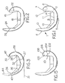
- FIGS. 1,2,3,7 and 15 show embodiments of the femoral knee component of the present invention oriented at zero degrees of flexion. Unless otherwise noted, the geometric relationships of this invention are descriptive of a femoral knee implant in this orientation.
- FIG. 1 depicts an exemplary one-piece femoral knee implant 1 according to the present invention.
- the implant 1 includes arcuate medial 2 and lateral (not shown) condyles joined together at their anterior aspects to form a patellar flange 4.
- Each of the medial 2 and lateral condyles includes a distal condyle 5, a posterior condyle 6, and a superior condyle 7.
- the patellar flange 4, the distal condyles 5, the posterior condyles 6, and the superior condyles 7 define a smooth articular surface extending around the exterior of the implant 1.
- the interior of the implant 1 is defined by a box 9.
- the box 9 includes an anterior box surface 10, a distal box surface 11 and a posterior box surface 12.
- the anterior 10 and the distal 11 box surfaces are blended by an anterior chamfer surface 13.
- the distal 11 and posterior 12 box surfaces are blended by a posterior chamfer surface 14.
- the four compartment knee of the present invention accommodates flexion
- the superior aspect of the posterior condyles 6 is extended toward the anterior flange 4 to allow the articular surface to extend further around and back anteriorly than with prior femoral implants.
- Extending the superior aspect ofthe posterior condyle can be done in several ways. As shown in FIG. 1, the entire posterior condyle is thickened such that the posterior box surface 12 is further from the posterior condyle 6 exterior surface and nearer the anterior box surface 10. This widens the superior aspect of the posterior condyle so that the articular surface can be extended to form the superior condyle 7.
- posterior condyle 6 can be shortened by removing material from the superior aspect where the condyle begins to taper which will have the effect of leaving a thicker superior aspect that can be shaped into a superior condyle.
- Yet another alternative is to change the angle that the posterior box surface 12 makes with the distal box surface 11. By making the included angle between these two surface smaller, the superior aspect of the posterior condyle is made wider to provide for a superior condyle 7.
- the angle between the posterior box surface 16 and the distal box surface 18 has been made less than 90 degrees to provide ample width for a superior condyle 20.
- the dashed line 22 depicts the angle of the posterior box surface of a typical prior art femoral component.
- posterior box surfaces 16 and the anterior box surface 24 must be parallel or slightly diverging toward the box opening. Therefore it may be necessary, as shown in FIG. 2, where the posterior box surface has been angled inwardly, to angle the anterior box surface 24 outwardly.
- the dashed line 26 depicts the angle of the anterior box surface of a typical prior art femoral component.
- FIG. 3 illustrates another alternative embodiment for moving the superior aspect of the posterior condyle 28 anteriorly.
- the entire box including the posterior surface 30, distal surface 32, anterior surface 34 and chamfers 36 and 38; is rotated about a medial-lateral axis thus shortening the anterior condyle 40 and extending the posterior condyle 28 anteriorly and slightly superiorly.
- a superior condyle 42 can then be formed at the superior aspect of the posterior condyle 28.
- the dashed lines 44 depict the box and articular surfaces of a typical prior art femoral component before the box is rotated.
- the distal box surface 27 (dashed) is parallel to the tangent 31 of the distal condyles at their most prominent point. This helps a surgeon orient the femoral component at full extension.
- the box is rotated so that the distal surface 32 is angled relative to the tangent 31.
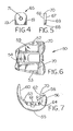
- FIGS. 4-7 depict an alternative modular embodiment of the invention.
- the use of a modular add-on allows a conventional implant to be adapted for four compartment articulation.
- the implant 50 includes arcuate medial 52 and lateral 53 condyles joined together at their anterior aspects to form a patellar flange 54.
- Each of the medial 52 and lateral 53 condyles is made up of a distal condyle 55 and a posterior condyle 56.
- the patellar flange 54, the distal condyles 55 and the posterior condyles 56 define a smooth articular surface extending around the exterior of the implant 50.
- the articular surface terminates at the apexes 58 of the posterior condyles 56.
- the terminal portion of the articular surface is defined by the radius R.
- the interior of the implant 1 is defined by a box 59.
- the box 59 includes an anterior box surface 60, a distal box surface 61 and a posterior box surface 62.
- the anterior 60 and distal 61 box surfaces are blended by an anterior chamfer surface 63.
- the distal 61 and posterior 62 box surfaces are blended by a posterior chamfer surface 64.
- FIGS. 4 and 5 depict an articular surface module 65.
- the module 65 includes a front surface 66, a back surface 67, a bottom surface 68, side surfaces 69, and a top surface 70.
- the back 67 and bottom 68 of the module 65 are shaped to seat against the posterior box surface 62 and posterior chamfer surface 64 respectively.
- the top surface 70 has an articular shape matching the articular surface of the implant 50 near the apexes 58.
- the top 70 of the module forms an extension of the articular surface, or a superior fourth compartment, as shown in FIGS. 6 and 7.
- the extended articular surface blends functionally with the articular surface to allow additional articulation of the femur relative to the tibia.
- a smooth transition is provided from articulation on the implant to articulation on the module.
- the module 65 extends the radius R.
- a module is used similarly on both the medial and lateral posterior condyles.
- a through hole 71 in the module 65 and corresponding threaded holes in the posterior condyles allow the module 65 to be securely attached to the implant 50.
- Other well known means of attachment may also be used such as cement or clips.
- FIGS. 8-14 illustrate the femoral component 1 of FIG. 1 articulating with a tibial component 80.
- the tibial component 80 includes a spine 82 having an articular surface 84.
- the femoral component 1 includes a cam 90 having an articular surface 92. In flexion, the cam articular surface 92 bears on the spine articular surface 84.
- This spine/cam interaction creates a center for rotation of the femoral component relative to the tibial component and prevents anterior subluxation of the femoral component relative to the tibial component.
- the distance from the spine/cam contact to the top of the spine is called the "jump height" and is a measure of the subluxation resistance of a particular spine/cam combination because the cam would have to jump over the spine for subluxation to occur.
- jump height is of increased concern.
- bending of the spine is a concern due to increased loads during activities such as squatting.
- the cam is located relatively low compared to the top of the distal condyles.
- the cam begins to ride up the spine and the jump height can be significantly shortened leading to an increased possibility of subluxation and an increased possibility of bending the spine because of the greater bending moment.
- a high cam placement is used similar to the design of the NexGen ® Complete Knee Solution manufactured and sold by Zimmer, Inc.
- the extreme flexion potential of the knee is enhanced. Extreme flexion is facilitated while maintaining a safe level of subluxation resistance.
- the jump height increases from 90 degrees, FIG. 8, to approximately 130 degrees, FIG. 12. Beyond 130 degrees, the cam rises only slightly, thus maintaining a large jump height even in deep flexion.
- FIG. 15 further enhances the jump height of the spine cam articulation.
- the exemplary cam in FIGS. 1 and 8-14 is cylindrical at its functional articulating surface. It is placed far superiorly between the superior posterior condyles to increase jump height in flexion.
- the cam in FIGS. 15-22 is made non-cylindrical, being made up of blended circles or other geometries.
- An exemplary non-cylindrical cam is shown in FIG. 15.
- the cam 100 includes a relatively flat portion 101, a first spine contact portion 102 having a first radius defining a circle, and a second spine contact portion 104 having a second radius defining a circle.
- the first spine contact portion 102 is an arc of the circle defined by the first radius.
- the second spine contact portion 104 is an arc of the circle defined by the second radius.
- the second spine contact portion extends further posteriorly than the perimeter of the circle defined by the first radius.
- the first and second spine contact portions form an ovoid articular surface 102, 104.
- the posterior extension of the cam 100 causes it to reach downwardly and contact the spine lower at higher angles of flexion as shown in FIGS. 16-20.
- the second contact portion 104 causes the femur to roll back in deep flexion to prevent the femoral bone, where it exits the posterior box, from impinging on the tibial articular surface.
- the top 108 of the cam 100 completes the cam profile.
- the cam 100 alternatively includes a third spine contact portion 106, also shown in FIG. 15, having a third radius defining a circle.
- the alternative third spine contact portion projects beyond the condyles in order to maintain the proper femoral position relative to the tibia in deep flexion.
- the radius of the third portion 106 when present, forms the posterior most cam surface and the end of the cam articular surface.
- One way to achieve the described relationships between the spine contacting portions is to increase the radius of the cam 100 posteriorly from the first spine contact portion 102 to the second spine contact portion 104.
- the third spine contacting portion 106 would be made smaller than the second spine contacting portion 104 and would articulate as shown in FIGS. 21 and 22.
- Another way to achieve the inventive relationships is to offset the centers of the first and second radii in the anterior/posterior direction. Depending on the particular radius values and offset chosen, additional radii may be necessary to smoothly blend the first and second spine contacting surfaces.
Landscapes
- Health & Medical Sciences (AREA)
- Orthopedic Medicine & Surgery (AREA)
- Physical Education & Sports Medicine (AREA)
- Cardiology (AREA)
- Oral & Maxillofacial Surgery (AREA)
- Transplantation (AREA)
- Engineering & Computer Science (AREA)
- Biomedical Technology (AREA)
- Heart & Thoracic Surgery (AREA)
- Vascular Medicine (AREA)
- Life Sciences & Earth Sciences (AREA)
- Animal Behavior & Ethology (AREA)
- General Health & Medical Sciences (AREA)
- Public Health (AREA)
- Veterinary Medicine (AREA)
- Prostheses (AREA)
Claims (10)
- Prothèse de genou incluant :un composant tibial comprenant une surface articulaire tibiale et ;un composant fémoral (1) comprenant des condyles arqués médians (2) et latéraux assemblés afin de former un rebord patellaire (4), chacun des condyles médians (2) et latéraux incluant un condyle distal (5), un condyle postérieur (6) et un condyle supérieur (7), les faces supérieures (7) des condyles postérieurs (6) s'étendant vers le rebord antérieur (4) et les condyles supérieurs (7) étant formés sur la face supérieure, de sorte que le rebord patellaire (4), les condyles distaux (5), les condyles postérieurs (6) et les condyles supérieurs (7) définissent une surface articulaire lisse s'étendant sur le pourtour extérieur de l'implant (1) pour s'articuler avec la surface articulaire tibiale, les condyles supérieurs (7) étendant la surface articulaire jusqu'à l'arrière du rebord patellaire (4) afin de permettre la flexion du composant fémoral (1) par rapport au composant tibial d'au moins 160 degrés, caractérisée en ce que le composant fémoral (1) inclut de plus un intérieur creux délimité par une surface plane antérieure opposée au rebord patellaire (4), des surfaces planes distales (18) opposées aux condyles distaux (5) et des surfaces planes postérieures (16) opposées aux condyles postérieurs (6), caractérisée en ce que les surfaces planes antérieure (24) et distale (18) sont assemblées par une surface plane de chanfrein antérieur, les surfaces planes distale (18) et postérieure (16) sont assemblées par une surface plane de chanfrein postérieur, l'angle inclus entre les surfaces planes distale (18) et postérieure (16) étant inférieur à 90 degrés.
- Prothèse de genou selon la revendication 1 caractérisée en ce que le composant fémoral (1) inclut en plus un intérieur creux délimité par une surface plane antérieure (34) opposée au rebord patellaire (4), des surfaces planes distales (32) opposées aux condyles distaux, et des surfaces planes postérieures (30) opposées aux condyles postérieurs (28), les surfaces planes antérieure (34) et distale (32) étant réunies par une surface plane de chanfrein antérieur (36), les surfaces planes distale (32) et postérieure (30) étant assemblées par une surface plane de chanfrein postérieur (38), les condyles distaux (27) ayant une tangente (31) à leur point distal de plus proéminent, la surface plane distale (32) s'éloignant de la tangente (31) vers l'arrière.
- Prothèse de genou selon la revendication 1 caractérisée en ce que le composant tibial (80) inclut une butée (82) s'étendant à partir de la surface articulaire tibiale, la butée (82) ayant une surface supérieure au plus loin de la surface articulaire tibiale et une surface articulaire (84), et le composant fémoral (1) inclut une came (90) entre les condyles postérieurs supérieurs (7), la came (90) ayant une surface articulaire (92), la surface articulaire de la came (92) étant en contact avec la surface articulaire de la butée (84) à divers endroits verticaux lorsque les composants fémoral (1) et tibial (80) fléchissent l'un par rapport au-delà de 90 degrés, la distance entre le contact entre les surfaces articulaires de la came (90) et de la butée (84) et la surface supérieure de la butée étant plus grande à 130 degrés qu'à 90 degrés.
- Prothèse de genou selon la revendication 3 caractérisée en ce que la distance entre le contact entre les surfaces articulaires de la came (92) et de la butée (84) et la surface supérieure de la butée est approximativement la même pour les angles de flexion de 130 à 160 degrés.
- Prothèse de genou selon la revendication 1 caractérisée en ce que le composant tibial (80) inclut une butée (82) s'étendant à partir de la surface articulaire tibiale, la butée (82) ayant une surface supérieure au plus loin de la surface articulaire tibiale et une surface articulaire (84), et le composant fémoral (1) inclut une came (100) entre les condyles postérieurs supérieurs, la came (100) ayant une surface articulaire non cylindrique avec une première partie de contact avec la butée (102) et une seconde partie de contact avec la butée (104) située plus en arrière que la première partie de contact avec la butée (102).
- Prothèse de genou selon la revendication 5 caractérisée en ce que la première partie de contact avec la butée (102) a un premier rayon définissant un premier cercle et la seconde partie de contact avec la butée (104) a un second rayon définissant un second cercle, la première partie de contact avec la butée (102) étant un arc du premier cercle et la seconde partie de contact avec la butée (104) étant un arc du second cercle, la seconde partie de contact avec le plateau (104) s'étendant plus loin en arrière du périmètre du premier cercle.
- Prothèse de genou selon la revendication 5 caractérisée en ce que la surface articulaire de la came a une surface incurvée dont le rayon augmente de la première partie de contact (102) à la seconde partie de contact (104).
- Prothèse de genou selon la revendication 5 caractérisée en ce que la première partie de contact avec la butée (102) a un rayon et la seconde partie de contact avec la butée (104) a un rayon, le rayon de la seconde partie de contact avec la butée (104) étant plus grand que le rayon de la première partie de contact avec la butée (102).
- Prothèse de genou selon la revendication 8 caractérisée en ce que la came (100) a une troisième partie de contact avec la butée (106) située plus en arrière que la seconde partie de contact avec la butée (104) et ayant un troisième rayon, le troisième rayon étant plus petit que le second rayon.
- Prothèse de genou selon la revendication 9 caractérisée en ce que la troisième partie de contact avec la butée (106) s'étend plus en arrière que les condyles postérieurs.
Priority Applications (1)
| Application Number | Priority Date | Filing Date | Title |
|---|---|---|---|
| EP04030369A EP1518521B1 (fr) | 1998-03-10 | 1999-03-09 | Prothèse de genou à quatre compartiments articulaires |
Applications Claiming Priority (2)
| Application Number | Priority Date | Filing Date | Title |
|---|---|---|---|
| US09/037,417 US6123729A (en) | 1998-03-10 | 1998-03-10 | Four compartment knee |
| US37417 | 1998-03-10 |
Related Child Applications (1)
| Application Number | Title | Priority Date | Filing Date |
|---|---|---|---|
| EP04030369A Division EP1518521B1 (fr) | 1998-03-10 | 1999-03-09 | Prothèse de genou à quatre compartiments articulaires |
Publications (3)
| Publication Number | Publication Date |
|---|---|
| EP0941719A2 EP0941719A2 (fr) | 1999-09-15 |
| EP0941719A3 EP0941719A3 (fr) | 2001-09-05 |
| EP0941719B1 true EP0941719B1 (fr) | 2004-12-22 |
Family
ID=21894222
Family Applications (2)
| Application Number | Title | Priority Date | Filing Date |
|---|---|---|---|
| EP04030369A Expired - Lifetime EP1518521B1 (fr) | 1998-03-10 | 1999-03-09 | Prothèse de genou à quatre compartiments articulaires |
| EP99200699A Expired - Lifetime EP0941719B1 (fr) | 1998-03-10 | 1999-03-09 | Prothèse de genou à quatre compartiments articulaires |
Family Applications Before (1)
| Application Number | Title | Priority Date | Filing Date |
|---|---|---|---|
| EP04030369A Expired - Lifetime EP1518521B1 (fr) | 1998-03-10 | 1999-03-09 | Prothèse de genou à quatre compartiments articulaires |
Country Status (7)
| Country | Link |
|---|---|
| US (2) | US6123729A (fr) |
| EP (2) | EP1518521B1 (fr) |
| JP (1) | JP4290803B2 (fr) |
| AU (1) | AU737463B2 (fr) |
| CA (2) | CA2263086C (fr) |
| DE (2) | DE69942549D1 (fr) |
| ES (2) | ES2346434T3 (fr) |
Cited By (10)
| Publication number | Priority date | Publication date | Assignee | Title |
|---|---|---|---|---|
| US7520901B2 (en) | 2001-06-14 | 2009-04-21 | Alexandria Research Technologies, Inc. | Bicompartmental implants and method of use |
| US7935151B2 (en) | 2001-03-05 | 2011-05-03 | Hudson Surgical Design, Inc. | Femoral prosthetic implant |
| US7967822B2 (en) | 1994-09-02 | 2011-06-28 | Hudson Surgical Design, Inc. | Methods and apparatus for orthopedic implants |
| US8021368B2 (en) | 2004-01-14 | 2011-09-20 | Hudson Surgical Design, Inc. | Methods and apparatus for improved cutting tools for resection |
| US8114083B2 (en) | 2004-01-14 | 2012-02-14 | Hudson Surgical Design, Inc. | Methods and apparatus for improved drilling and milling tools for resection |
| US8287545B2 (en) | 2004-01-14 | 2012-10-16 | Hudson Surgical Design, Inc. | Methods and apparatus for enhanced retention of prosthetic implants |
| US8394147B2 (en) | 2002-12-20 | 2013-03-12 | Smith & Nephew, Inc. | High performance femoral knee prostheses |
| US8603095B2 (en) | 1994-09-02 | 2013-12-10 | Puget Bio Ventures LLC | Apparatuses for femoral and tibial resection |
| US8740906B2 (en) | 2004-01-14 | 2014-06-03 | Hudson Surgical Design, Inc. | Method and apparatus for wireplasty bone resection |
| US8926709B2 (en) | 2010-08-12 | 2015-01-06 | Smith & Nephew, Inc. | Structures for use in orthopaedic implant fixation and methods of installation onto a bone |
Families Citing this family (113)
| Publication number | Priority date | Publication date | Assignee | Title |
|---|---|---|---|---|
| US9603711B2 (en) | 2001-05-25 | 2017-03-28 | Conformis, Inc. | Patient-adapted and improved articular implants, designs and related guide tools |
| US8882847B2 (en) | 2001-05-25 | 2014-11-11 | Conformis, Inc. | Patient selectable knee joint arthroplasty devices |
| US8556983B2 (en) | 2001-05-25 | 2013-10-15 | Conformis, Inc. | Patient-adapted and improved orthopedic implants, designs and related tools |
| US8480754B2 (en) | 2001-05-25 | 2013-07-09 | Conformis, Inc. | Patient-adapted and improved articular implants, designs and related guide tools |
| US8545569B2 (en) * | 2001-05-25 | 2013-10-01 | Conformis, Inc. | Patient selectable knee arthroplasty devices |
| ATE439806T1 (de) | 1998-09-14 | 2009-09-15 | Univ Leland Stanford Junior | Zustandsbestimmung eines gelenks und schadenvorsorge |
| US6443991B1 (en) | 1998-09-21 | 2002-09-03 | Depuy Orthopaedics, Inc. | Posterior stabilized mobile bearing knee |
| US6972039B2 (en) | 1999-03-01 | 2005-12-06 | Biomet, Inc. | Floating bearing knee joint prosthesis with a fixed tibial post |
| US6413279B1 (en) | 1999-03-01 | 2002-07-02 | Biomet, Inc. | Floating bearing knee joint prosthesis with a fixed tibial post |
| DE29906909U1 (de) | 1999-03-02 | 1999-09-30 | Plus Endoprothetik Ag, Rotkreuz | Femurschlitten |
| US6558426B1 (en) | 2000-11-28 | 2003-05-06 | Medidea, Llc | Multiple-cam, posterior-stabilized knee prosthesis |
| US7776085B2 (en) | 2001-05-01 | 2010-08-17 | Amedica Corporation | Knee prosthesis with ceramic tibial component |
| US7695521B2 (en) | 2001-05-01 | 2010-04-13 | Amedica Corporation | Hip prosthesis with monoblock ceramic acetabular cup |
| AU2002324443A1 (en) * | 2001-06-14 | 2003-01-02 | Amedica Corporation | Metal-ceramic composite articulation |
| US6821470B2 (en) * | 2001-06-29 | 2004-11-23 | Depuy Products, Inc. | Joint prosthesis molding method |
| US20030009230A1 (en) * | 2001-06-30 | 2003-01-09 | Gundlapalli Rama Rao V. | Surface sterilizable joint replacement prosthesis component with insert |
| US6695619B2 (en) * | 2001-08-09 | 2004-02-24 | Oliver Brown-Wilkinson | Orthopaedic demonstration aid |
| FR2835738B1 (fr) * | 2002-02-14 | 2004-10-01 | Jacques Afriat | Prothese totale du genou |
| WO2003070127A1 (fr) * | 2002-02-20 | 2003-08-28 | Nemcomed, Ltd. | Prothese d'arthroplastie du genou et procede associe |
| US20070293571A1 (en) * | 2006-06-08 | 2007-12-20 | Hinz Martin C | Adminstration of dopa precursors with sources of dopa to effectuate optimal catecholamine neurotransmitter outcomes |
| US20090311795A1 (en) * | 2002-03-21 | 2009-12-17 | Hinz Martin C | Bilateral control of functions traditionally regulated by only serotonin or only dopamine |
| US7150761B2 (en) * | 2002-05-24 | 2006-12-19 | Medicinelodge, Inc. | Modular femoral components for knee arthroplasty |
| US7615081B2 (en) * | 2002-05-24 | 2009-11-10 | Zimmer, Inc. | Femoral components for knee arthroplasty |
| US20040054416A1 (en) | 2002-09-12 | 2004-03-18 | Joe Wyss | Posterior stabilized knee with varus-valgus constraint |
| FR2844704B1 (fr) * | 2002-09-24 | 2005-06-03 | Biomet Merck France | Prothese de genou a plateau mobile |
| US7799084B2 (en) | 2002-10-23 | 2010-09-21 | Mako Surgical Corp. | Modular femoral component for a total knee joint replacement for minimally invasive implantation |
| EP3075356B1 (fr) | 2002-11-07 | 2023-07-05 | ConforMIS, Inc. | Méthode de sélection d'un implant méniscal |
| US6770099B2 (en) * | 2002-11-19 | 2004-08-03 | Zimmer Technology, Inc. | Femoral prosthesis |
| US20040102852A1 (en) | 2002-11-22 | 2004-05-27 | Johnson Erin M. | Modular knee prosthesis |
| US6749638B1 (en) * | 2002-11-22 | 2004-06-15 | Zimmer Technology, Inc. | Modular knee prosthesis |
| US6994727B2 (en) * | 2002-12-17 | 2006-02-07 | Amedica Corporation | Total disc implant |
| ES2304601T3 (es) * | 2003-02-08 | 2008-10-16 | Depuy International Limited | Protesis de articulacion de rodilla. |
| FR2855963B1 (fr) * | 2003-06-13 | 2005-11-18 | X Nov | Prothese femorale a bec protecteur |
| AU2004281743B2 (en) | 2003-10-17 | 2011-06-09 | Smith & Nephew, Inc. | High flexion articular insert |
| US8002840B2 (en) | 2004-01-12 | 2011-08-23 | Depuy Products, Inc. | Systems and methods for compartmental replacement in a knee |
| US8535383B2 (en) * | 2004-01-12 | 2013-09-17 | DePuy Synthes Products, LLC | Systems and methods for compartmental replacement in a knee |
| CN1972646B (zh) * | 2004-01-12 | 2010-05-26 | 德普伊产品公司 | 用于膝中隔间置换的系统和方法 |
| US7544209B2 (en) | 2004-01-12 | 2009-06-09 | Lotke Paul A | Patello-femoral prosthesis |
| JP3915989B2 (ja) | 2004-03-17 | 2007-05-16 | 徹 勝呂 | 人工膝関節 |
| US20090036993A1 (en) * | 2004-04-22 | 2009-02-05 | Robert Metzger | Patellar implant |
| US7731755B2 (en) * | 2004-06-11 | 2010-06-08 | Depuy Products, Inc. | Posterior stabilized mobile bearing knee |
| US8852195B2 (en) | 2004-07-09 | 2014-10-07 | Zimmer, Inc. | Guide templates for surgical implants and related methods |
| US20070100461A1 (en) * | 2005-04-12 | 2007-05-03 | The University Of Vermont And State Agriculture College | Knee prosthesis |
| GB0510193D0 (en) * | 2005-05-19 | 2005-06-22 | Mcminn Derek J W | Knee prosthesis |
| JP4887292B2 (ja) * | 2005-07-14 | 2012-02-29 | 国立大学法人佐賀大学 | 人工膝関節 |
| US20070135921A1 (en) * | 2005-12-09 | 2007-06-14 | Park Kee B | Surgical implant |
| US8292964B2 (en) * | 2005-12-14 | 2012-10-23 | New York University | Surface guided knee replacement |
| US8211181B2 (en) * | 2005-12-14 | 2012-07-03 | New York University | Surface guided knee replacement |
| US8070821B2 (en) * | 2005-12-27 | 2011-12-06 | Howmedica Osteonics Corp. | Hybrid femoral implant |
| US20070179609A1 (en) * | 2006-01-27 | 2007-08-02 | Medicinelodge, Inc. | Therapeutic agent eluding implant with percutaneous supply |
| EP2478873B1 (fr) | 2006-03-21 | 2014-05-28 | DePuy (Ireland) | Prothèse d'arthroplastie totale à moments induits |
| US20070225819A1 (en) * | 2006-03-24 | 2007-09-27 | Depuy Products, Inc. | Apparatus and method for the treatment of periprosthetic fractures |
| WO2008005905A1 (fr) | 2006-06-30 | 2008-01-10 | Smith & Nephew, Inc. | Prothèse articulée pour un mouvement anatomique |
| DE102006042829A1 (de) * | 2006-09-08 | 2008-03-27 | Siebel, Thomas, Dr. | Knieprothese |
| WO2008101090A2 (fr) | 2007-02-14 | 2008-08-21 | Conformis, Inc. | Dispositif d'implant et procédé de fabrication |
| US8382846B2 (en) | 2007-08-27 | 2013-02-26 | Kent M. Samuelson | Systems and methods for providing deeper knee flexion capabilities for knee prosthesis patients |
| US9872774B2 (en) | 2007-08-27 | 2018-01-23 | Connor E. Samuelson | Systems and methods for providing a femoral component having a modular stem |
| US9107769B2 (en) | 2007-08-27 | 2015-08-18 | Kent M. Samuelson | Systems and methods for providing a femoral component |
| US8273133B2 (en) * | 2007-08-27 | 2012-09-25 | Samuelson Kent M | Systems and methods for providing deeper knee flexion capabilities for knee prosthesis patients |
| US8366783B2 (en) | 2007-08-27 | 2013-02-05 | Samuelson Kent M | Systems and methods for providing deeper knee flexion capabilities for knee prosthesis patients |
| US20160310279A1 (en) | 2007-08-27 | 2016-10-27 | Connor E. Samuelson | Systems and methods for providing lightweight prosthetic components |
| US8292965B2 (en) * | 2008-02-11 | 2012-10-23 | New York University | Knee joint with a ramp |
| CN102006839B (zh) * | 2008-02-18 | 2014-07-23 | 麦克斯外科整形公司 | 全膝关节置换假体 |
| US8682052B2 (en) | 2008-03-05 | 2014-03-25 | Conformis, Inc. | Implants for altering wear patterns of articular surfaces |
| AU2009246474B2 (en) | 2008-05-12 | 2015-04-16 | Conformis, Inc. | Devices and methods for treatment of facet and other joints |
| WO2010008803A2 (fr) * | 2008-06-24 | 2010-01-21 | Walker Peter S | Prothèse d’articulation de genou à rampe et à empreintes |
| AU2015203508B2 (en) * | 2008-06-30 | 2017-08-17 | Depuy Products, Inc. | Orthopaedic knee prosthesis having controlled condylar curvature |
| US8206451B2 (en) | 2008-06-30 | 2012-06-26 | Depuy Products, Inc. | Posterior stabilized orthopaedic prosthesis |
| US8187335B2 (en) | 2008-06-30 | 2012-05-29 | Depuy Products, Inc. | Posterior stabilized orthopaedic knee prosthesis having controlled condylar curvature |
| US8828086B2 (en) | 2008-06-30 | 2014-09-09 | Depuy (Ireland) | Orthopaedic femoral component having controlled condylar curvature |
| US8192498B2 (en) | 2008-06-30 | 2012-06-05 | Depuy Products, Inc. | Posterior cructiate-retaining orthopaedic knee prosthesis having controlled condylar curvature |
| US9119723B2 (en) | 2008-06-30 | 2015-09-01 | Depuy (Ireland) | Posterior stabilized orthopaedic prosthesis assembly |
| US9168145B2 (en) | 2008-06-30 | 2015-10-27 | Depuy (Ireland) | Posterior stabilized orthopaedic knee prosthesis having controlled condylar curvature |
| US8236061B2 (en) | 2008-06-30 | 2012-08-07 | Depuy Products, Inc. | Orthopaedic knee prosthesis having controlled condylar curvature |
| US8202323B2 (en) * | 2008-07-16 | 2012-06-19 | Depuy Products, Inc. | Knee prostheses with enhanced kinematics |
| US8715358B2 (en) * | 2008-07-18 | 2014-05-06 | Michael A. Masini | PCL retaining ACL substituting TKA apparatus and method |
| US9220600B2 (en) | 2008-12-23 | 2015-12-29 | Aesculap Implant Systems, Llc | Knee prosthesis |
| US8491662B2 (en) | 2008-12-23 | 2013-07-23 | Aesculap Ag | Knee prosthesis |
| US20100161067A1 (en) * | 2008-12-23 | 2010-06-24 | Aesculap Ag | Knee prosthesis |
| EP2405865B1 (fr) | 2009-02-24 | 2019-04-17 | ConforMIS, Inc. | Systèmes automatisés four la fabrication des implants et instruments adaptés individuellement au patient |
| US9452052B2 (en) * | 2009-03-27 | 2016-09-27 | Smith And Nephew Orthopaedics Ag | Artificial knee joint |
| US8915965B2 (en) * | 2009-05-07 | 2014-12-23 | Depuy (Ireland) | Anterior stabilized knee implant |
| EP2272466A1 (fr) * | 2009-07-10 | 2011-01-12 | Medizinische Hochschule Hannover | Prothèse du genou et procédé de fabrication |
| AU2010327987B2 (en) | 2009-12-11 | 2015-04-02 | Conformis, Inc. | Patient-specific and patient-engineered orthopedic implants |
| US8308808B2 (en) | 2010-02-19 | 2012-11-13 | Biomet Manufacturing Corp. | Latent mobile bearing for prosthetic device |
| CN103153237B (zh) | 2010-07-24 | 2016-01-20 | 捷迈有限公司 | 用于膝部假体的非对称胫骨部件 |
| US8628580B2 (en) | 2010-07-24 | 2014-01-14 | Zimmer, Inc. | Tibial prosthesis |
| EP3348236B1 (fr) | 2010-09-10 | 2019-11-20 | Zimmer, Inc. | Composants tibiaux facilitant le mouvement pour une prothèse du genou |
| US8317870B2 (en) | 2010-09-30 | 2012-11-27 | Depuy Products, Inc. | Tibial component of a knee prosthesis having an angled cement pocket |
| US8603101B2 (en) | 2010-12-17 | 2013-12-10 | Zimmer, Inc. | Provisional tibial prosthesis system |
| US8403994B2 (en) | 2011-01-19 | 2013-03-26 | Wright Medical Technology, Inc. | Knee implant system |
| SG193484A1 (en) | 2011-02-15 | 2013-10-30 | Conformis Inc | Patent-adapted and improved articular implants, designs, surgical procedures and related guide tools |
| US8747479B2 (en) | 2011-04-26 | 2014-06-10 | Michael A. McShane | Tibial component |
| JP6029817B2 (ja) | 2011-09-27 | 2016-11-24 | 京セラメディカル株式会社 | 人工膝関節インプラント |
| AU2012227339B2 (en) * | 2011-09-30 | 2015-07-02 | Depuy Products, Inc. | Tibial component of a knee prosthesis having an angled cement pocket |
| EP3848005B1 (fr) | 2011-11-18 | 2025-04-23 | Zimmer, Inc. | Élément porteur tibial pour prothèse du genou présentant des caractéristiques articulaires améliorées |
| CN104093380B (zh) | 2011-11-21 | 2016-08-31 | 捷迈有限公司 | 具有不对称设置的固定结构的胫骨基板 |
| CN103126787B (zh) | 2011-11-28 | 2015-03-04 | 北京纳通科技集团有限公司 | 一种膝关节假体 |
| KR20140133836A (ko) | 2012-01-30 | 2014-11-20 | 짐머, 인크. | 무릎 보철물을 위한 비대칭 경골 부재 |
| WO2014209916A1 (fr) * | 2013-06-23 | 2014-12-31 | Hunter William L | Dispositifs, systèmes et procédés de surveillance de remplacements du genou |
| US9925052B2 (en) | 2013-08-30 | 2018-03-27 | Zimmer, Inc. | Method for optimizing implant designs |
| ITMI20132154A1 (it) * | 2013-12-20 | 2015-06-21 | Adler Ortho S R L | Componente femorale per protesi di ginocchio. |
| WO2015118517A1 (fr) | 2014-02-10 | 2015-08-13 | Limacorporate S.P.A. | Articulation artificielle de genou |
| JP6470541B2 (ja) * | 2014-10-21 | 2019-02-13 | 京セラ株式会社 | 人工膝関節インプラント |
| WO2017053196A1 (fr) | 2015-09-21 | 2017-03-30 | Zimmer, Inc. | Système de prothèse comprenant un composant de support tibial |
| US10179052B2 (en) | 2016-07-28 | 2019-01-15 | Depuy Ireland Unlimited Company | Total knee implant prosthesis assembly and method |
| CN106580524B (zh) * | 2016-12-12 | 2018-08-07 | 上海昕健医疗技术有限公司 | 后稳定型膝关节假体 |
| FR3060970B1 (fr) * | 2016-12-26 | 2019-02-01 | X Nov Ip | Partie femorale d'une prothese de genou |
| EP4541322A3 (fr) | 2017-03-10 | 2025-06-18 | Zimmer, Inc. | Prothèse tibiale présentant un élément de fixation pour l'élément porteur tibial |
| CA3063415C (fr) | 2017-05-12 | 2021-10-19 | Zimmer, Inc. | Protheses femorales presentant des capacites d'agrandissement et de reduction de taille |
| US11426282B2 (en) | 2017-11-16 | 2022-08-30 | Zimmer, Inc. | Implants for adding joint inclination to a knee arthroplasty |
| US10307255B1 (en) | 2017-11-29 | 2019-06-04 | b-ONE Ortho, Corp. | Acetabular cup assembly |
| US10835380B2 (en) | 2018-04-30 | 2020-11-17 | Zimmer, Inc. | Posterior stabilized prosthesis system |
Family Cites Families (46)
| Publication number | Priority date | Publication date | Assignee | Title |
|---|---|---|---|---|
| GB1445684A (en) * | 1972-10-19 | 1976-08-11 | Nat Res Dev | Endoprosthetic bone joint devices |
| GB1507309A (en) * | 1974-10-14 | 1978-04-12 | Atomic Energy Authority Uk | Prosthetic knee joints |
| US4209861A (en) * | 1978-02-22 | 1980-07-01 | Howmedica, Inc. | Joint prosthesis |
| US4213209A (en) * | 1978-05-22 | 1980-07-22 | New York Society For The Relief Of The Ruptured And Crippled | Knee joint prosthesis |
| US4224697A (en) * | 1978-09-08 | 1980-09-30 | Hexcel Corporation | Constrained prosthetic knee |
| CH632151A5 (de) * | 1978-10-06 | 1982-09-30 | Sulzer Ag | Endoprothese fuer ein kniegelenk. |
| US4298992A (en) * | 1980-01-21 | 1981-11-10 | New York Society For The Relief Of The Ruptured And Crippled | Posteriorly stabilized total knee joint prosthesis |
| US4353136A (en) * | 1980-11-05 | 1982-10-12 | Polyzoides Apostolos J | Endoprosthetic knee joint |
| EP0103697A1 (fr) * | 1982-09-22 | 1984-03-28 | GebràDer Sulzer Aktiengesellschaft | Prothèse pour l'articulation du genou |
| JPS6077752A (ja) * | 1983-09-30 | 1985-05-02 | 東海林 宏 | メニスカル人工膝関節 |
| US4634444A (en) * | 1984-02-09 | 1987-01-06 | Joint Medical Products Corporation | Semi-constrained artificial joint |
| GB8432267D0 (en) * | 1984-12-20 | 1985-01-30 | Thackray C F Ltd | Knee prosthesis |
| US4714474A (en) * | 1986-05-12 | 1987-12-22 | Dow Corning Wright Corporation | Tibial knee joint prosthesis with removable articulating surface insert |
| FR2615386A1 (fr) * | 1987-05-21 | 1988-11-25 | Tornier Sa | Prothese totale de genou |
| FR2621243A1 (fr) * | 1987-10-06 | 1989-04-07 | Cuilleron J | Prothese totale du genou |
| US5011496A (en) * | 1988-02-02 | 1991-04-30 | Joint Medical Products Corporation | Prosthetic joint |
| US4888021A (en) * | 1988-02-02 | 1989-12-19 | Joint Medical Products Corporation | Knee and patellar prosthesis |
| US4892547A (en) * | 1988-02-03 | 1990-01-09 | Biomet, Inc. | Partially stabilized knee prosthesis |
| US4959071A (en) * | 1988-02-03 | 1990-09-25 | Biomet, Inc. | Partially stabilized knee prosthesis |
| US5035700A (en) * | 1988-02-03 | 1991-07-30 | Pfizer Hospital Products Group, Inc. | Prosthetic knee joint with improved patellar component tracking |
| US4950298A (en) | 1988-04-08 | 1990-08-21 | Gustilo Ramon B | Modular knee joint prosthesis |
| FR2631814A1 (fr) * | 1988-05-31 | 1989-12-01 | Scernp | Prothese a glissement pour le genou |
| GB2223950B (en) * | 1988-10-18 | 1992-06-17 | Univ London | Knee prosthesis |
| US4936847A (en) * | 1988-12-27 | 1990-06-26 | Johnson & Johnson Orthopaedics, Inc. | Revision knee prosthesis |
| CA2006152C (fr) * | 1988-12-27 | 1999-03-23 | John Edward Slamin | Prothese modulaire du genou |
| US5007933A (en) * | 1989-01-31 | 1991-04-16 | Osteonics Corp. | Modular knee prosthesis system |
| GB8912682D0 (en) * | 1989-06-02 | 1989-07-19 | Thackray Chas F | Improvements in and relating to knee prosthesis |
| US5147405A (en) * | 1990-02-07 | 1992-09-15 | Boehringer Mannheim Corporation | Knee prosthesis |
| JPH03267055A (ja) * | 1990-03-16 | 1991-11-27 | Koshino Nariko | 人工膝関節の脛骨側コンポーネント |
| US5116375A (en) * | 1990-08-27 | 1992-05-26 | Hofmann Aaron A | Knee prosthesis |
| US5236461A (en) * | 1991-03-22 | 1993-08-17 | Forte Mark R | Totally posterior stabilized knee prosthesis |
| US5358527A (en) * | 1991-03-22 | 1994-10-25 | Forte Mark R | Total knee prosthesis with resurfacing and posterior stabilization capability |
| US5181925A (en) * | 1991-04-22 | 1993-01-26 | Zimmer, Inc. | Femoral component for a knee joint prosthesis having a modular cam and stem |
| US5330534A (en) * | 1992-02-10 | 1994-07-19 | Biomet, Inc. | Knee joint prosthesis with interchangeable components |
| NZ243181A (en) * | 1992-04-23 | 1994-10-26 | Michael John Pappas | Prosthetic joint with guide means to limit articulation of a first element and bearing means to two degrees of freedom |
| US5370699A (en) * | 1993-01-21 | 1994-12-06 | Orthomet, Inc. | Modular knee joint prosthesis |
| FR2701387B1 (fr) * | 1993-02-10 | 1995-06-23 | Reach | Prothese du genou postero-stabilisee. |
| US5358530A (en) * | 1993-03-29 | 1994-10-25 | Zimmer, Inc. | Mobile bearing knee |
| FR2718015B1 (fr) * | 1994-03-29 | 1996-07-05 | Bouvet Jean Claude | Perfectionnement aux prothèses de genou. |
| US5549686A (en) * | 1994-06-06 | 1996-08-27 | Zimmer, Inc. | Knee prosthesis having a tapered cam |
| DE69514386T2 (de) * | 1994-10-28 | 2000-07-27 | Sulzer Orthopedics Inc., Austin | Knieprothese mit einsätzen |
| US5571194A (en) * | 1994-11-14 | 1996-11-05 | Johnson & Johnson Professional, Inc. | Femoral augmentation system for artificial knee joint |
| US5984969A (en) * | 1995-06-01 | 1999-11-16 | Johnson & Johnson Professional, Inc. | Joint prosthesis augmentation system |
| AU701181B2 (en) * | 1995-06-01 | 1999-01-21 | Depuy Orthopaedics, Inc. | Augmentation device for joint prostheses |
| CA2233265C (fr) | 1997-04-04 | 2004-09-14 | T. Derek V. Cooke | Prothese pour genou permettant une profonde flexion |
| US6152960A (en) * | 1998-10-13 | 2000-11-28 | Biomedical Engineering Trust I | Femoral component for knee endoprosthesis |
-
1998
- 1998-03-10 US US09/037,417 patent/US6123729A/en not_active Expired - Lifetime
-
1999
- 1999-02-26 CA CA002263086A patent/CA2263086C/fr not_active Expired - Lifetime
- 1999-02-26 CA CA2629274A patent/CA2629274C/fr not_active Expired - Lifetime
- 1999-03-05 AU AU18595/99A patent/AU737463B2/en not_active Expired
- 1999-03-08 JP JP05964899A patent/JP4290803B2/ja not_active Expired - Lifetime
- 1999-03-09 DE DE69942549T patent/DE69942549D1/de not_active Expired - Lifetime
- 1999-03-09 ES ES04030369T patent/ES2346434T3/es not_active Expired - Lifetime
- 1999-03-09 DE DE69922723T patent/DE69922723T2/de not_active Expired - Lifetime
- 1999-03-09 EP EP04030369A patent/EP1518521B1/fr not_active Expired - Lifetime
- 1999-03-09 EP EP99200699A patent/EP0941719B1/fr not_active Expired - Lifetime
- 1999-03-09 ES ES99200699T patent/ES2234202T3/es not_active Expired - Lifetime
-
2000
- 2000-06-29 US US09/606,608 patent/US6402786B1/en not_active Expired - Lifetime
Cited By (28)
| Publication number | Priority date | Publication date | Assignee | Title |
|---|---|---|---|---|
| US7967822B2 (en) | 1994-09-02 | 2011-06-28 | Hudson Surgical Design, Inc. | Methods and apparatus for orthopedic implants |
| US9066804B2 (en) | 1994-09-02 | 2015-06-30 | Puget Bioventures Llc | Method and apparatus for femoral and tibial resection |
| US8603095B2 (en) | 1994-09-02 | 2013-12-10 | Puget Bio Ventures LLC | Apparatuses for femoral and tibial resection |
| US8430932B2 (en) | 2001-03-05 | 2013-04-30 | Puget Bio Ventures LLC | Femoral prosthetic implant |
| US7935151B2 (en) | 2001-03-05 | 2011-05-03 | Hudson Surgical Design, Inc. | Femoral prosthetic implant |
| US9192391B2 (en) | 2001-03-05 | 2015-11-24 | Puget Bioventures Llc | Method for minimally invasive total knee arthroplasty |
| US8062377B2 (en) | 2001-03-05 | 2011-11-22 | Hudson Surgical Design, Inc. | Methods and apparatus for knee arthroplasty |
| US8088167B2 (en) | 2001-03-05 | 2012-01-03 | Hudson Surgical Design, Inc. | Femoral prosthetic implant |
| US7896922B2 (en) | 2001-06-14 | 2011-03-01 | Alexandria Research Technologies, Llc | Implants for partial knee arthroplasty |
| US7520901B2 (en) | 2001-06-14 | 2009-04-21 | Alexandria Research Technologies, Inc. | Bicompartmental implants and method of use |
| US8652210B2 (en) | 2002-12-20 | 2014-02-18 | Smith & Nephew, Inc. | Femoral prostheses with lateral buttress for patella |
| US8603178B2 (en) | 2002-12-20 | 2013-12-10 | Smith & Nephew, Inc. | Knee prostheses with convex portion on tibial lateral articular surface |
| US8394148B2 (en) | 2002-12-20 | 2013-03-12 | Smith & Nephew, Inc. | Tibial component of high performance knee prosthesis |
| US8398716B2 (en) | 2002-12-20 | 2013-03-19 | Smith & Nephew, Inc. | High performance knee prostheses with posterior cam |
| US8403992B2 (en) | 2002-12-20 | 2013-03-26 | Smith & Nephew, Inc. | High performance knee prostheses |
| US8425617B2 (en) | 2002-12-20 | 2013-04-23 | Smith & Nephew, Inc. | Knee prostheses with convex slope on portion of tibial articular surface |
| US9402729B2 (en) | 2002-12-20 | 2016-08-02 | Smith & Nephew, Inc. | High performance knee prostheses |
| US8449618B2 (en) | 2002-12-20 | 2013-05-28 | Smith & Nephew, Inc. | High performance knee prostheses |
| US9320605B2 (en) | 2002-12-20 | 2016-04-26 | Smith & Nephew, Inc. | High performance knee prostheses |
| US8394147B2 (en) | 2002-12-20 | 2013-03-12 | Smith & Nephew, Inc. | High performance femoral knee prostheses |
| US8647389B2 (en) | 2002-12-20 | 2014-02-11 | Smith & Nephew, Inc. | High performance knee prostheses |
| US8287545B2 (en) | 2004-01-14 | 2012-10-16 | Hudson Surgical Design, Inc. | Methods and apparatus for enhanced retention of prosthetic implants |
| US8740906B2 (en) | 2004-01-14 | 2014-06-03 | Hudson Surgical Design, Inc. | Method and apparatus for wireplasty bone resection |
| US8114083B2 (en) | 2004-01-14 | 2012-02-14 | Hudson Surgical Design, Inc. | Methods and apparatus for improved drilling and milling tools for resection |
| US8021368B2 (en) | 2004-01-14 | 2011-09-20 | Hudson Surgical Design, Inc. | Methods and apparatus for improved cutting tools for resection |
| US8298238B2 (en) | 2004-01-14 | 2012-10-30 | Hudson Surgical Design, Inc. | Methods and apparatus for pivotable guide surfaces for arthroplasty |
| US8353914B2 (en) | 2004-02-02 | 2013-01-15 | Hudson Surgical Design, Inc. | Methods and apparatus for improved profile based resection |
| US8926709B2 (en) | 2010-08-12 | 2015-01-06 | Smith & Nephew, Inc. | Structures for use in orthopaedic implant fixation and methods of installation onto a bone |
Also Published As
| Publication number | Publication date |
|---|---|
| ES2346434T3 (es) | 2010-10-15 |
| CA2629274A1 (fr) | 1999-09-10 |
| EP1518521A3 (fr) | 2005-10-12 |
| DE69922723T2 (de) | 2005-12-15 |
| CA2263086A1 (fr) | 1999-09-10 |
| JPH11313845A (ja) | 1999-11-16 |
| CA2629274C (fr) | 2010-01-26 |
| EP0941719A3 (fr) | 2001-09-05 |
| CA2263086C (fr) | 2008-07-15 |
| JP4290803B2 (ja) | 2009-07-08 |
| ES2234202T3 (es) | 2005-06-16 |
| AU1859599A (en) | 1999-09-23 |
| DE69922723D1 (de) | 2005-01-27 |
| US6123729A (en) | 2000-09-26 |
| EP0941719A2 (fr) | 1999-09-15 |
| EP1518521A2 (fr) | 2005-03-30 |
| DE69942549D1 (de) | 2010-08-12 |
| AU737463B2 (en) | 2001-08-23 |
| US6402786B1 (en) | 2002-06-11 |
| EP1518521B1 (fr) | 2010-06-30 |
Similar Documents
| Publication | Publication Date | Title |
|---|---|---|
| EP0941719B1 (fr) | Prothèse de genou à quatre compartiments articulaires | |
| EP1333785B1 (fr) | Prothese d'articulation de genou a support flottant, comprenant une tige tibiale fixe | |
| US9642711B2 (en) | High flexion articular insert | |
| EP0439505B1 (fr) | Prothese du genou | |
| US7413577B1 (en) | Total stabilized knee prosthesis with constraint | |
| EP2254519B1 (fr) | Prothèse de remplacement du genou complet | |
| US6972039B2 (en) | Floating bearing knee joint prosthesis with a fixed tibial post | |
| CA2449287C (fr) | Prothese femorale | |
| US9289305B2 (en) | Total knee arthroplasty with symmetric femoral implant having double Q-angle trochlear groove | |
| US6506215B1 (en) | Synthetic knee system | |
| US5997577A (en) | Knee joint prosthesis | |
| US6039764A (en) | Prosthetic knee with adjusted center of internal/external rotation | |
| CA1239502A (fr) | Prothese articulaire | |
| WO1996024311A1 (fr) | Prothese stabilisee du genou | |
| US20180161164A1 (en) | Posteriorly stabilized total knee joint prosthesis | |
| AU756267B2 (en) | Four compartment knee | |
| AU2014200110A1 (en) | High flexion articular insert |
Legal Events
| Date | Code | Title | Description |
|---|---|---|---|
| PUAI | Public reference made under article 153(3) epc to a published international application that has entered the european phase |
Free format text: ORIGINAL CODE: 0009012 |
|
| AK | Designated contracting states |
Kind code of ref document: A2 Designated state(s): AT BE CH CY DE DK ES FI FR GB GR IE IT LI LU MC NL PT SE |
|
| AX | Request for extension of the european patent |
Free format text: AL;LT;LV;MK;RO;SI |
|
| PUAL | Search report despatched |
Free format text: ORIGINAL CODE: 0009013 |
|
| AK | Designated contracting states |
Kind code of ref document: A3 Designated state(s): AT BE CH CY DE DK ES FI FR GB GR IE IT LI LU MC NL PT SE |
|
| AX | Request for extension of the european patent |
Free format text: AL;LT;LV;MK;RO;SI |
|
| 17P | Request for examination filed |
Effective date: 20011030 |
|
| AKX | Designation fees paid |
Free format text: DE ES FR GB IT |
|
| 17Q | First examination report despatched |
Effective date: 20030522 |
|
| GRAP | Despatch of communication of intention to grant a patent |
Free format text: ORIGINAL CODE: EPIDOSNIGR1 |
|
| RAP1 | Party data changed (applicant data changed or rights of an application transferred) |
Owner name: INSALL, JOHN NEVIL Owner name: BRISTOL-MYERS SQUIBB COMPANY |
|
| GRAS | Grant fee paid |
Free format text: ORIGINAL CODE: EPIDOSNIGR3 |
|
| GRAA | (expected) grant |
Free format text: ORIGINAL CODE: 0009210 |
|
| AK | Designated contracting states |
Kind code of ref document: B1 Designated state(s): DE ES FR GB IT |
|
| REG | Reference to a national code |
Ref country code: GB Ref legal event code: FG4D |
|
| REF | Corresponds to: |
Ref document number: 69922723 Country of ref document: DE Date of ref document: 20050127 Kind code of ref document: P |
|
| REG | Reference to a national code |
Ref country code: ES Ref legal event code: FG2A Ref document number: 2234202 Country of ref document: ES Kind code of ref document: T3 |
|
| ET | Fr: translation filed | ||
| PLBE | No opposition filed within time limit |
Free format text: ORIGINAL CODE: 0009261 |
|
| STAA | Information on the status of an ep patent application or granted ep patent |
Free format text: STATUS: NO OPPOSITION FILED WITHIN TIME LIMIT |
|
| 26N | No opposition filed |
Effective date: 20050923 |
|
| REG | Reference to a national code |
Ref country code: FR Ref legal event code: PLFP Year of fee payment: 18 |
|
| REG | Reference to a national code |
Ref country code: FR Ref legal event code: PLFP Year of fee payment: 19 |
|
| REG | Reference to a national code |
Ref country code: FR Ref legal event code: PLFP Year of fee payment: 20 |
|
| PGFP | Annual fee paid to national office [announced via postgrant information from national office to epo] |
Ref country code: DE Payment date: 20180227 Year of fee payment: 20 Ref country code: GB Payment date: 20180307 Year of fee payment: 20 |
|
| PGFP | Annual fee paid to national office [announced via postgrant information from national office to epo] |
Ref country code: FR Payment date: 20180223 Year of fee payment: 20 Ref country code: IT Payment date: 20180321 Year of fee payment: 20 |
|
| PGFP | Annual fee paid to national office [announced via postgrant information from national office to epo] |
Ref country code: ES Payment date: 20180402 Year of fee payment: 20 |
|
| REG | Reference to a national code |
Ref country code: DE Ref legal event code: R071 Ref document number: 69922723 Country of ref document: DE |
|
| REG | Reference to a national code |
Ref country code: GB Ref legal event code: PE20 Expiry date: 20190308 |
|
| PG25 | Lapsed in a contracting state [announced via postgrant information from national office to epo] |
Ref country code: GB Free format text: LAPSE BECAUSE OF EXPIRATION OF PROTECTION Effective date: 20190308 |
|
| REG | Reference to a national code |
Ref country code: ES Ref legal event code: FD2A Effective date: 20200724 |
|
| PG25 | Lapsed in a contracting state [announced via postgrant information from national office to epo] |
Ref country code: ES Free format text: LAPSE BECAUSE OF EXPIRATION OF PROTECTION Effective date: 20190310 |