EP0941804A2 - Schleifgerät - Google Patents
Schleifgerät Download PDFInfo
- Publication number
- EP0941804A2 EP0941804A2 EP99102065A EP99102065A EP0941804A2 EP 0941804 A2 EP0941804 A2 EP 0941804A2 EP 99102065 A EP99102065 A EP 99102065A EP 99102065 A EP99102065 A EP 99102065A EP 0941804 A2 EP0941804 A2 EP 0941804A2
- Authority
- EP
- European Patent Office
- Prior art keywords
- grinding
- plate
- corner
- fastening
- grinding tool
- Prior art date
- Legal status (The legal status is an assumption and is not a legal conclusion. Google has not performed a legal analysis and makes no representation as to the accuracy of the status listed.)
- Granted
Links
- 230000000694 effects Effects 0.000 description 16
- 230000008901 benefit Effects 0.000 description 4
- 239000000463 material Substances 0.000 description 3
- 239000002245 particle Substances 0.000 description 3
- 239000000853 adhesive Substances 0.000 description 2
- 230000001070 adhesive effect Effects 0.000 description 2
- 230000010355 oscillation Effects 0.000 description 2
- 238000005498 polishing Methods 0.000 description 2
- 239000003082 abrasive agent Substances 0.000 description 1
- 239000002390 adhesive tape Substances 0.000 description 1
- XAGFODPZIPBFFR-UHFFFAOYSA-N aluminium Chemical compound [Al] XAGFODPZIPBFFR-UHFFFAOYSA-N 0.000 description 1
- 229910052782 aluminium Inorganic materials 0.000 description 1
- 239000003795 chemical substances by application Substances 0.000 description 1
- 239000011248 coating agent Substances 0.000 description 1
- 238000000576 coating method Methods 0.000 description 1
- 229910003460 diamond Inorganic materials 0.000 description 1
- 239000010432 diamond Substances 0.000 description 1
- 239000004744 fabric Substances 0.000 description 1
- 230000004048 modification Effects 0.000 description 1
- 238000012986 modification Methods 0.000 description 1
- 239000004033 plastic Substances 0.000 description 1
- 239000002984 plastic foam Substances 0.000 description 1
Images
Classifications
-
- B—PERFORMING OPERATIONS; TRANSPORTING
- B24—GRINDING; POLISHING
- B24B—MACHINES, DEVICES, OR PROCESSES FOR GRINDING OR POLISHING; DRESSING OR CONDITIONING OF ABRADING SURFACES; FEEDING OF GRINDING, POLISHING, OR LAPPING AGENTS
- B24B23/00—Portable grinding machines, e.g. hand-guided; Accessories therefor
- B24B23/04—Portable grinding machines, e.g. hand-guided; Accessories therefor with oscillating grinding tools; Accessories therefor
-
- B—PERFORMING OPERATIONS; TRANSPORTING
- B24—GRINDING; POLISHING
- B24D—TOOLS FOR GRINDING, BUFFING OR SHARPENING
- B24D9/00—Wheels or drums supporting in exchangeable arrangement a layer of flexible abrasive material, e.g. sandpaper
- B24D9/08—Circular back-plates for carrying flexible material
Definitions
- the invention relates to a grinding device with an oscillating Drive for the oscillating drive of a grinding tool around a device-fixed drive axis, the grinding tool a grinding plate with at least two preferably convex outside curved side edges that converge in at least one corner, has, and wherein the grinding plate has a receptacle for attachment to the drive axle.
- the invention further relates to a grinding tool for use is suitable with such a grinder.
- Such a grinding device and such a grinding tool are known from EP-B-0 244 465.
- the known grinding tool has an oscillation drive on, by means of which a drive axle with high frequency and small pivot angle is pivoted back and forth.
- the Grinding tool is preferably triangular in the middle of it with convex outward curved side edges Grinding surface connected to the drive axis.
- the The grinding tool therefore pivots around the drive axis from, with the center of the pivoting movement in the Drive axis is.
- the corner areas experience the strongest Deflection, where it swings back and forth on circular segments become.
- those that are preferably convexly curved outwards Such a movement results in side edges.
- the Center of the grinding tool in which it is centered with the drive axis however, the grinding effect is extreme low, since here the individual grinding particles on the grinding tool cover very short distances, whereby in the Practically only one back and forth rotation around the axis.
- the known grinding device has proven to be extremely advantageous to difficult grinding or polishing work on bad accessible places, depending on the type of drive and especially through the movement of the grinding tool advantageous along from inside longitudinal edges can be worked in corner areas.
- the invention is therefore based on the object of a grinding device and a grinding tool according to the type mentioned to improve such that the grinding effect in the central area of the grinding tool is increased, but work along internal longitudinal edges is still possible should be.
- the object of the invention is in a grinder and a Solved grinding tool according to the type mentioned above, that the recording is arranged off-center on the grinding plate is.
- the grinding plate has an adjustable connector for attaching the Sanding plate in different positions on the drive axle on.
- This measure has the advantage that the user can choose either adjust the grinding tool after the work to be carried out can, so either a significantly stronger grinding effect in the to reach central area and in a corner area or for less vibrations when working along inner longitudinal edges to ensure.
- the connecting element comprises an elongated hole through which a fastener in different positions can be connected to the drive axle.
- the adjustment option is particularly simple Means achieved, for example as a fastener.
- a screw can be provided in a threaded blind hole the drive axle can be screwed in.
- the Sanding plate at least one off-center mounting opening to accommodate a fastener.
- This version does not have an adjustable one Connectivity linked benefits, however the structure of the grinding plate is simplified overall and also the recess required in the grinding plate for attachment downsized, so that the lack of support at Attachment of a piece of sandpaper with a Velcro fastener practically no noticeable on the underside of the sanding plate Creates disadvantages during grinding.
- the Abrasive plate a plurality of mounting holes.
- the grinding plate is triangular and has convex outward curvature Side edges.
- the shape of the grinding tool is particularly advantageous Sequence of movements, in particular a particularly low-vibration Allows working along the inside longitudinal edges becomes.
- the receptacle has at least one mounting hole from the center the sanding plate from to an adjacent side edge towards one through the center and one opposite Corner connecting line is offset.
- the Sanding plate at least one in the area of a corner Mounting opening.
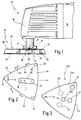
- the grinding device 10 shown in FIG. 1 has a housing 12 in which an electric motor drive is accommodated, whose rotary movement in a known manner via an oscillation drive in a back and forth swiveling movement of a drive axle 16 with a small swivel angle of the order of magnitude from about 0.5 to 7 ° and with a relatively high frequency is implemented, which is preferably greater than 5,000 vibrations / minute is, and possibly in a range between 10,000 and 25,000 vibrations / minute can be adjustable.
- the outer end of the drive shaft 16 is through a flange 18th widened on which a triangular grinding tool 22 by means of a recording designated as a whole with the number 25, which are outside the geometric center of the grinding tool 22 is located, can be attached.
- the Grinding tool 22 namely includes an overall number 24 designated grinding plate, on the drive axis 16 removed underside either immediately an abrasive can be applied, e.g. with diamond coated Sanding plates is the case.
- the bottom the grinding plate 24 also, as shown in the drawing, be provided with a Velcro material 32 so that on the Abrasive plate 24 an abrasive, so about a piece of sandpaper, the top of it with a suitable fabric material is provided, can be simply pressed open, so an easily detachable connection between a detachable abrasive and to enable the grinding plate 24.
- the grinding tool 22 therefore exists in the application case either from abrasive plate 24 with an abrasive coating the bottom or from grinding plate 24 and associated Abrasive that is releasable at the bottom of the sanding plate can be attached. It is understood that instead of one Connection option using a Velcro fastener, for example. also an adhesive connection with a removable adhesive tape into consideration can come.
- the grinding plate 24 has a flat aluminum carrier on its upper side 30 on an intermediate layer of plastic foam 28 is connected to the Velcro adhesive material 32, which is recorded on a suitable plastic layer.
- the grinding device according to the invention now differs from a grinder according to the prior art through the recording 25, which is shown in Figs. 1 and 2.
- the receptacle 25 has an elongated hole in this embodiment 26, which is from the geometric center I of the grinding plate 24 from an imaginary connecting line to the opposite Corner 42 towards the adjacent side edge 41 extends.
- a fastener can in the form of a screw 38 through a washer 36 with its thread 34 in a threaded blind hole 20 Drive shaft 16 are screwed.
- the mounting opening is designed as an elongated hole 26, so can the geometric location of the connection between grinding plate 24 and set the drive axis 16, that is, approximately from the geometric Center I from to one of the opposite If necessary, move corner 42 of the distant end position II the greatest possible deflection in the opposite corner area 42 and a stronger grinding effect in the middle area is desired, or in the direction of the opposite Move corner 42 to position III by about one less grinding effect in the area of the opposite corner 42 to achieve.
- the grinding tool 24a comprises a total of four Fastening openings, namely a centrally arranged fastening opening 26a and one towards the side edge 41 offset fastening opening 27, two further fastening openings 29, 31 are only optionally provided, such as can be clarified by the broken line in Fig. 3 should.
- the one off-center mounting opening In principle, 27 would be sufficient to take advantage of the invention to be able to use.
- the mounting opening 26a can be provided in the center, in addition to the off-center Arrangement also a central attachment of the grinding tool to allow on the drive shaft 16, if a particular vibration-free work necessary for certain applications is.
- additional mounting holes 29, 31, which are preferably each in a corresponding manner opposite corner are offset so that overall a symmetrical arrangement results in an exchange option to be created after wear of the grinding tool 22a in a corner area by twisting and fastening at another fastening opening the not yet completely used areas of the abrasive or polishing agent to be able to use.
- FIG. 3 there is also a fastening opening as another possibility 33 provided in the area of a corner.
- a fastening opening 33 as another possibility 33 provided in the area of a corner.
- the fixed drive shaft 16 with this fastening opening 33 connected there is a strong grinding effect in the area the opposite edge, e.g. is advantageous if must be worked along an inner longitudinal edge. It is understood that in this case, of course, no work more into a corner area is possible because the two the fastening opening 33 opposite corners no longer be pivoted at a small angle, but larger deflections with a back and forth movement along a Experience circular segment with respect to the mounting opening 33.
Landscapes
- Engineering & Computer Science (AREA)
- Mechanical Engineering (AREA)
- Polishing Bodies And Polishing Tools (AREA)
- Constituent Portions Of Griding Lathes, Driving, Sensing And Control (AREA)
- Finish Polishing, Edge Sharpening, And Grinding By Specific Grinding Devices (AREA)
Abstract
Description
- Fig. 1
- eine Seitenteilansicht eines erfindungsgemäßen Schleifgerätes im vorderen Bereich des Gehäuses mit der Antriebswelle und einem aufgesetzten Schleifwerkzeug in teilweise geschnittener Darstellung;
- Fig. 2
- eine Aufsicht auf das Schleifwerkzeug gemäß Fig. 1 von oben und
- Fig. 3
- eine Aufsicht einer alternativen Ausführungsform des Schleifwerkzeuges.
Claims (16)
- Schleifgerät mit einem oszillierenden Antrieb (14) zum oszillierenden Antrieb eines Schleifwerkzeuges (22, 22a) um eine gerätefeste Antriebsachse (16), wobei das Schleifwerkzeug (22, 22a) eine Schleifplatte (24, 24a) mit mindestens zwei vorzugsweise konvex nach außen gekrümmten Seitenkanten (40, 41, 43), die in zumindest einer Ecke (42, 52, 54) zusammenlaufen, aufweist, und wobei die Schleifplatte (24, 24a) eine Aufnahme (25, 25a) zur Befestigung an der Antriebsachse (16) aufweist, dadurch gekennzeichnet, daß die Aufnahme (25, 25a) an der Schleifplatte (24, 24a) außermittig angeordnet ist.
- Schleifgerät nach Anspruch 1, dadurch gekennzeichnet, daß die Schleifplatte (24) ein einstellbares Verbindungselement zur Befestigung der Schleifplatte (24) in verschiedenen Positionen an der Antriebsachse (16) aufweist.
- Schleifgerät nach Anspruch 2, dadurch gekennzeichnet, daß das Verbindungselement ein Langloch (26) umfaßt, durch das ein Befestigungselement (38) in verschiedenen Positionen mit der Antriebsachse (16) verbindbar ist.
- Schleifgerät nach Anspruch 1, dadurch gekennzeichnet, daß die Schleifplatte (24a) mindestens eine außermittig angeordnete Befestigungsöffnung (27, 29, 31) zur Aufnahme eines Befestigungselementes (38) aufweist.
- Schleifgerät nach Anspruch 4, dadurch gekennzeichnet, daß eine Mehrzahl von Befestigungöffnungen (26a, 27, 29, 31) an der Schleifplatte (24a) vorgesehen ist.
- Schleifgerät nach einem der vorhergehenden Ansprüche, dadurch gekennzeichnet, daß die Schleifplatte (24, 24a) dreieckförmig ausgebildet ist und konvex nach außen gekrümmte Seitenkanten (40, 41, 43) aufweist.
- Schleifgerät nach Anspruch 6, dadurch gekennzeichnet, daß die Aufnahme (25a) mindestens eine Befestigungsöffnung (27, 29, 31) aufweist, die vom Mittelpunkt (I) der Schleifplatte (24a) aus zu einer benachbarten Seitenkante (41) hin auf einer durch den Mittelpunkt (I) und eine gegenüberliegende Ecke (42) gelegten Verbindungslinie versetzt ist.
- Schleifgerät nach einem der vorhergehenden Ansprüche, dadurch gekennzeichnet, daß die Schleifplatte (24a) mindestens eine im Bereich einer Ecke angeordnete Befestigungsöffnung (33) aufweist.
- Schleifwerkzeug für ein Schleifgerät mit einem oszillierenden Antrieb (14) zum oszillierenden Antrieb einer Antriebsachse (16), wobei das Schleifwerkzeug (22, 22a) eine Schleifplatte (24, 24a) mit mindestens zwei vorzugsweise konvex nach außen gekrümmten Seitenkanten (40, 41, 43), die in zumindest einer Ecke (42, 52, 54) zusammenlaufen, aufweist, und wobei die Schleifplatte (24, 24a) eine Aufnahme (25, 25a) zur Befestigung an der Antriebsachse (16) aufweist, dadurch gekennzeichnet, daß die Aufnahme (25, 25a) an der Schleifplatte (24, 24a) außermittig angeordnet ist.
- Schleifwerkzeug nach Anspruch 9, dadurch gekennzeichnet, daß die Schleifplatte (24) ein einstellbares Verbindungselement zur Befestigung der Schleifplatte (24) in verschiedenen Positionen an der Antriebsachse (16) aufweist.
- Schleifwerkzeug nach Anspruch 10, dadurch gekennzeichnet, daß die Schleifplatte (24) von einem Langloch (26) durchsetzt ist.
- Schleifwerkzeug nach Anspruch 9, dadurch gekennzeichnet, daß die Schleifplatte (24a) mindestens eine außermittig angeordnete Befestigungsöffnung (27, 29, 31) zur Aufnahme eines Befestigungselementes (38) aufweist.
- Schleifwerkzeug nach Anspruch 12, dadurch gekennzeichnet, daß die Schleifplatte (24a) eine Mehrzahl von Befestigungsöffnungen aufweist (26a, 27, 29, 31).
- Schleifwerkzeug nach einem der Ansprüche 9-13, dadurch gekennzeichnet, daß die Schleifplatte (24, 24a) dreieckförmig ausgebildet ist und konvex nach außen gekrümmte Seitenkanten (40, 41, 43) aufweist.
- Schleifwerkzeug nach Anspruch 14, dadurch gekennzeichnet, daß die Aufnahme (25a) mindestens eine Befestigungsöffnung (27, 29, 31) aufweist, die vom Mittelpunkt (I) der Schleifplatte (24a) aus zu einer benachbarten Seitenkante (41) hin auf einer durch den Mittelpunkt (I) und eine gegenüberliegende Ecke (42) gelegten Verbindungslinie versetzt ist.
- Schleifwerkzeug nach einem der Ansprüche 9-15, dadurch gekennzeichnet, daß die Schleifplatte (24a) mindestens eine im Bereich einer Ecke angeordnete Befestigungsöffnung (33) aufweist.
Applications Claiming Priority (2)
| Application Number | Priority Date | Filing Date | Title |
|---|---|---|---|
| DE19809937A DE19809937A1 (de) | 1998-03-07 | 1998-03-07 | Schleifgerät |
| DE19809937 | 1998-03-07 |
Publications (3)
| Publication Number | Publication Date |
|---|---|
| EP0941804A2 true EP0941804A2 (de) | 1999-09-15 |
| EP0941804A3 EP0941804A3 (de) | 2001-07-11 |
| EP0941804B1 EP0941804B1 (de) | 2006-06-07 |
Family
ID=7860143
Family Applications (1)
| Application Number | Title | Priority Date | Filing Date |
|---|---|---|---|
| EP99102065A Expired - Lifetime EP0941804B1 (de) | 1998-03-07 | 1999-01-30 | Schleifgerät |
Country Status (3)
| Country | Link |
|---|---|
| US (1) | US6099397A (de) |
| EP (1) | EP0941804B1 (de) |
| DE (2) | DE19809937A1 (de) |
Families Citing this family (54)
| Publication number | Priority date | Publication date | Assignee | Title |
|---|---|---|---|---|
| ITPC20010018U1 (it) * | 2001-08-06 | 2003-02-06 | Tullio Arcobello | Utensile, in particolare settore diamantato per macchine e per la lucidatura di superfici quali agglomerati, piastrelle o simili. |
| US20030152737A1 (en) * | 2002-02-08 | 2003-08-14 | Shermer Jason C. | Universal abrasive sheet |
| US7188628B2 (en) * | 2002-02-27 | 2007-03-13 | Shubert Lawrence G | Fingernail trimmer having rotationally oscillating abrasive surface |
| DE60316144T2 (de) * | 2002-12-03 | 2007-12-13 | S.C. Johnson & Son, Inc., Racine | Motorisch angetriebenes reinigungs-/poliergerät |
| US7565712B2 (en) * | 2003-11-26 | 2009-07-28 | S.C. Johnson & Son, Inc. | Powered cleaner/polisher |
| JP4866569B2 (ja) * | 2005-05-27 | 2012-02-01 | 日東工器株式会社 | 研磨工具 |
| CA2529354A1 (en) * | 2005-12-08 | 2007-06-08 | Luigi Panfili | Sanding device, system including the same, and method of operating associated thereto |
| DE202006013890U1 (de) * | 2006-09-01 | 2006-11-16 | C. & E. Fein Gmbh | Werkzeugbefestigung |
| USD567053S1 (en) | 2006-09-26 | 2008-04-22 | A. Richard S.E.N.C. | Sanding device |
| US20080233845A1 (en) | 2007-03-21 | 2008-09-25 | 3M Innovative Properties Company | Abrasive articles, rotationally reciprocating tools, and methods |
| RU2009134876A (ru) | 2007-03-21 | 2011-04-27 | 3М Инновейтив Пропертиз Компани (3M Innovative Properties Company) (US) | Способы устранения дефектов поверхностей |
| US20100009607A1 (en) * | 2008-07-10 | 2010-01-14 | 3M Innovative Properties Company | Conversion assemblage adaptable for use in combination with a surface modifying apparatus and method thereof |
| US8469775B2 (en) * | 2008-07-10 | 2013-06-25 | 3M Innovative Properties Company | Conversion assemblage adaptable for use in combination with a surface modifying apparatus and method thereof |
| US20100009606A1 (en) * | 2008-07-10 | 2010-01-14 | 3M Innovative Properties Company | Conversion assemblage adaptable for use in combination with a surface modifying apparatus and method thereof |
| USD606827S1 (en) | 2009-06-18 | 2009-12-29 | 3M Innovative Properties Company | Small, portable power tool |
| USD610430S1 (en) | 2009-06-18 | 2010-02-23 | 3M Innovative Properties Company | Stem for a power tool attachment |
| USD619152S1 (en) | 2009-12-18 | 2010-07-06 | Techtronic Power Tools Technology Limited | Adapter |
| USD623034S1 (en) | 2009-12-18 | 2010-09-07 | Techtronic Power Tools Technology Limited | Tool arbor |
| US9073195B2 (en) | 2010-04-29 | 2015-07-07 | Black & Decker Inc. | Universal accessory for oscillating power tool |
| US8925931B2 (en) | 2010-04-29 | 2015-01-06 | Black & Decker Inc. | Oscillating tool |
| US9186770B2 (en) | 2010-04-29 | 2015-11-17 | Black & Decker Inc. | Oscillating tool attachment feature |
| USD651062S1 (en) | 2010-09-29 | 2011-12-27 | Milwaukee Electric Tool Corporation | Tool interface for an accessory |
| USD653523S1 (en) | 2010-09-29 | 2012-02-07 | Milwaukee Electric Tool Corporation | Adapter for a tool |
| USD646542S1 (en) | 2010-09-29 | 2011-10-11 | Milwaukee Electric Tool Corporation | Accessory interface for a tool |
| US9149923B2 (en) | 2010-11-09 | 2015-10-06 | Black & Decker Inc. | Oscillating tools and accessories |
| USD652274S1 (en) | 2010-12-14 | 2012-01-17 | Techtronic Power Tools Technology Limited | Universal interface for accessory blades |
| USD651874S1 (en) | 2010-12-14 | 2012-01-10 | Techtronic Power Tools Technology Limited | Universal interface for accessory blades |
| USD651876S1 (en) | 2010-12-14 | 2012-01-10 | Techtronic Power Tools Technology Limited | Universal interface for accessory blades |
| USD651875S1 (en) | 2010-12-14 | 2012-01-10 | Techtronic Power Tools Technology Limited | Universal interface for accessory blades |
| USD651878S1 (en) | 2010-12-14 | 2012-01-10 | Techtronic Power Tools Technology Limited | Universal interface for accessory blades |
| USD651877S1 (en) | 2010-12-14 | 2012-01-10 | Techtronic Power Tools Technology Limited | Universal interface for accessory blades |
| USD710669S1 (en) * | 2012-05-24 | 2014-08-12 | Sm Products Llc | Sanding pad |
| USD691013S1 (en) * | 2012-06-04 | 2013-10-08 | Sm Products, Llc | Sanding pad for reciprocating saw |
| USD694076S1 (en) | 2012-06-25 | 2013-11-26 | Techtronic Power Tools Technology Limited | Universal interface for accessory blades |
| USD694598S1 (en) | 2012-06-25 | 2013-12-03 | Techtronic Power Tools Technology Limited | Universal interface for accessory blades |
| USD694596S1 (en) | 2012-06-25 | 2013-12-03 | Techtronic Power Tools Technology Limited | Universal interface for accessory blades |
| USD694597S1 (en) | 2012-06-25 | 2013-12-03 | Techtronic Power Tools Technology Limited | Universal interface for accessory blades |
| USD694599S1 (en) | 2012-06-25 | 2013-12-03 | Techtronic Power Tools Technology Limited | Universal interface for accessory blades |
| USD734116S1 (en) * | 2012-06-27 | 2015-07-14 | Kwai Sun Oliver Wong | Replacement head for a hand-held sanding implement |
| USD832666S1 (en) | 2012-07-16 | 2018-11-06 | Black & Decker Inc. | Oscillating saw blade |
| US9555554B2 (en) | 2013-05-06 | 2017-01-31 | Milwaukee Electric Tool Corporation | Oscillating multi-tool system |
| CA2822631A1 (en) | 2013-08-01 | 2015-02-01 | A. Richard Tools Co./Outils A. Richard Co. | Sanding device, and sanding assembly including the same |
| US10252441B2 (en) | 2013-08-28 | 2019-04-09 | Corning Incorporated | System and method for cutting a wet green ceramic article |
| CN103909455A (zh) * | 2014-04-03 | 2014-07-09 | 芜湖新利德玻璃制品有限公司 | 打磨机 |
| JP6454850B2 (ja) * | 2014-10-21 | 2019-01-23 | 株式会社龍泉刃物 | 振動型刃物研磨器及びこれを用いた刃物の研磨方法 |
| USD814900S1 (en) | 2017-01-16 | 2018-04-10 | Black & Decker Inc. | Blade for oscillating power tools |
| US10265778B2 (en) | 2017-01-16 | 2019-04-23 | Black & Decker Inc. | Accessories for oscillating power tools |
| USD925318S1 (en) * | 2019-02-28 | 2021-07-20 | Guido Valentini | Delta shaped backing pad with dove-tail |
| USD951739S1 (en) * | 2019-04-18 | 2022-05-17 | Mirka Ltd | Backing pad for sander |
| USD952432S1 (en) * | 2020-10-23 | 2022-05-24 | Jing Men Jun Kai E-commerce Co., Ltd. | Polishing pad |
| USD952431S1 (en) * | 2020-10-23 | 2022-05-24 | Jing Men Jun Kai E-commerce Co., Ltd. | Polishing pad |
| USD968186S1 (en) * | 2020-11-09 | 2022-11-01 | Lake Country Tool, Llc | Polishing pad |
| USD980032S1 (en) * | 2022-08-23 | 2023-03-07 | Jiangzhao Liu | Polishing pad |
| US20240164791A1 (en) * | 2022-11-18 | 2024-05-23 | Insurgical, Inc. | Medical tool with vibration damping |
Family Cites Families (7)
| Publication number | Priority date | Publication date | Assignee | Title |
|---|---|---|---|---|
| EP0244465B1 (de) * | 1985-11-15 | 1989-08-02 | C. & E. FEIN GmbH & Co. | Handschleifgerät |
| DE4314799C2 (de) * | 1993-05-05 | 1995-04-13 | Fein C & E | Elektrowerkzeug |
| GB9313610D0 (en) * | 1993-07-01 | 1993-08-18 | Black & Decker Inc | Two plane oscillating sander |
| US5491896A (en) * | 1993-12-17 | 1996-02-20 | Ryobi Motor Products | Attachment and accessory scraper blades for detail sander |
| US5470272A (en) * | 1994-02-03 | 1995-11-28 | Ryobi Motor Products Corp. | Removable working tool assembly |
| DE9410754U1 (de) * | 1994-07-05 | 1994-09-22 | C. & E. Fein GmbH & Co KG, 70176 Stuttgart | Schleifwerkzeug für ein Handschleifgerät |
| DE29501951U1 (de) * | 1995-02-07 | 1995-03-16 | Henning, Wilhelm, Dr., 45525 Hattingen | Halterung zum Anbringen von Zusatzgeräten an Schwingschleifern |
-
1998
- 1998-03-07 DE DE19809937A patent/DE19809937A1/de not_active Ceased
-
1999
- 1999-01-30 DE DE59913497T patent/DE59913497D1/de not_active Expired - Lifetime
- 1999-01-30 EP EP99102065A patent/EP0941804B1/de not_active Expired - Lifetime
- 1999-03-05 US US09/263,604 patent/US6099397A/en not_active Expired - Lifetime
Also Published As
| Publication number | Publication date |
|---|---|
| DE59913497D1 (de) | 2006-07-20 |
| DE19809937A1 (de) | 1999-09-09 |
| EP0941804A3 (de) | 2001-07-11 |
| US6099397A (en) | 2000-08-08 |
| EP0941804B1 (de) | 2006-06-07 |
Similar Documents
| Publication | Publication Date | Title |
|---|---|---|
| EP0941804A2 (de) | Schleifgerät | |
| EP0424720B1 (de) | Vorsatzgerät für einen Winkelschleifer | |
| DE4314799C2 (de) | Elektrowerkzeug | |
| EP0710527B1 (de) | Handwerkzeugmaschine zur Flächenbearbeitung | |
| DE69601684T2 (de) | Schmirgelmaschine | |
| DE60101652T2 (de) | Schleifwerkzeug | |
| DE4444028A1 (de) | Vorrichtung und zusätzliche Schleifscheiben für Detailschleifgeräte | |
| WO1987002924A1 (fr) | Meuleuse portative | |
| WO2002053321A1 (de) | Handwerkzeugmaschine | |
| EP0610801B1 (de) | Handwerkzeugmaschine zur Flächenbearbeitung | |
| DE3805926A1 (de) | Handaggregat mit oszillierender werkzeugbewegung | |
| DE4118392B4 (de) | Exzenterschleifer | |
| DE69506474T2 (de) | Vorrichtung zum Planen oder Polieren von steinigen Materialen | |
| DE3884187T2 (de) | Sandpapierschleifgerät. | |
| DE10200381A1 (de) | Vorrichtung zur Bearbeitung von Oberflächen | |
| DE19914956C2 (de) | Elektromotorisch antreibbares Schleifgerät | |
| DE3685864T2 (de) | Einspannvorrichtung zum schleifen von messern. | |
| DE9410754U1 (de) | Schleifwerkzeug für ein Handschleifgerät | |
| DE3706906A1 (de) | Schleifkoerper fuer motorgetriebene schleifapparate | |
| DE19617474A1 (de) | Schwingschleifer | |
| DE19723987A1 (de) | Schleifwerkzeug, insbesondere für Hand-Oszillationsgeräte | |
| DE2332454A1 (de) | Positionierungsvorrichtung fuer ein maschinenwerkzeug | |
| DE9320393U1 (de) | Handwerkzeugmaschine zur Flächenbearbeitung | |
| DE4432974B4 (de) | Handgeführter, elektrischer Bandschleifer | |
| DE69607194T2 (de) | Drahtbürsteneinheit für winkelschleifer |
Legal Events
| Date | Code | Title | Description |
|---|---|---|---|
| PUAI | Public reference made under article 153(3) epc to a published international application that has entered the european phase |
Free format text: ORIGINAL CODE: 0009012 |
|
| AK | Designated contracting states |
Kind code of ref document: A2 Designated state(s): CH DE FR GB IT LI NL |
|
| AX | Request for extension of the european patent |
Free format text: AL;LT;LV;MK;RO;SI |
|
| RAP1 | Party data changed (applicant data changed or rights of an application transferred) |
Owner name: C. & E. FEIN GMBH & CO. KG |
|
| PUAL | Search report despatched |
Free format text: ORIGINAL CODE: 0009013 |
|
| AK | Designated contracting states |
Kind code of ref document: A3 Designated state(s): AT BE CH CY DE DK ES FI FR GB GR IE IT LI LU MC NL PT SE |
|
| AX | Request for extension of the european patent |
Free format text: AL;LT;LV;MK;RO;SI |
|
| 17P | Request for examination filed |
Effective date: 20011219 |
|
| AKX | Designation fees paid |
Free format text: CH DE FR GB IT LI NL |
|
| RAP1 | Party data changed (applicant data changed or rights of an application transferred) |
Owner name: C. & E. FEIN GMBH |
|
| 17Q | First examination report despatched |
Effective date: 20040701 |
|
| RAP1 | Party data changed (applicant data changed or rights of an application transferred) |
Owner name: C. & E. FEIN GMBH |
|
| GRAP | Despatch of communication of intention to grant a patent |
Free format text: ORIGINAL CODE: EPIDOSNIGR1 |
|
| GRAS | Grant fee paid |
Free format text: ORIGINAL CODE: EPIDOSNIGR3 |
|
| GRAA | (expected) grant |
Free format text: ORIGINAL CODE: 0009210 |
|
| AK | Designated contracting states |
Kind code of ref document: B1 Designated state(s): CH DE FR GB IT LI NL |
|
| PG25 | Lapsed in a contracting state [announced via postgrant information from national office to epo] |
Ref country code: IT Free format text: LAPSE BECAUSE OF FAILURE TO SUBMIT A TRANSLATION OF THE DESCRIPTION OR TO PAY THE FEE WITHIN THE PRE;WARNING: LAPSES OF ITALIAN PATENTS WITH EFFECTIVE DATE BEFORE 2007 MAY HAVE OCCURRED AT ANY TIME BEFORE 2007. THE CORRECT EFFECTIVE DATE MAY BE DIFFERENT FROM THE ONE RECORDED.SCRIBED TIME-LIMIT Effective date: 20060607 |
|
| REG | Reference to a national code |
Ref country code: GB Ref legal event code: FG4D Free format text: NOT ENGLISH |
|
| RAP4 | Party data changed (patent owner data changed or rights of a patent transferred) |
Owner name: C. & E. FEIN GMBH |
|
| REG | Reference to a national code |
Ref country code: CH Ref legal event code: NV Representative=s name: TROESCH SCHEIDEGGER WERNER AG Ref country code: CH Ref legal event code: EP |
|
| REF | Corresponds to: |
Ref document number: 59913497 Country of ref document: DE Date of ref document: 20060720 Kind code of ref document: P |
|
| GBT | Gb: translation of ep patent filed (gb section 77(6)(a)/1977) |
Effective date: 20060908 |
|
| ET | Fr: translation filed | ||
| PLBE | No opposition filed within time limit |
Free format text: ORIGINAL CODE: 0009261 |
|
| STAA | Information on the status of an ep patent application or granted ep patent |
Free format text: STATUS: NO OPPOSITION FILED WITHIN TIME LIMIT |
|
| 26N | No opposition filed |
Effective date: 20070308 |
|
| PGFP | Annual fee paid to national office [announced via postgrant information from national office to epo] |
Ref country code: IT Payment date: 20120117 Year of fee payment: 14 |
|
| PGFP | Annual fee paid to national office [announced via postgrant information from national office to epo] |
Ref country code: CH Payment date: 20130114 Year of fee payment: 15 Ref country code: FR Payment date: 20130204 Year of fee payment: 15 Ref country code: GB Payment date: 20130130 Year of fee payment: 15 |
|
| PGFP | Annual fee paid to national office [announced via postgrant information from national office to epo] |
Ref country code: NL Payment date: 20130110 Year of fee payment: 15 |
|
| REG | Reference to a national code |
Ref country code: NL Ref legal event code: V1 Effective date: 20140801 |
|
| REG | Reference to a national code |
Ref country code: CH Ref legal event code: PL |
|
| GBPC | Gb: european patent ceased through non-payment of renewal fee |
Effective date: 20140130 |
|
| PG25 | Lapsed in a contracting state [announced via postgrant information from national office to epo] |
Ref country code: NL Free format text: LAPSE BECAUSE OF NON-PAYMENT OF DUE FEES Effective date: 20140801 Ref country code: CH Free format text: LAPSE BECAUSE OF NON-PAYMENT OF DUE FEES Effective date: 20140131 Ref country code: LI Free format text: LAPSE BECAUSE OF NON-PAYMENT OF DUE FEES Effective date: 20140131 |
|
| REG | Reference to a national code |
Ref country code: FR Ref legal event code: ST Effective date: 20140930 |
|
| PG25 | Lapsed in a contracting state [announced via postgrant information from national office to epo] |
Ref country code: FR Free format text: LAPSE BECAUSE OF NON-PAYMENT OF DUE FEES Effective date: 20140131 Ref country code: GB Free format text: LAPSE BECAUSE OF NON-PAYMENT OF DUE FEES Effective date: 20140130 |
|
| PGFP | Annual fee paid to national office [announced via postgrant information from national office to epo] |
Ref country code: DE Payment date: 20150127 Year of fee payment: 17 |
|
| PG25 | Lapsed in a contracting state [announced via postgrant information from national office to epo] |
Ref country code: IT Free format text: LAPSE BECAUSE OF NON-PAYMENT OF DUE FEES Effective date: 20140130 |
|
| REG | Reference to a national code |
Ref country code: DE Ref legal event code: R119 Ref document number: 59913497 Country of ref document: DE |
|
| PG25 | Lapsed in a contracting state [announced via postgrant information from national office to epo] |
Ref country code: DE Free format text: LAPSE BECAUSE OF NON-PAYMENT OF DUE FEES Effective date: 20160802 |