EP0942108B1 - Elément modulaire et encadrement - Google Patents
Elément modulaire et encadrement Download PDFInfo
- Publication number
- EP0942108B1 EP0942108B1 EP99890087A EP99890087A EP0942108B1 EP 0942108 B1 EP0942108 B1 EP 0942108B1 EP 99890087 A EP99890087 A EP 99890087A EP 99890087 A EP99890087 A EP 99890087A EP 0942108 B1 EP0942108 B1 EP 0942108B1
- Authority
- EP
- European Patent Office
- Prior art keywords
- frame
- connection
- suchlike
- surrounding
- modular
- Prior art date
- Legal status (The legal status is an assumption and is not a legal conclusion. Google has not performed a legal analysis and makes no representation as to the accuracy of the status listed.)
- Expired - Lifetime
Links
- 239000000463 material Substances 0.000 claims description 33
- 125000006850 spacer group Chemical group 0.000 claims description 19
- 238000010276 construction Methods 0.000 claims description 17
- 239000004575 stone Substances 0.000 claims description 14
- 238000010438 heat treatment Methods 0.000 claims description 13
- 239000004567 concrete Substances 0.000 claims description 11
- 238000013461 design Methods 0.000 claims description 8
- 230000015572 biosynthetic process Effects 0.000 claims description 7
- 230000000087 stabilizing effect Effects 0.000 claims description 7
- 238000003466 welding Methods 0.000 claims description 7
- 239000000853 adhesive Substances 0.000 claims description 5
- 238000003860 storage Methods 0.000 claims description 5
- 238000012546 transfer Methods 0.000 claims description 5
- 239000002023 wood Substances 0.000 claims description 5
- 230000001070 adhesive effect Effects 0.000 claims description 4
- 238000000465 moulding Methods 0.000 claims description 4
- 210000000056 organ Anatomy 0.000 claims description 4
- 239000011230 binding agent Substances 0.000 claims description 3
- 239000004744 fabric Substances 0.000 claims description 3
- 238000003780 insertion Methods 0.000 claims description 3
- 230000037431 insertion Effects 0.000 claims description 3
- 239000007769 metal material Substances 0.000 claims description 3
- 239000002969 artificial stone Substances 0.000 claims description 2
- 239000011810 insulating material Substances 0.000 claims description 2
- 239000011505 plaster Substances 0.000 claims description 2
- 239000002344 surface layer Substances 0.000 claims 7
- 229920002994 synthetic fiber Polymers 0.000 claims 3
- 241000196324 Embryophyta Species 0.000 claims 2
- 229910000831 Steel Inorganic materials 0.000 claims 2
- 239000010959 steel Substances 0.000 claims 2
- QNRATNLHPGXHMA-XZHTYLCXSA-N (r)-(6-ethoxyquinolin-4-yl)-[(2s,4s,5r)-5-ethyl-1-azabicyclo[2.2.2]octan-2-yl]methanol;hydrochloride Chemical compound Cl.C([C@H]([C@H](C1)CC)C2)CN1[C@@H]2[C@H](O)C1=CC=NC2=CC=C(OCC)C=C21 QNRATNLHPGXHMA-XZHTYLCXSA-N 0.000 claims 1
- 235000008733 Citrus aurantifolia Nutrition 0.000 claims 1
- 235000013162 Cocos nucifera Nutrition 0.000 claims 1
- 244000060011 Cocos nucifera Species 0.000 claims 1
- 235000011777 Corchorus aestuans Nutrition 0.000 claims 1
- 240000000491 Corchorus aestuans Species 0.000 claims 1
- 235000010862 Corchorus capsularis Nutrition 0.000 claims 1
- 235000011941 Tilia x europaea Nutrition 0.000 claims 1
- 239000004411 aluminium Substances 0.000 claims 1
- 229910052782 aluminium Inorganic materials 0.000 claims 1
- XAGFODPZIPBFFR-UHFFFAOYSA-N aluminium Chemical compound [Al] XAGFODPZIPBFFR-UHFFFAOYSA-N 0.000 claims 1
- 239000000835 fiber Substances 0.000 claims 1
- 238000009408 flooring Methods 0.000 claims 1
- 229910052500 inorganic mineral Inorganic materials 0.000 claims 1
- 239000010410 layer Substances 0.000 claims 1
- 239000004571 lime Substances 0.000 claims 1
- 239000004579 marble Substances 0.000 claims 1
- 239000002184 metal Substances 0.000 claims 1
- 229910052751 metal Inorganic materials 0.000 claims 1
- 239000011707 mineral Substances 0.000 claims 1
- 239000011490 mineral wool Substances 0.000 claims 1
- 239000011087 paperboard Substances 0.000 claims 1
- 239000002984 plastic foam Substances 0.000 claims 1
- 239000010454 slate Substances 0.000 claims 1
- 239000004753 textile Substances 0.000 claims 1
- 238000000034 method Methods 0.000 description 12
- 239000003381 stabilizer Substances 0.000 description 9
- 230000008569 process Effects 0.000 description 8
- 210000002414 leg Anatomy 0.000 description 7
- 238000004519 manufacturing process Methods 0.000 description 7
- 238000005516 engineering process Methods 0.000 description 5
- 238000004026 adhesive bonding Methods 0.000 description 4
- 238000004873 anchoring Methods 0.000 description 4
- 239000004927 clay Substances 0.000 description 4
- 239000002131 composite material Substances 0.000 description 4
- 230000002349 favourable effect Effects 0.000 description 4
- 239000004033 plastic Substances 0.000 description 4
- 230000008901 benefit Effects 0.000 description 3
- 239000000725 suspension Substances 0.000 description 3
- 238000012549 training Methods 0.000 description 3
- 150000001875 compounds Chemical class 0.000 description 2
- 230000008878 coupling Effects 0.000 description 2
- 238000010168 coupling process Methods 0.000 description 2
- 238000005859 coupling reaction Methods 0.000 description 2
- 238000010586 diagram Methods 0.000 description 2
- 239000013529 heat transfer fluid Substances 0.000 description 2
- 238000009413 insulation Methods 0.000 description 2
- 238000005192 partition Methods 0.000 description 2
- 230000002093 peripheral effect Effects 0.000 description 2
- 238000004804 winding Methods 0.000 description 2
- 235000014676 Phragmites communis Nutrition 0.000 description 1
- 238000010521 absorption reaction Methods 0.000 description 1
- 230000004308 accommodation Effects 0.000 description 1
- 230000001154 acute effect Effects 0.000 description 1
- 238000005054 agglomeration Methods 0.000 description 1
- 230000002776 aggregation Effects 0.000 description 1
- 230000009286 beneficial effect Effects 0.000 description 1
- 230000005540 biological transmission Effects 0.000 description 1
- 239000000919 ceramic Substances 0.000 description 1
- 238000004891 communication Methods 0.000 description 1
- 230000005574 cross-species transmission Effects 0.000 description 1
- 238000007688 edging Methods 0.000 description 1
- 230000000694 effects Effects 0.000 description 1
- 239000012530 fluid Substances 0.000 description 1
- 238000009432 framing Methods 0.000 description 1
- 239000011521 glass Substances 0.000 description 1
- 230000017525 heat dissipation Effects 0.000 description 1
- 238000009434 installation Methods 0.000 description 1
- 230000010354 integration Effects 0.000 description 1
- 238000005304 joining Methods 0.000 description 1
- 239000007788 liquid Substances 0.000 description 1
- 230000014759 maintenance of location Effects 0.000 description 1
- 239000002557 mineral fiber Substances 0.000 description 1
- 239000000203 mixture Substances 0.000 description 1
- 230000008520 organization Effects 0.000 description 1
- 230000036316 preload Effects 0.000 description 1
- 230000001105 regulatory effect Effects 0.000 description 1
- 230000029058 respiratory gaseous exchange Effects 0.000 description 1
- 238000000926 separation method Methods 0.000 description 1
- 238000005476 soldering Methods 0.000 description 1
- 239000011343 solid material Substances 0.000 description 1
- 230000006641 stabilisation Effects 0.000 description 1
- 238000011105 stabilization Methods 0.000 description 1
- 239000003351 stiffener Substances 0.000 description 1
- 238000005728 strengthening Methods 0.000 description 1
- 239000000126 substance Substances 0.000 description 1
- 210000000689 upper leg Anatomy 0.000 description 1
Images


Classifications
-
- E—FIXED CONSTRUCTIONS
- E04—BUILDING
- E04B—GENERAL BUILDING CONSTRUCTIONS; WALLS, e.g. PARTITIONS; ROOFS; FLOORS; CEILINGS; INSULATION OR OTHER PROTECTION OF BUILDINGS
- E04B9/00—Ceilings; Construction of ceilings, e.g. false ceilings; Ceiling construction with regard to insulation
- E04B9/04—Ceilings; Construction of ceilings, e.g. false ceilings; Ceiling construction with regard to insulation comprising slabs, panels, sheets or the like
- E04B9/0428—Ceilings; Construction of ceilings, e.g. false ceilings; Ceiling construction with regard to insulation comprising slabs, panels, sheets or the like having a closed frame around the periphery
-
- E—FIXED CONSTRUCTIONS
- E04—BUILDING
- E04B—GENERAL BUILDING CONSTRUCTIONS; WALLS, e.g. PARTITIONS; ROOFS; FLOORS; CEILINGS; INSULATION OR OTHER PROTECTION OF BUILDINGS
- E04B9/00—Ceilings; Construction of ceilings, e.g. false ceilings; Ceiling construction with regard to insulation
- E04B9/001—Ceilings; Construction of ceilings, e.g. false ceilings; Ceiling construction with regard to insulation characterised by provisions for heat or sound insulation
-
- E—FIXED CONSTRUCTIONS
- E04—BUILDING
- E04B—GENERAL BUILDING CONSTRUCTIONS; WALLS, e.g. PARTITIONS; ROOFS; FLOORS; CEILINGS; INSULATION OR OTHER PROTECTION OF BUILDINGS
- E04B9/00—Ceilings; Construction of ceilings, e.g. false ceilings; Ceiling construction with regard to insulation
- E04B9/04—Ceilings; Construction of ceilings, e.g. false ceilings; Ceiling construction with regard to insulation comprising slabs, panels, sheets or the like
- E04B9/0435—Ceilings; Construction of ceilings, e.g. false ceilings; Ceiling construction with regard to insulation comprising slabs, panels, sheets or the like having connection means at the edges
-
- E—FIXED CONSTRUCTIONS
- E04—BUILDING
- E04B—GENERAL BUILDING CONSTRUCTIONS; WALLS, e.g. PARTITIONS; ROOFS; FLOORS; CEILINGS; INSULATION OR OTHER PROTECTION OF BUILDINGS
- E04B9/00—Ceilings; Construction of ceilings, e.g. false ceilings; Ceiling construction with regard to insulation
- E04B9/04—Ceilings; Construction of ceilings, e.g. false ceilings; Ceiling construction with regard to insulation comprising slabs, panels, sheets or the like
- E04B9/045—Ceilings; Construction of ceilings, e.g. false ceilings; Ceiling construction with regard to insulation comprising slabs, panels, sheets or the like being laminated
-
- E—FIXED CONSTRUCTIONS
- E04—BUILDING
- E04B—GENERAL BUILDING CONSTRUCTIONS; WALLS, e.g. PARTITIONS; ROOFS; FLOORS; CEILINGS; INSULATION OR OTHER PROTECTION OF BUILDINGS
- E04B9/00—Ceilings; Construction of ceilings, e.g. false ceilings; Ceiling construction with regard to insulation
- E04B9/22—Connection of slabs, panels, sheets or the like to the supporting construction
- E04B9/28—Connection of slabs, panels, sheets or the like to the supporting construction with the slabs, panels, sheets or the like having grooves engaging with horizontal flanges of the supporting construction or accessory means connected thereto
-
- E—FIXED CONSTRUCTIONS
- E04—BUILDING
- E04C—STRUCTURAL ELEMENTS; BUILDING MATERIALS
- E04C2/00—Building elements of relatively thin form for the construction of parts of buildings, e.g. sheet materials, slabs, or panels
- E04C2/30—Building elements of relatively thin form for the construction of parts of buildings, e.g. sheet materials, slabs, or panels characterised by the shape or structure
- E04C2/38—Building elements of relatively thin form for the construction of parts of buildings, e.g. sheet materials, slabs, or panels characterised by the shape or structure with attached ribs, flanges, or the like, e.g. framed panels
- E04C2/384—Building elements of relatively thin form for the construction of parts of buildings, e.g. sheet materials, slabs, or panels characterised by the shape or structure with attached ribs, flanges, or the like, e.g. framed panels with a metal frame
-
- E—FIXED CONSTRUCTIONS
- E04—BUILDING
- E04F—FINISHING WORK ON BUILDINGS, e.g. STAIRS, FLOORS
- E04F13/00—Coverings or linings, e.g. for walls or ceilings
- E04F13/07—Coverings or linings, e.g. for walls or ceilings composed of covering or lining elements; Sub-structures therefor; Fastening means therefor
- E04F13/08—Coverings or linings, e.g. for walls or ceilings composed of covering or lining elements; Sub-structures therefor; Fastening means therefor composed of a plurality of similar covering or lining elements
- E04F13/0801—Separate fastening elements
- E04F13/0832—Separate fastening elements without load-supporting elongated furring elements between wall and covering elements
- E04F13/0833—Separate fastening elements without load-supporting elongated furring elements between wall and covering elements not adjustable
- E04F13/0846—Separate fastening elements without load-supporting elongated furring elements between wall and covering elements not adjustable the fastening elements engaging holes or grooves in the side faces of the covering elements
-
- E—FIXED CONSTRUCTIONS
- E04—BUILDING
- E04F—FINISHING WORK ON BUILDINGS, e.g. STAIRS, FLOORS
- E04F15/00—Flooring
- E04F15/02—Flooring or floor layers composed of a number of similar elements
Definitions
- the invention relates to a new modular table, wall, floor or Ceiling element with at least one surface or plate or insert element enclosing frame, with which it is connected to at least one further, another same or different type of surface element enclosing frame attachable and the same to a composite, essentially flat or also to one spatial structure is connectable.
- the interconnected module elements can be the same as each other Have functional tasks, e.g. or the like only as a room divider. serve e.g. as a base for Objects to be presented or the like serve. However, module elements can also be used specific functional tasks assembled into a multifunctional overall system become.
- Module elements are not on those extremely three-dimensional module elements and those that can be assembled from them three-dimensional overall systems, but mainly deals with as Module elements to be called "two-dimensional", of course at least with their material thickness, profile thickness or the like, extend into the third dimension.
- the aforementioned DE-A1 is very specifically aimed at modules for the model railway sector and further on essentially horizontal arrangement of the module elements to larger ones Underlay systems for model plants limited.
- model building or model landscape modules is the DE 29 20 971 A1 directed, the individual landscape modules in solid material without Enclosure frames are formed.
- the side flanks of the square modules there have all-round grooves for the longitudinal insertion of support rods, one Support rod is housed in the grooves of two modules lying side by side.
- the frame strips can also be constructed in several parts and the two the groove accompanying fanlken, which after assembly of the modules to larger areas According to a first design, units adjoin one another and end on both sides with a free one Edge, usually in the plane of the fillings carried by the individual frames various types and functions.
- the other type of framing profile does not end with free on both sides Flank edges, but with them are on both sides towards the module filling inwards angled wrap-around extensions arranged, which e.g. the fringes of the Spread over the filling.
- the lateral grooves are, as always, the Enclosure frames are designed in detail for reception and accommodation of connecting elements, bodies, clips, springs or the like. for a side-by-side or another connection between the modules is provided.
- connection elements mentioned for the frame modules described or also generally concerns first be a series of Cross-sectional shapes of tongue and groove cooperating connecting bodies of DE 809.865 describing apparatus parts and further to DE 35 42 830 A1 and Patent Abstract JAP M 1672, September 13, 1994, Vol. 18, No. 49.
- modules according to FR 1,084.219 A which ones an enclosure frame made of one-piece, miter-welded together Profiled strips with all-round groove and concrete filling on the object GB 1,285,603 A, whose profile strips forming the module frame are also in the module filling protruding anchoring projections are formed as well as the at least two among themselves e.g. module enclosing frame formed by welding longitudinally connected part profiles according to GB 1,132,774 A. With all those disclosed in these documents Modules have the enclosing frame on both sides - possible fillings or overlapping - inward angled marginal processes.
- the invention has set itself the task of being simple manufacturing, practically based on a single or only a few basic elements
- To create system which is an assembly to table, wall, floor and All kinds of ceiling structures.
- horizontal structures with various functions such as those with floor, table and Underlay functions, ceiling structures, and further from the two-dimensional structures imageable three-dimensional structures, e.g. Room dividers, conservatories, showcases, furniture and the like, as well as storage and storage systems and of course also modular elements for easily expandable model systems, storage and organization systems, such as. Toolbox systems or the like.
- the invention has the object of the disadvantages of the previous known embodiments of modules or, in particular, of their enclosing frames to avoid and to create such modules, the framework of which the required Ensure mechanical strength and rigidity on the one hand and which on the other hand Equipment of the previously closed, i.e. finished frames with the respective Allow filling where it is no longer necessary, first in an unfinished, so still to bring in the frame, the closed filling or the like. and only then finally to close the module frame.
- the Enclosure framework is only one type of basic profile that is intended for education provided basic profiles of the enclosing frame favorably equally permanently this edge edging by screwing, gluing or the like. and preferably by Welding or the like ready to be joined, and that finally to a side-by-side bond to allow two modular elements over their frames without space, the open to the outside, but in relation to those to the above, in one Geometric level aligned side-lying flanks towards the inside of the frame recessed, all-round groove, gutter, recess or the like, is provided.
- This Nut zone is in combination or cooperation with corresponding, usable in it Connection body for a lateral or other type of connection of the individual modular elements to an overall construction, e.g. a wall or Intermediate wall construction, to a showcase, to a horizontally extending structure, to a ceiling, a floor, an extensive table or presentation area or the like, suitable, as in the case of the connecting elements mentioned in the end are trained.
- an overall construction e.g. a wall or Intermediate wall construction
- a showcase to a horizontally extending structure
- a ceiling, a floor, an extensive table or presentation area or the like suitable, as in the case of the connecting elements mentioned in the end are trained.
- the profile shape essential to the invention is cheap, in which the - in principle with the two aligned flanks and the one in between recessed groove existing - molding profile of the enclosing frame of the new modular element due to an inward edge extension on only one of the both side contact flanks is supplemented.
- an edge can also in addition to be useful to prevent the surface element from falling out of the Prevent enclosing frame in any position.
- This can e.g. then be beneficial if from the frame, e.g. between the recessed, circumferential groove recess or from their a groove wall and the above-mentioned, also peripheral peripheral process the surface element e.g. a board, insulation board, plasterboard, glass or Mirror plate and the like arranged and also fixed in by means of the marginal process desired position should be held.
- the enclosing frame is or are - advantageously centrically or symmetrically - and advantageously identical in all, mostly Four, frame strips each have a through opening or several such through openings for energy supply and / or control lines or for connecting lines, couplings or the like, for example to the heating resistors, heating pipes or the like. provided as expressed in claim 2.
- the frame is a plate made of a hardened binder, for example a concrete plate, a torsion-resistant wood-based panel or the like. details of the design, as described above, are not as important.
- Claim 4 provides information about inexpensive ways of forming the connection of the individual strips of the enclosing frames via the corner miter to the finished frame of the modular elements according to the invention and about the mechanical stability achievable in this way, for example also against torsion.
- the miter connecting plate mentioned there can be in any way shaped, e.g. in the manner of a right-angled triangle or as an elbow with two Thighs or the like However, it is favorable if they each place one in the inside corner of the Enclosing frame has a suitable angle on one side and is furthermore so large that a mechanically stable connection of the frame profile strips in the corner areas of the Frame, preferably including at least one of the side walls of the inside recessed longitudinal groove or longitudinal recess is made possible.
- the one in claim 4 called two-leg stabilizer body is advantageously designed so that it with his Outer surfaces on the inner surfaces of the floors of the longitudinal recesses of the corner abutting strips of the containment frame is bound.
- This stabilizer body which is preferably designed as a square tubular profile piece for the frame of the new modular element can be used alone or together with the previous one be mentioned miter connecting plate.
- this plate e.g. connected by welding.
- the stabilizer body brings a high, additional mechanical strengthening of the Module frame and thus the modular element itself, especially against warpage and Torsion, which is particularly advantageous for larger wall structures.
- it can also be a very advantageous component for the attachment of Serve functional elements of all kinds from the suspension to a mainstay.
- the "filling" of the Enclosing frame e.g. a plate connected to the frame strips or e.g. a concrete slab as a “filling”, the function of all four miter connecting plates, angles or the like. can take over in one if this filling has a high rigidity.
- the miter connecting body or plates and the stabilizer body can also be designed, designed or equipped in any way, they are preferred e.g. through connection elements or organs for a connection with functional elements, such as legs, spacers, screws, eyelets or rings for one Threading of flexible elements such as hanging or support ropes or chains, Hooking elements, clamps etc., completed, as also explained in claim 5.
- functional elements such as legs, spacers, screws, eyelets or rings for one Threading of flexible elements such as hanging or support ropes or chains, Hooking elements, clamps etc., completed, as also explained in claim 5.
- Another possibility of mechanically stabilizing the enclosing frame of the modular element in conjunction with an integration of functional elements, such as suspensions, cantilever arms, legs or the like, consists in the arrangement of, preferably glued, in the inside corner areas of the frame.
- Claim 7 names some simple and therefore also inexpensive manufacture of the frame molding for the new modular elements, advantageous cross-sectional shapes .
- the longitudinal recesses of the enclosing frame strips with the cross-sectional shapes mentioned there have the advantage that if the enclosing frame of two modular elements by means of at least one - correspondingly shaped cross-section and corresponding shape - connecting body or profile to be joined together in a connection-locking manner, for example when higher, laterally acting forces occur, slipping out of the module assembly and thus an unintended, undesired separation of the modular elements from one another cannot occur.
- Claim 8 mentions particularly preferred sections or zones of the profiles which form the frame strips of the enclosing frame and which can advantageously be used for binding the surface elements or frame fillings.
- a second is for storage systems with a high degree of clarity and order function
- Form of training according to this claim is advantageous, which is the "filling" of the Enclosure frame forming surface elements in the manner of troughs or shops with or without subdivision, possibly in the form of the objects to be kept appropriate fit or with suitable brackets, e.g. B. brackets or the like.
- fourth Design of the modular element according to the invention is particularly suitable for Formation of floors, exposed walls and also ceilings, with this type of module elements also the aesthetic aspect is not neglected.
- a modular element of the fifth type within the scope of the invention the in addition to its function as a "stone" for a floor covering or as a plate for a partition or the like. is able to perform another technical function.
- Such a modular element there is also the function of an energy exchanger, specifically the Heat dissipation, whereby both electrical energy and heat transfer fluids as Energy sources come into question.
- Multi-layer structure of the surface element surrounded by the enclosing frame e.g. in the case of a floor heating stone with an upper step plate, e.g.
- radiator plate made of stone, artificial stone, Ceramics or the like, one below, that is, inside, arranged radiator plate with a Energy delivery device, with a e.g. Resistance wires or heat transfer fluid pipes, enclosing, preferably having heat transfer properties, Embedding compound and a thermal and impact sound insulation that forms the bottom.
- a Energy delivery device with a e.g. Resistance wires or heat transfer fluid pipes, enclosing, preferably having heat transfer properties, Embedding compound and a thermal and impact sound insulation that forms the bottom.
- Preferred materials for the step-like or face-side plate-like surface element favorably less porous stone material, are mentioned in claim 10, whereby a structure of the new modular heating stone with a third surface element, that is to say, for example a closing element on the underside, is particularly favorable.
- a "longitudinally aligned" connection of two or more or a “corner connection” of four of the modular elements together can advantageously be one Longitudinal connector body or profile or an approximately cruciform corner connector body perform well according to the second variant specified in claim 11.
- Forming profile strips themselves are mainly plastic or Metal materials for disposition. But they are also modern metal-plastic composite systems including. The same applies to the module connectors.
- Claim 12 relates to an advantageous detailed design of the fillings or surface elements of the frames of the new modules, which relates to their connection to one another, in particular in terms of energy or communication.
- the new modular elements as mentioned at the beginning, there are practically no limits, and it should be repeated that not only flat, that is to say plate-like structures, but definitely also such as shop-like, trough-like, e.g. same as a division or subdivision, such structures or the like, as a modular filling of the enclosing frame in question come.
- new modular elements for example for the construction of "screens” or the like, e.g. of room climate improving or noise and sound absorbing, in Distance from an existing conventional, e.g. indoor climate or acoustically problematic wall, wall structures to be arranged are provided, So are within the scope of the invention, their spacer organs training type mentioned in claim 13 is particularly preferred.
- the holding and connecting heads mentioned there are based on the same principle of a positive fit with the groove-like longitudinal recesses Module frame strips, such as those already explained above and in claim 11 in various Types of connection body or profiles specified for the merger several modular elements or the like for more extensive wall structures.
- the claim 13 further discloses the ease of installation and versatility increasing designs of the spacers for the new modular elements.
- the single spacer or its connecting head immediately as to the support or wall structure to be veneered rail to be assembled.
- Claim 14 relates to an advantageously designed compensation and gap cover element, preferably in the form of such a strip.
- claim 15 relates to the new asymmetrically profiled enclosing frames of the modules according to the invention in one of the embodiments explained there.
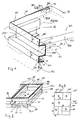
- FIG. 1 shows the oblique view of the corner area of a modular elements according to the invention
- Fig. 2 is an oblique view sketch of a whole, rectangular such modular element and part of a second such Element according to the invention
- Fig. 3 is the view of a variant Connection of two modular elements positioned "in alignment" with one another
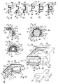
- FIGS. 4 to 6 the sketches of cuts through the enclosing frame strips of two, lying side by side interconnected modular elements
- Fig. 7 is a diagram for the assembly a multitude of modularly coordinated, modular elements according to the invention to a flat construct
- FIGS. 8 to 13 different profile or cross-sectional shapes of the enclosing frame or of its circumferential groove-like recess
- FIGS. 17 and 18 are views of two preferred forms of Miter connecting plates, the connecting plate of FIG. 18 simultaneously the Connection of a leg or the like.
- Fig. 19 enables a cross-like connecting body for the connection of four modular elements at their corners
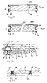
- FIG. 20 a modular floor stone with washed concrete filling
- Fig. 21 a climate wall element and 22 a heatable floor stone
- FIG. 23 a schematic sketch for the technology from its laying
- Fig. 24 is the schematic oblique view of one with a Miter connection plate and an additional corner stabilizer body equipped mitred corner of the frame of the new modular element
- FIG. 25 is a schematic plan view of a module frame corner, which with a Frame corner ligature body is stabilized
- Fig. 26 in a schematic sectional view preferred embodiment of a spacer for the construction of a screen wall structure from the new modular elements
- Fig. 27 is a schematic sectional view of such a formed blend structure
- FIGS. 28 and 29 different embodiments of the Holding head of the spacer mentioned.
- Fig. 1 it can be seen how on the inner region of the corner 250 of the Enclosure frame 100 of a modular element 10 two mutually perpendicular arranged frame strips 200 via a miter joint 25 - preferably by Weld - are joined together.
- the profiles of the frame strips 200 have one - Between two side contact flanks 23 arranged in a geometric plane EG same width b - rectangular cross-sectional shape encircling the frame corner 250 having groove or channel-like circulation recess 2, which are made up of the total Longitudinal recesses 20 with here flat bottom 21 and groove side walls on both sides 22 are formed.
- the inner edges 212 between the bottom 21 and side walls 22 of the Recess 20 and / or the outer edges 223 thereof must face the two flanks 23 not, as shown, be sharp-edged, rather they are conveniently rounded educated.
- the profile of the frame strips 200 shown here also has one of lower of the two edges 234 of the flanks 23 going out, towards the frame interior IR backward edge extension 24, which with the lower flank 23 - possibly also rounded - edge 234 forms.
- the edge extension 24 has the advantage that it is mechanical stabilization and rigidity of the enclosing frame 100 essential contributes. Under certain circumstances, he can represent the filling of the frame Surface element 90, e.g. a plate or the like, hold on the edge.
- the marginal extension 24 is specifically provided only on one side of the profile 200. Of course, one can such marginal process also at an obtuse or acute angle p than 90 ° from the Extend flanks 22 to the inside of the frame IR. With the edge zone 9020 its Main surface 902 on the underside of the plate-shaped surface element 90 Enclosure frame 100 or on its upper groove wall 22, and can - if desired - to the same, e.g. be bound by gluing.
- the surface element 90 With its flank surfaces 903, the surface element 90 lies here on the inside upper of the two side contact flanks 23 of the frame 100. It can be done upon completion of the frame 100 is introduced into this as a filling and possibly fixed there. 1 shows an edge-side recess 94 of the surface element 90, which access to a bar 200, preferably arranged centrally with respect to the length of the bar, Feedthrough or connection opening 280 in the upper flank 23 of the frame 100 enables which opening e.g. the implementation of a supply line or Connection line or its coupling or the like, for the transmission of energy, data flows or the like, from the element 10 shown to an adjacent element of a floor, wall or other structure formed from the modular elements according to the invention, allows.
- a supply line or Connection line or its coupling or the like for the transmission of energy, data flows or the like
- Fig. 2 shows here - in comparison to Fig. 1 constant Reference sign meanings - an oblique view of a modular element according to the invention 10 with a frame 100 enclosing the surface element 90 filling it here, formed from Frame strips 200 with recess 20, whose profile on the underside also towards the inside pointing edge extension 24. It also shows how the enclosing frame 100 with its total formed from the groove-like longitudinal recesses 20 Circulation recess 2 in a desired connection with the enclosing frame 100 'of a second modular element 10' positioned side by side and ultimately is also bound.
- FIG. 3 shows one while maintaining the other meanings of the reference symbols aligned arrangement of two modular elements 10, 10 'with some of them here cut frame 100, 100 'and with a frame filling 90 and further, as by Insert one of the cross-sectional shape of the groove-like longitudinal recesses 20, 20 ' correspondingly shaped longitudinal connection profile 303 or such a body 304 of the here as a U-profile extends over the joint 1000 of the two frames 100, 100 ', the modular elements 10, 10 'are interconnected.
- FIG. 5 shows how a plate 90 arranged on the underside in the space between Groove wall 22, lower flank 23 and edge extension 24 is held, while in the Modular elements 10, 10 'of FIG. 6 that fill the frames 100, 100' Surface elements 90 extend from the lower to the upper edge extension 24, and e.g. With Concrete are formed.
- the sketch does not require any special explanation from one of several different ones modular elements having modular dimensions 10, 10 ', 10 ", 10"' with their Module frame 100, 100 ', 100 ", 100'” ... composite wall construction or the like. 7, with the other meanings of reference numerals with the Meanings of the reference numerals in the previous figures are identical.
- the Aspect ratios of the rectangular modular elements are set to 1: 2 or 1: 1.
- module dimensions of any other numerical ratio such as e.g. according to the type of paper format according to DIN.
- each of the enclosing frames 100 of the modular elements 10 circumferential groove-like longitudinal recesses 20, namely, with a rectangular, semi-trapezoidal, trapezoidal, semi-oval-round, omega-shaped and angular-omega-shaped or diagonal-square cross section.
- the 8 to 13 also show different arrangements of the surface element 90, which fills the respective enclosing frame 100.
- 14 to 16 show module-element transverse and also longitudinal connecting bodies 301 or profiles 302 for merging modular elements 10, 10 ', 10 ", 10"', .... with panel fillings 90, specifically those for an L or angled one, for a T-shaped and a star-shaped combination of the modular elements 10, 10 ', 10 "...
- the connecting bodies 301 or profiles 302 are each with the Alignment of the enclosing frames 100, 100 ', 100 "... or the modular elements 10, 10 ', 10 “... connection projections 3010, 3020 which are oriented in relation to one another equipped, which with the cross-sectional shapes of the recesses 20, 20 ', 20 “, 20'” ... the mentioned framework can cooperatively cooperate.
- the surface element 90 itself can also act as a miter connecting plate.
- the the aforementioned binding of the miter connection plate 400 to the frame 100 can by any type of fastening means, by gluing or, as indicated in FIG. 17, by spot welding 425.
- the triangular miter joint plate 400 of the Fig. 18 bears downwards, a bolt 450 with an external thread 451 on which e.g. a leg 80 or the like. for a table-like module frame according to the invention, such as he e.g. in model railroad construction can be put together to form a large underlay can be screwed on.
- the cruciform connector body 305 shown in FIG. 19 is capable of four in one-level, corner-to-corner abutting modular elements to bind to each other, the circumferential groove recesses of their Enclosure frame 100 each have a semi-trapezoidal cross-sectional shape.
- the modular floor laying block 10 of FIG. 20 has one of the same as before enclosure frame 100 again described, the surface element 90th performing- concrete block formed. This has 901 exposed concrete structure on its top on. With the side or flank surfaces 903, the stone is due to the effect of inorganic binder extremely stable with the entire inside of the enclosing frame 100 self-adhesive.
- a stone like the one shown in Fig. 20 is suitable e.g. not just for conventional floors, but also e.g. for boards to be laid between and on both sides of Tram tracks, for indoor pools and the like.
- the construction of health-promoting, breathing and optimally regulating the room moisture content enables bioclimatic wall structures, but practically only on the building site assembly and connection of the delivered and through their frames 100 also particularly stable climate wall modules 10 needs to take place.
- the modular element 10 of FIG. 22 designed as a floor heating stone or plate is with an enclosure frame 100, as previously described in detail formed, which encloses a surface element 90 formed with three layers.
- the surface element 90 has an upper, e.g. formed with a stone slab Impact layer 93 occurs, down to which a layer 95 of a hardened Embedding compound into which either a flat resistance heating winding 970 or through which a heat transfer fluid can flow, e.g. flat meandering, Heating pipes 971 is or are embedded.
- the modular floor heating element closes on the underside 22 with a layer 96 of a heat insulating material, e.g. one Mineral fiber fleece, from.
- a recess 94 is arranged, through which, preferably ledge-centered, opening 260 of the enclosure frame 100 a power supply line 60 for the heating winding 970 from the adjacent heating block 10 'and is introduced.
- Fig. 23 shows only schematically, e.g. on a rough surface using e.g. hollow profile-like spacers 750 which lie side by side with each other connected modular base plate elements 10, 10 'according to the invention can be properly laid.
- one of the frame mitres 25 shows the other previous ones Reference sign meanings, as can be seen from FIG. 18, on the upper groove side wall 22 bonded miter connecting plate 400, which downward via spot welds with one of its two side faces 411 to the Bottoms 21 of the grooves 20 of the miter strips 200, e.g. also by Weld, bonded stabilizer square hollow profile body 410 is connected to what an extremely stable, fully enclosing frame 100 against any angular distortion securing construction is realized.
- the aforementioned, welded nut 452 increases the mechanical stability of the Stabilizer hollow body 410 itself and thus the miter 25 and the enclosing frame 100 still further. 24 that the height hs of the Stabilizer body 410 is identical to the width bb of the longitudinal recess bottom 21.
- FIG. 25 shows a top view of another advantageous solution for the miter connection 25 at the corners 250 of the module enclosing frame 100. It is about preferably by means of adhesive, on the inside of the groove bottoms 21 of the corner-connected Frame strips 200 are a two-legged corner ligature 430 made of a plastic material bound, which is reinforced in the area of its corner towards the inside and there a connection element, for example one equipped with an internal thread Recess 453 for a connection with the threaded bolt of a leg, one Cantilever arm, a hanging eye or the like. having.
- each of the two legs 432 of the ligature body 430 further an anchoring element, e.g. a threaded holes 4325, which for the (screw) anchoring of connecting elements, for example wing screws 3002, for the positionally stable attachment of e.g. 4 to 6 and 14 to 16 Connection bodies 301, 302 shown or of their connection extensions 3010 for the Combining several modular elements to form a wall structure or the like. intended are.
- anchoring element e.g. a threaded holes 4325, which for the (screw) anchoring of connecting elements, for example wing screws 3002, for the positionally stable attachment of e.g. 4 to 6 and 14 to 16 Connection bodies 301, 302 shown or of their connection extensions 3010 for the Combining several modular elements to form a wall structure or the like. intended are.
- the ligature body 430 preferably has one with the width of the groove base 21 identical thickness or height, similar to the above for the stabilizer hollow body 410 described.
- FIG. 26 shows one on one, e.g. already existing, wall 70 anchored spacer 440 with foot part 441 and head part 442, which here over his Extension 4421 is detachably connected to said foot part 441.
- the foot portion 441 and / or the extension 4421 of the holding head 442 Elongated hole 4410, which is penetrated by a connecting screw 4401.
- the holding and connecting head 442 itself is here as essentially with the Longitudinal recess 20 of the enclosing frame 100 fit-cooperating profile educated.
- the frames 100, 100 'of the modular elements 10, 10' are by means of Screw connection 3003 connected to each other and thereby simultaneously on the head 442 of the Spacers 440 held snugly.
- Connecting elements e.g. Screws 3004.
- a gap filling and cover strip 851 e.g. clamped or screwed, arranged.
- Fig. 27 shows the diagram of one with the spacers just described 440 and several modular elements 10, 10 ', 10 "... formed” diaphragm wall "structure 75 in Sectional view.
- the modular elements 10, 10 ', 10 "... of such a wall are preferred, for example as "Indoor climate modules", such as shown in Fig. 20, or as sound absorption elements or the like. educated.
- FIG. 28 and 29 show schematic sectional view sketches of two more Embodiments of the module retention and connection heads 442 of the spacers 440 or of the profiles forming them, the profile of FIG. 28 being designed such that it overall is resilient and after the modular elements 10 and 10 'are put on or pushed in or from their adjacent frames 100, 100 'through the elements mentioned Preload and spring clamp hold while the profile 442 of FIG. 29 on its two free ends is formed with resilient zones 4422.
Landscapes
- Engineering & Computer Science (AREA)
- Architecture (AREA)
- Civil Engineering (AREA)
- Structural Engineering (AREA)
- Physics & Mathematics (AREA)
- Electromagnetism (AREA)
- Joining Of Building Structures In Genera (AREA)
- Audible-Bandwidth Dynamoelectric Transducers Other Than Pickups (AREA)
- Battery Mounting, Suspending (AREA)
Claims (14)
- Elément modulaire de table, de parois, de plancher ou de plafond ayant au moins un cadre entourant un élément de surface ou de plaque ou d'insertion, qui peut être joint à au moins un autre cadre entourant un autre élément de surface similaire ou non et peut être relié à celui-ci pour former une structure composée essentiellement plane, le cadre d'entourage (100) individuel, qui peut être relié avec des autres cadres d'entourage (100', 100") des éléments modulaires (10', 10") égaux ou dimensionnés d'une manière accordée l'un à l'autre de façon modulaire et ayant un contour extérieur, de préférence rectangulaire ou carré, étant formé par des listeaux de cadre (200) reliés mutuellement de manière amovible ou non par soudage ou pareil au moyen des onglets (25) et ayant des profiles de section similaire entre eux, dont chacun comprend un creux longitudinal (20) de façon approximative d'une rainure ou rigole, ouvert vers l'extérieur, qui de son part est accompagné des deux côtés par des flancs de contiguïté latéraux (23) s'étendant transversalement à elle même et étant situés dans un plan géométrique commun (EG) de manière que le cadre d'entourage (100) tous ensemble comprend un creux entourant (2), qui l'entoure et est ouvert de tout côté vers l'extérieur, caractérisé en ceque le cadre d'entourage (100) de l'élément de surface (90) ou les listeaux (200) individuelles formant le cadre comportent seulement à un côté un prolongement de bord (24), qui s'étend du bord libre (234) d'un des flancs de contiguïté latéraux (23) accompagnant le creux longitudinal (20) vers l'intérieur (IR) et au centre du cadre (100) transversalement, de préférence sous un angle droit (ρ), en relation audit flanc (23),au moins un des flancs de contiguïté latéraux (23) du cadre d'entourage (100) ainsi formé et/ou la surface intérieure du fond de rainure ou de creux (21) étant disposé tellement, que sa surface intérieure porte bien essentiellement le long du contour au surfaces (903) d'un élément de surface (90) d'une forme plaine ou de plaque ou bien tridimensionnel, qui est entouré par celui-ci, et/ou - essentiellement aussi le long du contour - au moins un paroi de rainure ou de creux (22) et/ou le prolongement de bord (24) porte bien à la zone de bord (9010, 9020) du côté supérieur ou inférieur (901, 902) de l'élément de surface (90) entouré par lui, de préférence étant lié audit élément de surface (90) soit de manière amovible, soit de manière indétachable.
- Elément modulaire selon la revendication 1, caractérisé en ce qu'au moins un des listeaux de cadre (200) du cadre d'entourage (100) - qui est disposé de manière symétrique relativement à son extension longitudinale et, le cas échéant, aussi relativement à son extension en large - comporte au moins un creux (260), particulièrement pour le passage des conduits d'énergie, d'alimentation et/ou des données, d'information et/ou de commande (60).
- Elément modulaire selon la revendication 1 ou 2, caractérisé en ce que les listeaux de cadre (200) formant son cadre d'entourage (100) sont formés d'un matériau métallique et/ou plastique au moins peu gauchissant, qui de préférence peut être relié par soudage dans les zones des onglets (25), au moins dans des zones partielles de ceux-ci, préférablement d'un matériau métallique formé (à froid) ou laminé (à froid) à base d'aluminium, d'acier ou d'acier spécial.
- Elément modulaire selon une quelconque des revendications 1 à 3, caractérisé en ce que dans chaque zone des angles et/ou coins (250) du cadre d'entourage (100) individuel soit une plaque ou angle (400) d'assemblage d'onglet ou pareil, qui relie les listeaux de cadre (200) joignant l'onglet est disposé, préférablement lié à une des deux parois latéraux (22) des creux longitudinaux (20), et/ou soit un corps de stabilisation (410), préférablement formé d'une pièce de profile creux rectangulaire ou carré est disposé, dont deux de ses côtés (411) sont liés au côté intérieur aux fonds (21) des creux longitudinaux (20) des listeaux de cadre (200) joignant l'onglet.
- Elément modulaire selon une quelconque des revendications 1 à 4, caractérisé en ceque la plaque ou l'angle (400) d'assemblage d'onglet ou pareil individuel(le) et/ou le corps de stabilisation (410) ou pareil est relié avec les listeaux de cadre (200) reliés par les onglets d'angle (25), particulièrement avec une des parois latéraux (22) ou les fonds (21), par un assemblage par boulons ou rivé, de préférence au moyen d'un assemblage soudé, soudé par points (425), par brasage ou collage et/ouque les plaques ou l'angles (400) d'assemblage d'onglet ou pareil et/ou les corps de stabilisation (410) ou pareil sont équipés des éléments ou organes de fonction (450), par exemple des boulons filetés, des écrous filetés, des organes d'assemblage à enclenchement, des organes de connexion mâle-femelle ou pareil pour l'adjonction, l'attachage ou pareil des écarteurs, des bras, des contre-fiches (d'assemblage), des boulons (d'assemblage), des jambes de support (80), des éléments flexibles de suspension et/ou de connexion, comme p.e. des câbles, des chaínes, des fils métalliques, des oeillets, des anneaux, des pinces, des brides et/ou pareil.
- Elément modulaire selon une quelconque des revendications 1 à 5, caractérisé en cequ'il comprend un corps de ligature des coins de cadre (430) à deux branches, préférablement d'un matériau polymère rigide, lié au côté intérieur des fonds (21) des creux longitudinaux (20) des listeaux de cadre (200) joignant l'onglet au moyen de collage dans chaque zone d'un angle et/ou coin (250) du cadre d'entourage (100), dont l'hauteur ou épaisseur de matière est, de préférence, égal à la largeur desdites fonds (21) des creux longitudinaux (20) des listeaux de cadre (200) etque le corps de ligature des coins de cadre (430) est équipé des creux ou des bosses d'assemblage à enclenchement, des alésages filetés, des écrous filetés, des goupilles (450, 451) ou boulons filetées ou pareil pour l'assemblage des organes de fonction (450), comme particulièrement des boulons filetés, des écrous filetés, des organes d'assemblage à enclenchement, des organes de connexion mâle-femelle ou pareil pour l'adjonction, l'attachage ou pareil des écarteurs, des bras, des contre-fiches (d'assemblage), des boulons (d'assemblage), des jambes de support (80), des éléments flexibles de suspension et/ou de connexion, comme p.e. des câbles, des chaínes, des fils métalliques, des oeillets, des anneaux, des pinces, des brides et/ou pareil, etque de préférence le corps de ligature des coins de cadre (430) comprend dans au moins un de ses deux branches (432) un élément d'ancrage, par exemple un filet femelle ou un écrou fileté (4325), intégré dans lui-même pour l'ancrage d'un élément de fixation, par exemple d'une vis, d'une vis à oreilles (3002) ou pareil pour fixer un corps (401) ou profile (402) de connexion situé dans le creux longitudinal de cadre (20), le cas échéant coopérant d'une manière clabotée, pour assembler l'élément modulaire (10) avec au moins un autre élément (10').
- Elément modulaire selon une quelconque des revendications 1 à 6, caractérisé en ceque les creux longitudinaux (20) des listeaux de cadre (200) ont une forme en profile essentiellement carrée ou rectangulaire, au moins les deux arêtes intérieurs (212) et/ou la base ou le fond (21) du creux (20) est ou sont arrondi(s), et/ouque les creux longitudinaux (20) des listeaux de cadre (200) individuels ont une forme en profile essentiellement s'élargissant vers la base ou le fond (21) situé au côté intérieur du creux (20), par exemple approximativement en demi-queue d'aronde, essentiellement en forme d'icositétraèdre ou demi-icositétraèdre, ou bien rhomboïdale ou deltoïde, au moins les deux arêtes intérieurs et/ou la base ou le fond (21) du creux (20), le cas échéant, étant arrondi(s), et/ouque les creux longitudinaux (20) des listeaux de cadre (200) individuels ont une forme en profile essentiellement s'élargissant en forme concave vers la base ou le fond (21) situé au côté intérieur du creux (20), de préférence en forme du majuscule grec d'oméga (Ω).
- Elément modulaire selon une quelconque des revendications 1 à 7, caractérisé en cequ'il est formé avec un élément de surface (90) en forme de panneau ou de plaque, qui porte bien ou est lié à au moins une des zones individuelles (22, 24) du cadre d'entourage (100) ou de ses listeaux de cadre (200), qui le forment, mais préférablement au côté intérieur d'une de ses parois de rainure (22), ouqu'il est formé avec au moins deux éléments de surface (90, 90') en forme de panneau ou de plaque, qui portent bien sur au moins une partie de surface et, le cas échéant, sont lié l'un à l'autre ou bien sont espacé l'un de l'autre, et qui portent bien et/ou sont liés chacun à au moins une des zones individuelles (22, 24) du cadre d'entourage (100),la liaison pouvant être effectuée préférablement par des moyens de liaison mécaniques, particulièrement au moyen d'une connexion par vis ou rivet.
- Elément modulaire selon une quelconque des revendications 1 à 8, caractérisé en ceque l'élément de surface (90) en forme de feuille, de plaque ou de panneau, et est formé avec de bois, de bois stratifié, d'une matière de bois, d'un matériau de papier ou de carton, d'une matière plastique, d'un matériau nid d'abeilles, d'une nappe de fibres, d'un tissu, d'une grille (spatiale) ou pareil de matière plastique, de métal, de minéral, de céramique, de verre et/ou d'une matière textile, avec de pierre, de pierre artificiel, d'un matériau d'argile ou de terre durcis, d'une matière durcie et, le cas échéant, armée à la base d'un liant organique ou minéral, particulièrement de béton, de chaux, de plâtre ou pareil ou avec des combinaison d'au moins deux desdits matériaux, et/ouqu'un élément de surface (90) en forme de panneau, qui porte bien au moins à la supérieure des parois de rainure (22), de préférence de bois ou d'un matériau de bois, est entouré par le cadre d'entourage (100) pour des buts de présentation, particulièrement pour la fabrication d'installations de maquettes, le bord supérieur (234) dudit cadre (100) et/ou, le cas échéant, son prolongement (24) étant essentiellement aligné ou à fleur avec la surface extérieure (901) de l'élément de surface (90), et/ouqu'un élément de surface (90) en forme de panneau ayant, de préférence de bois ou d'un matériau de bois, une forme correspondante aux buts d'emmagasinage et de dépôt, pour des systèmes d'ordre ou pareil, particulièrement pour des produits de type de tiroir, de caisse ou d'auge, et qui porte bien au moins à la supérieure des parois de rainure (22) est entouré par le cadre d'entourage (100), le bord supérieur (234) dudit cadre (100) et/ou, le cas échéant, son prolongement (24) étant essentiellement aligné ou à fleur avec la surface extérieure (901) de l'élément de surface (90), et/ouqu'il est formé - particulièrement pour former une parois de climatisation, un plafond de climatisation ou de tel revêtement de sol - avec un matériau de terre durcis, particulièrement d'argile, qui porte bien, et de préférence est lié par adhésion inhérante, à des zones (21, 22, 23 ou 24), préférablement à tout le côté intérieur et donc à toutes zones (21, 22, 23, 24) du cadre d'entourage (100), au moins un côté (901) dudit matériau étant garni, enduit, couvert ou pareil par une matière de fibres végétales (9011), particulièrement de jute (tissu ou filet), un matériau de roseaux et/ou un autre matériau végétal de tige et/ou de fibres, p.e. des fibres de coco, et/ouqu'il est formé avec un matériau de béton, qui porte bien au moins partiellement, mais de préférence substantiellement en totalité, au côté intérieur du cadre d'entourage (100) et est préférablement lié, pris et cuit par adhésion inhérente, de préférence ayant une structure visible, particulièrement de béton lavé, et/ouque l'élément de surface (90) - pour former un pierre de chauffage de sol, de parois ou de plafond, une telle plaque ou pareil - est formé avec au moins une couche d'élément de surface (9) en forme de panneau ou de plaque, au moins non-calorifuge - disposée au côté en vue ou d'usage et/ou de pas - et avec au moins une couche d'élément de surface (95) de création ou d'échange de chaleur substantiellement plane aussi, qui comprend une résistance de chauffage (970) disposée en nappe, préférablement dans une masse de lit (97), ou avec un système de tubes (971) disposée en nappe, préférablement dans une telle masse (97), pour être passé par un fluide caloporteur, la couche extérieur (9) de l'élément de surface et la couche d'élément de création ou d'échange de chaleur (95) étant entourées par le cadre d'entourage (100), au moins une des zones (22, 24) en étant porté bien et, le cas échéant, lié à celle-ci.
- Elément modulaire selon une quelconque des revendications 1 à 9, caractérisé en ceque sa couche d'élément de surface (9) en forme de panneau ou de plaque, disposée au côté en vue ou d'usage et/ou de pas, est formée avec un matériau de pierre, par exemple de schiste, de marbre, de travertin ou pareil, et(ouqu'il comprend, additionnellement à la couche d'élément de surface (9) disposée au côté en vue ou d'usage et/ou de pas et à la couche d'élément de surface (95) de création ou d'échange de chaleur, une couche de recouvrement de panneau (96), au côté inférieur ou arrière, d'un ou avec un matériau soit inhibiteur au flux thermique et/ou refrénant ou isolant au bruits de chocs, préférablement d'un matériau de laine minérale, de toison, d'un produit alvéolaire ou pareil, qui est entourée aussi par le cadre d'entourage (100).
- Elément modulaire selon une quelconque des revendications 1 à 10, caractérisé en cequ'au moins un corps de connexion transversale (301) ou un profile de connexion transversale (302) est prévu pour l'assemblage en contiguïté latérale, la connexion ou la jonction avec au moins un autre élément (10') de même nature ou dimensionné correspondement d'une manière modulaire, qui a une forme en profile correspondante ou adaptée au profile de deux creux longitudinaux (20, 20') contigus l'un à l'autre à l'occasion du positionnement des cadres d'entourage (100, 100') ou des listeaux de cadre (200, 200') en contiguïté latérale, qui forment ceux-ci, ledit corps (301) ou ledit profile (302) coopérant d'une manière clabotée, d'engrènement, de serrage (élastique) et/ou par une connexion de talon avec chacune desdits creux longitudinaux (20, 20') des listeaux de cadre (200, 200'), dont ses flancs de contiguïté latéraux (23, 23') sont positionné en contiguïté et qui sont à relier, ou bien qu'un corps de connexion de quatre modules (305) ou un tel profile est prévu substantiellement en forme de croix, dont la forme, particulièrement la forme en profile, correspond au corps (301) ou profile (302) de connexion décrit ci-dessus, qui relie quatre éléments modulaires, et/ouque, pour l'assemblage en contiguïté aligné, la connexion ou la jonction avec au moins un autre élément (10') modulaire, un corps de connexion longitudinale (303) ou un profile de connexion transversale (304) est prévu, qui superpose les creux longitudinaux (20, 20') des cadres d'entourage (100, 100') alignés l'un à l'autre dans la zone de joint (1000) de ceux-ci et comprend une forme en profile ou au moins un contour extérieur correspondant ou adapté au profile desdits creux longitudinaux (20, 20'), qui coopère d'une manière clabotée, d'engrènement, de serrage (élastique) et/ou par une connexion de talon avec lesdits creux longitudinaux (20, 20') des cadres d'entourage (100, 100') à relier, ou bien qu'un corps de connexion de quatre modules (305) ou un tel profile est prévu substantiellement en forme de croix, dont la forme, particulièrement la forme en profile, correspond au corps (301) ou profile (302) de connexion décrit ci-dessus, qui relie quatre éléments modulaires, et/ouqu'au moins un corps (301) ou profile (302) de connexion de coins ou bords est prévu pour la connexion ou jonction avec au moins un autre élément (10') modulaire s'étendant sous un angle (α), préférablement droit, audit premier élément modulaire (10), ledit corps ou profile pouvant être inséré dans les deux creux longitudinaux (20, 20') des cadres d'entourage (100, 100') disposés l'un à l'autre sous cet angle (α) et ayant des prolongations de connexion (3010, 3020), qui ont une forme en profile correspondante ou adaptée au profile des creux longitudinaux (20, 20') et sont orientées l'une à l'autre sous ledit angle (α), lesdites prolongations de connexion (3010, 3020) coopérant d'une manière clabotée, d'engrènement, de serrage (élastique) et/ou par une connexion de talon avec chacun des creux longitudinaux (20, 20') des cadres d'entourage (100, 100') des éléments modulaires (10, 10') à disposer sous l'angle (α) et à relier entre eux, et/ouque pour l'assemblage et la connexion ou jonction avec plus qu'un seul d'autres éléments modulaire (10', 10", 10,'" ...) voisin audit premier élément modulaire (10) et disposés sous des angles (α, β, γ ...) au ceci, au moins un corps (301) ou profile (302) de connexion est prévu, préférablement en forme de T, de croix ou d'étoile, dont les prolongations de connexion (3010, 3020) peuvent être insérés dans les creux longitudinaux (20, 20', 20", 20'"...) de tous les cadres d'entourage (100, 100', 100", 100'" ...) à relier, lesdites prolongations de connexion (3010, 3020) coopérant d'une manière clabotée, d'engrènement, de serrage (élastique) et/ou par une connexion de talon avec chacun des creux longitudinaux (20, 20', 20", 20'" ...) des cadres d'entourage des éléments modulaires (10, 10', 10") disposés sous des angles (α, β, γ ...) et à relier entre eux.
- Elément modulaire selon une quelconque des revendications 1 à 11, caractérisé en ce que son élément de surface (90) comprend au moins un creux (94), qui, au côté du bord, est ouvert vers le cadre d'entourage (100) ou à une de ses zones (21, 22, 23) et, préférablement, au côté supérieur et/ou inférieur pour l'insertion d'un élément de connexion (3001) pour la connexion avec le cadre (100) d'un autre élément modulaire et/ou pour l'insertion ou l'amenage d'au moins un des conduits d'énergie, d'alimentation et/ou des données, d'information et/ou de commande (60).
- Elément modulaire selon une quelconque des revendications 1 à 12, caractérisé en ceque pour former une structure de parois écran (75) comprenant une pluralité d'éléments modulaires (10, 10' ...), par exemple ayant des revêtements bioclimatiques (voir revendication 9) et à disposer en distance d'une structure-support portante, particulièrement d'une muraille, parois (70) ou pareil, par exemple de construction conventionnelle,des écarteurs (440) sont prévus, qui peuvent être fixés à la dite structure-support (70) à être distant de celle-ci, et qui ont une partie de pied (441) et une tête support-module et de connexion (442) essentiellement similaire ou correspondante aux corps (301) ou profiles (302) de connexion décrits dans la revendication 11, qui sont adaptés à coopérer d'une manière en substance clabotée et à être introduits dans le creux longitudinal (20) du cadre (100), et qui préférablement sont formés comme ornière continue oblongue,ladite tête support-module et de connexion (442) étant, de préférence, formée avec un profile correspondant au profile d'au moins un des creux longitudinaux (20) d'un des cadres d'entourage (100) ou aux profiles des creux longitudinaux (20) des cadres d'entourage (100, 100') de deux éléments modulaires voisins, et/ouque la tête support-module et de connexion (442) de l'écarteur (440) est formé séparément de la partie de pied (441) et comprend un prolongement (4421) pour un assemblage détachable avec ladite partie de pied (441), un trou longitudinal (4410) étant prévu dans au moins une desdites parties pour une disposition de la tête support-module et de connexion (442), qui égalise des inexactitudes de montage ou pareil et pour le fixer au moyen d'un élément de connexion, par exemple une vis (4401), traversant ledit trou longitudinal.
- Elément modulaire selon une quelconque des revendications 1 à 13, caractérisé en ce que, pour couvrir des espaces, des fentes ou pareil existants par suite de l'épaisseur du matériau de la partie de pied (441) de l'écarteur (440) au côté détourné de la structure-support ou parois (70) conventionnelle, préférablement tourné vers l'intérieur du local, des couvre-joints (751) d'une matière polymère flexible ou élastique sont prévus entre les éléments modulaires (10, 10') formant la parois écran (75) et peuvent être introduits dans ces fentes et y étant, de préférence, maintenu par serrage.
Priority Applications (1)
| Application Number | Priority Date | Filing Date | Title |
|---|---|---|---|
| AT99890087T ATE247206T1 (de) | 1998-03-12 | 1999-03-10 | Modulares element und rahmen hierfür |
Applications Claiming Priority (4)
| Application Number | Priority Date | Filing Date | Title |
|---|---|---|---|
| AT44798 | 1998-03-12 | ||
| AT44798 | 1998-03-12 | ||
| AT97698 | 1998-06-05 | ||
| AT97698A AT407902B (de) | 1998-06-05 | 1998-06-05 | Modulares element |
Publications (2)
| Publication Number | Publication Date |
|---|---|
| EP0942108A1 EP0942108A1 (fr) | 1999-09-15 |
| EP0942108B1 true EP0942108B1 (fr) | 2003-08-13 |
Family
ID=25592767
Family Applications (1)
| Application Number | Title | Priority Date | Filing Date |
|---|---|---|---|
| EP99890087A Expired - Lifetime EP0942108B1 (fr) | 1998-03-12 | 1999-03-10 | Elément modulaire et encadrement |
Country Status (2)
| Country | Link |
|---|---|
| EP (1) | EP0942108B1 (fr) |
| DE (2) | DE59906552D1 (fr) |
Families Citing this family (6)
| Publication number | Priority date | Publication date | Assignee | Title |
|---|---|---|---|---|
| WO2005048782A2 (fr) * | 2003-11-19 | 2005-06-02 | Gunnar Manufacturing Inc. | Meubles permettant d'attenuer les effets d'un sinistre |
| DE202004011176U1 (de) * | 2004-07-15 | 2005-07-28 | Kuka Schweissanlagen Gmbh | Modulare Anlagenboden für Fertigungsanlagen |
| DE102005006169A1 (de) * | 2005-02-10 | 2006-08-17 | Eckard Wolf | Plattenelement vorzugsweise zum Einbau in eine Boden- oder Wandverkleidung insbesondere einen Fußbodenbelag |
| DE202006000706U1 (de) * | 2005-12-01 | 2006-08-03 | Sackmann, Lothar | Abdeckung für Formfedernuten |
| ES2365583B9 (es) * | 2009-09-21 | 2013-04-10 | Enquire S.L. | Cámara acústica desmontable. |
| IT1401983B1 (it) * | 2010-09-28 | 2013-08-28 | Alfredo Salvatori S R L | Dispositivo di supporto per una lastra di materiale edile per rivestimento. |
Family Cites Families (4)
| Publication number | Priority date | Publication date | Assignee | Title |
|---|---|---|---|---|
| FR1084219A (fr) * | 1953-05-22 | 1955-01-18 | élément de construction | |
| GB1132774A (en) * | 1966-02-24 | 1968-11-06 | Deutsche Bauakademie | Improved building panels |
| GB1285603A (en) * | 1969-09-15 | 1972-08-16 | Hans Brattrud | Panel element |
| DE3274477D1 (en) * | 1982-06-11 | 1987-01-15 | Egide Jozef Debremaeker | Building |
-
1999
- 1999-03-10 EP EP99890087A patent/EP0942108B1/fr not_active Expired - Lifetime
- 1999-03-10 DE DE59906552T patent/DE59906552D1/de not_active Expired - Lifetime
- 1999-03-12 DE DE29904630U patent/DE29904630U1/de not_active Expired - Lifetime
Also Published As
| Publication number | Publication date |
|---|---|
| EP0942108A1 (fr) | 1999-09-15 |
| DE29904630U1 (de) | 1999-06-02 |
| DE59906552D1 (de) | 2003-09-18 |
Similar Documents
| Publication | Publication Date | Title |
|---|---|---|
| EP1317587A1 (fr) | Batiment | |
| DE202009018931U1 (de) | Mobiles modulares Wandsystem | |
| EP0942108B1 (fr) | Elément modulaire et encadrement | |
| WO2006092262A1 (fr) | Cellule tridimensionnelle autoporteuse comportant des parois exterieures rapportees non-autoporteuses | |
| DE3326054A1 (de) | Unterdecke | |
| DE2452463A1 (de) | Traggerippe fuer eine unter eine gebaeudefeste decke aufzuhaengende unterdecke | |
| DE60033392T2 (de) | Gebäudekonstruktion | |
| DE202016008552U1 (de) | Ziegelverkleidungssystem | |
| AT407902B (de) | Modulares element | |
| DE19801370A1 (de) | Tafelelement | |
| DE202018005071U1 (de) | Modulares multifunktionales Bauteilesystem zum Erstellen von Wänden, Flächen, Decken, Gebäuden, Fundamenten und Fassaden | |
| DE3722849A1 (de) | Schnellbau-trennwand fuer die einrichtung von kabinen und abtrennungen im sanitaer- und nassbereich | |
| EP0120292A2 (fr) | Elément de construction | |
| DE102020004760A1 (de) | Baustein zur errichtung von mauern und stützen eines gebäudes | |
| DE3247039A1 (de) | Verbundsystem zur bildung von bauelementen | |
| DE3644726C2 (de) | Fassadendämmelement mit Hinterlüftung | |
| DE2513067A1 (de) | Raumbildendes bauelement, insbesondere fuer behelfsbauten, sowie bauwerke aus solchen bauelementen | |
| CH625297A5 (en) | Set of structural elements for a building | |
| DE102007049332A1 (de) | Bausatz zur Errichtung eines Gebäudes | |
| DE102004060288B4 (de) | Gebäudemodul | |
| EP0826844B1 (fr) | Colonne en bois par collage pour méthode de construction d'une ossature en bois | |
| DE10050312A1 (de) | Raumzelle | |
| DE4302871A1 (de) | Haus aus Fertigbauelementen | |
| EP1197715A2 (fr) | Cellule de bâtiment | |
| DE10315441A1 (de) | Modulbaustein und Verfahren zur Verlegung desselben |
Legal Events
| Date | Code | Title | Description |
|---|---|---|---|
| PUAI | Public reference made under article 153(3) epc to a published international application that has entered the european phase |
Free format text: ORIGINAL CODE: 0009012 |
|
| AK | Designated contracting states |
Kind code of ref document: A1 Designated state(s): AT CH DE DK FI FR LI SE |
|
| AX | Request for extension of the european patent |
Free format text: AL;LT;LV;MK;RO;SI |
|
| 17P | Request for examination filed |
Effective date: 20000221 |
|
| AKX | Designation fees paid |
Free format text: AT CH DE DK FI FR LI SE |
|
| GRAH | Despatch of communication of intention to grant a patent |
Free format text: ORIGINAL CODE: EPIDOS IGRA |
|
| GRAH | Despatch of communication of intention to grant a patent |
Free format text: ORIGINAL CODE: EPIDOS IGRA |
|
| GRAA | (expected) grant |
Free format text: ORIGINAL CODE: 0009210 |
|
| AK | Designated contracting states |
Designated state(s): AT CH DE DK FI FR LI SE |
|
| PG25 | Lapsed in a contracting state [announced via postgrant information from national office to epo] |
Ref country code: FR Free format text: LAPSE BECAUSE OF NON-PAYMENT OF DUE FEES Effective date: 20030813 Ref country code: FI Free format text: LAPSE BECAUSE OF FAILURE TO SUBMIT A TRANSLATION OF THE DESCRIPTION OR TO PAY THE FEE WITHIN THE PRESCRIBED TIME-LIMIT Effective date: 20030813 |
|
| REG | Reference to a national code |
Ref country code: CH Ref legal event code: EP |
|
| REF | Corresponds to: |
Ref document number: 59906552 Country of ref document: DE Date of ref document: 20030918 Kind code of ref document: P |
|
| REG | Reference to a national code |
Ref country code: CH Ref legal event code: NV Representative=s name: BUECHEL, VON REVY & PARTNER |
|
| PG25 | Lapsed in a contracting state [announced via postgrant information from national office to epo] |
Ref country code: SE Free format text: LAPSE BECAUSE OF FAILURE TO SUBMIT A TRANSLATION OF THE DESCRIPTION OR TO PAY THE FEE WITHIN THE PRESCRIBED TIME-LIMIT Effective date: 20031113 Ref country code: DK Free format text: LAPSE BECAUSE OF FAILURE TO SUBMIT A TRANSLATION OF THE DESCRIPTION OR TO PAY THE FEE WITHIN THE PRESCRIBED TIME-LIMIT Effective date: 20031113 |
|
| PLBE | No opposition filed within time limit |
Free format text: ORIGINAL CODE: 0009261 |
|
| STAA | Information on the status of an ep patent application or granted ep patent |
Free format text: STATUS: NO OPPOSITION FILED WITHIN TIME LIMIT |
|
| 26N | No opposition filed |
Effective date: 20040514 |
|
| EN | Fr: translation not filed | ||
| PGFP | Annual fee paid to national office [announced via postgrant information from national office to epo] |
Ref country code: CH Payment date: 20120326 Year of fee payment: 14 |
|
| PGFP | Annual fee paid to national office [announced via postgrant information from national office to epo] |
Ref country code: DE Payment date: 20120323 Year of fee payment: 14 |
|
| PGFP | Annual fee paid to national office [announced via postgrant information from national office to epo] |
Ref country code: AT Payment date: 20120312 Year of fee payment: 14 |
|
| REG | Reference to a national code |
Ref country code: CH Ref legal event code: PL |
|
| REG | Reference to a national code |
Ref country code: AT Ref legal event code: MM01 Ref document number: 247206 Country of ref document: AT Kind code of ref document: T Effective date: 20130310 |
|
| REG | Reference to a national code |
Ref country code: DE Ref legal event code: R119 Ref document number: 59906552 Country of ref document: DE Effective date: 20131001 |
|
| PG25 | Lapsed in a contracting state [announced via postgrant information from national office to epo] |
Ref country code: DE Free format text: LAPSE BECAUSE OF NON-PAYMENT OF DUE FEES Effective date: 20131001 Ref country code: LI Free format text: LAPSE BECAUSE OF NON-PAYMENT OF DUE FEES Effective date: 20130331 Ref country code: CH Free format text: LAPSE BECAUSE OF NON-PAYMENT OF DUE FEES Effective date: 20130331 Ref country code: AT Free format text: LAPSE BECAUSE OF NON-PAYMENT OF DUE FEES Effective date: 20130310 |