EP0942138A2 - Abstützelement einer Glasscheibe - Google Patents
Abstützelement einer Glasscheibe Download PDFInfo
- Publication number
- EP0942138A2 EP0942138A2 EP99101432A EP99101432A EP0942138A2 EP 0942138 A2 EP0942138 A2 EP 0942138A2 EP 99101432 A EP99101432 A EP 99101432A EP 99101432 A EP99101432 A EP 99101432A EP 0942138 A2 EP0942138 A2 EP 0942138A2
- Authority
- EP
- European Patent Office
- Prior art keywords
- support element
- clamping part
- element according
- profile frame
- hollow profile
- Prior art date
- Legal status (The legal status is an assumption and is not a legal conclusion. Google has not performed a legal analysis and makes no representation as to the accuracy of the status listed.)
- Granted
Links
- 239000011521 glass Substances 0.000 claims abstract description 9
- 210000002105 tongue Anatomy 0.000 claims description 59
- 238000006073 displacement reaction Methods 0.000 abstract description 2
- 238000003780 insertion Methods 0.000 description 4
- 230000037431 insertion Effects 0.000 description 4
- XLYOFNOQVPJJNP-UHFFFAOYSA-N water Substances O XLYOFNOQVPJJNP-UHFFFAOYSA-N 0.000 description 4
- 239000000463 material Substances 0.000 description 3
- 238000004519 manufacturing process Methods 0.000 description 2
- 230000003313 weakening effect Effects 0.000 description 2
- 239000011324 bead Substances 0.000 description 1
- 238000005553 drilling Methods 0.000 description 1
- 230000000694 effects Effects 0.000 description 1
- 238000007373 indentation Methods 0.000 description 1
- 238000002347 injection Methods 0.000 description 1
- 239000007924 injection Substances 0.000 description 1
- 238000001746 injection moulding Methods 0.000 description 1
- 238000009434 installation Methods 0.000 description 1
- 239000002184 metal Substances 0.000 description 1
- 230000000284 resting effect Effects 0.000 description 1
Images


Classifications
-
- E—FIXED CONSTRUCTIONS
- E06—DOORS, WINDOWS, SHUTTERS, OR ROLLER BLINDS IN GENERAL; LADDERS
- E06B—FIXED OR MOVABLE CLOSURES FOR OPENINGS IN BUILDINGS, VEHICLES, FENCES OR LIKE ENCLOSURES IN GENERAL, e.g. DOORS, WINDOWS, BLINDS, GATES
- E06B3/00—Window sashes, door leaves, or like elements for closing wall or like openings; Layout of fixed or moving closures, e.g. windows in wall or like openings; Features of rigidly-mounted outer frames relating to the mounting of wing frames
- E06B3/54—Fixing of glass panes or like plates
- E06B3/5409—Means for locally spacing the pane from the surrounding frame
Definitions
- the invention relates to a support element Glass pane according to the preamble of claim 1.
- Such a support element is disclosed in EP 0 745 749 A1. It sits between a hollow profile frame and one Glass pane / glazing and supports both against each other.
- a clamping part-holding projection pairing available for Fixing to the profile frame is on a longitudinal edge of the support element a clamping part-holding projection pairing available.
- the retaining projection of this pairing grips perpendicular to the frame plane form-fitting in the undercut on a groove wall a seal receiving groove formed in a rollover is.
- the clamping part is on the underside of the support element supported on a longitudinal edge of the profile frame, so that the support element is fixed overall in a form-fitting manner is.
- the support element must be used to produce the positive connection be locked in the hollow profile frame. There is a deformation of the support element required.
- the support element has to simplify the latching a weak point in the area of the angle of the retaining projection. This weak point is kinked when inserted, so that the holding projection is spread vertically from the support element is. This is the mounting position of the support element. Such a vulnerability is provided so that the Latching necessary deformation of the support element causes can be. The support element then gives when locked in the area of the vulnerability.
- the weakness is in shown embodiment formed as a film hinge.
- Such a targeted vulnerability requires a certain amount Instability of the support element.
- the whole arrangement will thereby weakened and is not kept completely rigid overall.
- the weak point can always yield under stress and move the support element.
- Such a vulnerability also has the disadvantage that they tear easily can. This can be done in the mounting position as well done during assembly itself.
- the invention is based on the object an easy-to-lock support element with weak spots Cross section on rigid profile frame sections across its longitudinal extension practically rigid and secure against displacement to keep.
- the support element at least one in the mounting position perpendicular to the plane of the pane arranged spring tongue.
- the spring tongue carries the retaining projection and / or the clamping part.
- the horizontally arranged The spring tongue can then be latched transversely to the support element swing or give way. This allows the spring tongue when the retaining projection-clamping part pair is locked are slightly elastically deformed so that the locking position with only little effort can be achieved without the support element is damaged.
- a spring tongue preferably has no structural, in particular cross-sectional weakenings of the support element. Only a spring action is required, which is a component in the frame level must have to the latching like to enable mentioned above.
- the support element can be practically without sacrificing the Strength of the form fit on only one of its longitudinal edges be attached.
- This is already with simple profile frame design the firm seat realized.
- the longitudinal outside edge of the support element as above described in a form-fitting manner.
- Profiling of the profile frame is particularly advantageous be exploited.
- the frame rollover Seal receiving grooves provided that a seat for offer the holding projection.
- the grooves mentioned are adjacent arranged, and offer enough cross-section for the arrangement of Holding projection-clamping part pairing.
- the outside profile sections are usually also special stable. In particular, they are mostly in one piece to attempt burglary to be able to withstand.
- the glazing of a Window is from the inside of the room. After insertion the glass pane becomes the glass retaining strip on the frame profile attached. Therefore, it is usually very advantageous that the entire definition of the support element on one of its longitudinal edges takes place, namely the longitudinal edge arranged on the outside. This technical necessity is in the present Advantageously exploited invention.
- a particularly preferred embodiment provides that the spring tongues through transverse slots open on the longitudinal edge side of the support element are formed.
- the spring tongues with the in between slots can be used in injection molding of the support element already provided in the injection mold be.
- the slots can also be formed after the support element be introduced. Then you can just saw them be. This offers a particularly variable manufacturing option for a support element.
- the length of the spring tongues should be such that it enable easy locking. Here is the travel to be interpreted accordingly long.
- the spring tongue to extend into the support element, however only to the extent that the stability of the support element is practical is not affected.
- the length is preferably too choose that both the retaining projection and the clamping part are arranged in the resilient area of the spring tongue.
- the transverse slots are on the longitudinal edge side of the support element open and extend from a longitudinal edge of the support element starting in the supporting part of the support element in, perpendicular to the frame plane. This creates a spring force achieved, which are influenced by the slot length can. On the other hand, the length of the spring tongues should be dimensioned that the support element is still firm and rigid within in its intended position.
- the invention offers for the first time the possibility that a supporting element to be locked holding projection and / or Clamping part are loaded with stiffening elements. Then the seat of the support element is particularly secure. Holding tab and / or clamping part are then stiffened. Is preferred to this, that only either a retaining projection or a Clamping part is acted upon by a stiffening element. Then the other partner of the holding pair can spring relatively freely. If the stiffening elements are completely inside the spring tongues can sit, both retaining projection and clamping part additionally have stiffening elements. Then they spring Stiffening elements of the spring tongues with. It is advantageous here that the retaining projection and clamping part are particularly stable and can be rigid, so that no deformation of the retaining projection and clamping part and also no tearing of these parts fear.
- the holding projection in the undercut is preferably one Groove of the hollow profile frame latches or is supported against the undercut or against an undercut-free projection lock-free. It is further preferred that the Clamping part designed as a support-side web of the support element is.
- the clamping part can also be used as a bead or a massive projection of the support element or one under one Spring tongue inserted block to be formed, the holding projection holds in its resting position.
- the support element can also be designed in this way be that the web in its rest position on the profile floor lies on. Then it is preferred that the clamping part and retaining projection are arranged longitudinally offset from one another.
- the invention has the advantage that the support element is also easy to assemble / lock when it is over its cross section practically free of weak points is. This advantage is achieved by giving in of the holder pair largely caused by the spring tongues is. Then no weak point in the material is needed to to enable simple latching.
- a particularly preferred embodiment provides that more than one retaining projection and / or more than one clamping part are / is present, and alternately on the longitudinal edge of the support element are distributed. These can be as described above engage and / or cooperate elastically, so that a particularly tight fit is achieved. If the holding projections and / or clamping parts are arranged in a longitudinally offset manner are, the support element is also against rotation in the Support surface level secured.
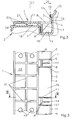
- the glass pane is in a hollow profile frame 2 installed of which only one profile piece is shown is.
- the hollow profile has hollow chambers, not shown here. It is a plastic hollow profile frame.
- the invention can also be used on metal profile frames.
- the support element can also be designed as a glazing rebate insert be on a block serving to support the glass pane is arranged.
- the support element 1 has a total of three retaining projections 3. All holding projections 3 are on a longitudinal edge 4 of the support element 1 arranged. They protrude essentially at right angles in the vertical direction upwards over a support surface 21 of the support element 1.
- the free ends 5 of the Retaining projections 3 are perpendicular to the disc plane 27 (see Fig. 3) held positively. For this they are in the undercut 15 a groove 16 of the hollow profile frame 2 locked. Of the Undercut 15 of the groove 16 is through the groove wall of a seal receiving groove 25 formed. This is particularly advantageous since apart from the seal receiving groove 25 there are no further separate ones Grooves must be provided in the hollow profile frame 2.
- the Support element 1 can simply be cut into the existing undercut 15 used and locked there. This simplifies the Production of the hollow profile frame 2. It can also be a Standard hollow profile frame 2 are used, provided the support element 1 has the appropriate dimensions.
- the support element 1 also has a vertical of the support surface 21 angled clamping part 6 (see Fig. 3).
- the clamping part 6 is on a bottom longitudinal edge 7 of the hollow profile frame 2 locked.
- the longitudinal edge 7 is through the one lying on the outside of the room in the exemplary embodiment shown Groove wall of a water drain groove 19 is formed.
- the support element 1 has horizontal in its mounting position arranged spring tongues 8.9 on which the holding projections 3 and the clamping parts 6 are arranged.
- the spring tongues 8, 9 is the support element 1 on its Longitudinal edge 4 beginning transverse slots 11, 12 provided.
- the Cross slots 11, 12 run practically perpendicular to the pane plane 27. You can also angle within a horizontal plane if they are a component perpendicular to the Have disc direction. Then it is always guaranteed that Holding projections 3 and clamping parts 6 arranged on the spring tongues and are freely deflected in the vertical direction can, provided the transverse slots are open on the longitudinal edge side.
- the transverse slots 11, 12 only extend around the Amount of a fraction of the width of the support element 1 in this in, preferably not beyond its middle. Then is the structural stability of the support element 1 through the transverse slots 11, 12 are practically not disturbed.
- the holding projections 3 and clamping parts 6 are on the same Longitudinal edge 4 of the support element 1 longitudinally offset from one another and arranged without overlap.
- the spring tongues 8 each carry a clamping part 6.
- the spring tongues 9 each carry one Retaining projection 3.
- the spring tongues 8 do not have a retaining projection 3 and the spring tongues 9 do not have a clamping part 6.
- the support element 1 is between the undercut 16 and the longitudinal edge 7 of the water drainage groove 19 locked.
- the support element 1 is also in the direction 26 set perpendicular to the disc plane 27.
- the spring tongues 8.9 are in opposite vertical directions curious; excited. This creates a holding force in the Undercut 16 or on the longitudinal edge 7. This holding force presses holding projections 3 and clamping parts 6 in their respective Seat and thus reinforces the seat through self-locking of the support element 1.
- the self-locking in direction 26 perpendicular to the slice level is preferably a multiple larger than that required for the insertion of the support element 1 Locking forces.
- the support element 1 is practical over its cross section trained without weak spots. In particular, the material the support element 1 no weakening, the stability would affect. Because of the spring tongues 8.9 easy locking without any weak points possible.
- the holder pairings can practically any wall thickness have and do not have to with taper or with be made smaller thickness.
- FIG. 2 shows the embodiment of the support element 1 seen from Fig. 1 from below.
- the support element 1 is with Support webs 20 supported on the profile floor 18 of the hollow profile frame 2.
- the clamping parts 6 can be seen in this illustration.
- the holding projections 3 are due to the material of the spring tongues 9 covered and shown in dashed lines.
- the clamping parts 6 have stiffening elements 14.
- FIG 3 the section is as in Figure 2 by the dash-dotted line Line indicated and seen in the direction of arrows III shown.
- the stiffening elements 14 from the See page They are designed as filled corner angles. They run between the clamping part 6, which as the support side Web of the support element 1 is formed, and the spring tongue 8. They stiffen the clamping part 6 opposite the spring tongue 8, so that these two projections cannot or practically cannot deform against each other.
- the web that forms the clamping part 6 lies in it Rest position on the profile floor 18. This is it Clamping part 6 additionally a support for the spring tongue 8.
- Das Clamping part 6 conducts z. B. pressure loads resulting from the glazing on the spring tongue 8 on the profile floor 18 and thus supports the spring tongue 8 on the underside.
- the section of Figure 3 is performed through the transverse slot 12.
- the spring tongue 8 is in the foreground.
- the retaining projection 3 can be seen which is in the undercut 15 the groove 16 is locked.
- the free end 5 of the retaining projection 3 a contour adapted to the contour of the groove 16.
- the free end 5 runs in vertical direction towards the outside of the window and is pointed locked in the undercut 15 of the groove 16 with this tip.
- the groove 16 is through a wall of the seal receiving groove 25 formed. This seal receiving groove 25 is practical always present on the outside of the window so that their Wall for the horizontal, form-fitting fixing of the support element 1 can be used.
- the support web 20 of the support element arranged inside the room 1 engages in a receiving groove 24 of the hollow profile frame 2 a. This causes an improved, horizontal Fixing the support element 1; with the horizontal direction here is the direction 26 perpendicular to the disk plane 27 meant.
- FIG. 4 shows the view of a further exemplary embodiment of the support element 1 seen from below.
- the holding projections 3 and the clamping parts are exemplary embodiments 6 each on the same spring tongues 9 and on the tongue 28 arranged.
- the tongue 28 can - also in the embodiment 2 - have a certain spring effect despite their length, which simply snap and all other advantages of the Invention conditional.
- the bracket pair is namely jammed against each other on the same spring tongues. Nevertheless, the spring tongues make a resilient insertion of the support element 1 enables.
- the spring tongues can yield when forces occur. For example first the retaining projection 3 in the undercut 15 are used. Then the clamping part 6 under Deformation of the spring tongues 8.9 and the tongue 28 on the Longitudinal edge 7 are locked.
- FIG 4 the section along the section line is in FIG 4 shown in the direction of arrows V, VI.
- Clamping part 6 and holding projection 3 are arranged on the spring tongue 9.
- the Clamping part 6 is stiffened with a stiffening element 14.
- the holding projections 3 have in this embodiment an overall tapering in the vertical direction Contour with its tip in the undercut 15 intervenes and is positively fixed there.
- the clamping part 6 is supported on the groove bottom 18.
- Fig. 6 shows another embodiment. Here it is Clamping part 6 shortened. It does not rest on the profile floor 18 onwards. It is spaced from this. This has the Advantage that the clamping part 6 with less effort the longitudinal edge 7 is to be locked.
- This configuration is particularly advantageous. The required Deformation of the spring tongue 9 is then comparatively low. The support element 1 can thus be used more easily become. Nevertheless, with this configuration, it is storage-safe Definition of the support element 1 given. A Shifting to the inside of the room could only against the deformation resistance of the clamping part 6. This would also be the case extremely high deformation forces required, so that the support element 1 is very tight.
Landscapes
- Engineering & Computer Science (AREA)
- Civil Engineering (AREA)
- Structural Engineering (AREA)
- Securing Of Glass Panes Or The Like (AREA)
- Laminated Bodies (AREA)
- Joining Of Glass To Other Materials (AREA)
Abstract
Description
- Fig.1
- eine perpektivische Ansicht eines horizontalen Profilstücks eines Hohlprofilrahmens mit eingesetztem Abstützelement,
- Fig.2
- eine Draufsicht auf das Abstützelement der Fig.1 von unten gesehen,
- Fig.3
- einen Schnitt durch dieses Abstützelement entlang der in Fig.2 gezeigten Schnittlinie in Richtung der Pfeile III gesehen,
- Fig.4
- eine Draufsicht auf ein anderes Abstützelement, ebenfalls von unten gesehen,
- Fig.5
- einen Schnitt durch das Abstützelement der Fig.4 entlang der Schnittlinie in Fig.4 und in Richtung der Pfeile V und VI gesehen, und
- Fig.6
- einen Querschnitt wie in Fig.5 mit vom Boden beabstandetem Klemmteil.
- 1
- Abstützelement
- 2
- Hohlprofilrahmen
- 3
- Haltevorsprung
- 4
- Längskante des Abstützelements
- 5
- freies Ende des Haltevorsprungs
- 6
- Klemmteil
- 7
- Bodenlängskante
- 8
- Federzunge
- 9
- Federzunge
- 11
- Querschlitz
- 12
- Querschlitz
- 14
- Versteifungselement
- 15
- Hinterschnitt
- 16
- Nut
- 18
- Profilboden
- 19
- Wasserablaufnut
- 20
- Auflagesteg
- 21
- Abstützfläche
- 22
- Unterseite des Abstützelements
- 23
- Bohrung
- 24
- Aufnahmenut
- 25
- Dichtungsaufnahmenut
- 26
- Richtung senkrecht zur Scheibenebene
- 27
- Scheibenebene
- 28
- Zunge
Claims (12)
- Abstützelement (1) einer Glasscheibe, die in einen Hohlprofilrahmen (2) eingebaut ist, mit einem an einer Längskante (4) angeordneten Haltevorsprung (3), der mit einem freien Ende am Hohlprofilrahmen (2) senkrecht zur Scheibenebene (27) abgestützt ist, und mit einem Klemmteil (6), das an einer Bodenlängskante (7) des Hohlprofilrahmens (2) verrastet ist, dadurch gekennzeichnet, daß das Abstützelement (1) zumindest eine in Montagestellung senkrecht zur Scheibenebene (27) angeordnete Federzunge (8,9,28) aufweist, an der der Haltevorsprung (3) und/oder das Klemmteil (6) angeordnet sind/ist.
- Abstützelement nach Anspruch 1, dadurch gekenntzeichnet, daß die Federzungen (8,9,28) durch längskantenseitig offene Querschlitze (11,12) des Abstützelements (1) gebildet sind.
- Abstützelement nach Anspruch 1 oder 2, dadurch gekennzeichnet, daß Haltevorsprung (3) und Klemmteil (6) an derselben Längskante (4) des Abstützelements (1) zueinander längsversetzt und überlappungsfrei angeordnet sind.
- Abstützelement nach Anspruch 3, dadurch gekennzeichnet, daß Haltevorsprung (3) und Klemmteil (6) an unterschiedlichen Federzungen (8,9,28) angeordnet sind.
- Abstützelement nach einem der Ansprüche 1 bis 4, dadurch gekennzeichnet, daß unterschiedliche Federzungen (8,9) in Montagestellung in entgegengesetzter Vertikalrichtung gespannt sind.
- Abstützelement nach einem der Ansprüche 1 bis 5, dadurch gekennzeichnet, daß Haltevorsprung (3) und/oder Klemmteil (6) mit Versteifungselemente (14) beaufschlagt sind.
- Abstützelement nach einem der Ansprüche 1 bis 6, dadurch gekennzeichnet, daß der Haltevorsprung (3) in dem Hinterschnitt (15) einer Nut (16) des Hohlprofilrahmens (2) verrastet ist oder sich gegen den Hinterschnitt (15) oder gegen einen hinterschnittfreien Vorsprung verrastungsfrei abstützt.
- Abstützelement nach einem der Ansprüche 1 bis 6, dadurch gekennzeichnet, daß das Klemmteil (6) als auflageseitiger Steg des Abstützelementes (1) ausgebildet ist.
- Abstützelement nach Anspruch 8, dadurch gekennzeichnet, daß der Steg in seiner Raststellung vom Profilboden (18) beabstandet angeordnet ist.
- Abstützelement nach Anspruch 8, dadurch gekennzeichnet, daß der Steg in seiner Raststellung auf dem Profilboden (18) aufliegt.
- Abstützelement nach einem der Ansprüche 1 bis 10, dadurch gekennzeichnet, daß das Abstützelement (1) über seinen Querschnitt praktisch schwachstellenfrei ausgebildet ist.
- Abstützelement nach einem der Ansprüche 1 bis 11, dadurch gekennzeichnet, daß mehr als ein Haltevorsprung (3) und/oder mehr als ein Klemmteil (6) vorhanden sind/ist, und einander abwechselnd an der Längskante (4) des Abstützelements verteilt sind.
Applications Claiming Priority (2)
| Application Number | Priority Date | Filing Date | Title |
|---|---|---|---|
| DE29804555U DE29804555U1 (de) | 1998-03-13 | 1998-03-13 | Abstützelement einer Glasscheibe |
| DE29804555U | 1998-03-13 |
Publications (3)
| Publication Number | Publication Date |
|---|---|
| EP0942138A2 true EP0942138A2 (de) | 1999-09-15 |
| EP0942138A3 EP0942138A3 (de) | 2000-03-15 |
| EP0942138B1 EP0942138B1 (de) | 2005-08-10 |
Family
ID=8054133
Family Applications (1)
| Application Number | Title | Priority Date | Filing Date |
|---|---|---|---|
| EP99101432A Expired - Lifetime EP0942138B1 (de) | 1998-03-13 | 1999-01-27 | Abstützelement einer Glasscheibe |
Country Status (3)
| Country | Link |
|---|---|
| EP (1) | EP0942138B1 (de) |
| AT (1) | ATE301762T1 (de) |
| DE (2) | DE29804555U1 (de) |
Family Cites Families (4)
| Publication number | Priority date | Publication date | Assignee | Title |
|---|---|---|---|---|
| DE8236198U1 (de) * | 1982-12-23 | 1983-09-01 | Niemann, Hans-Dieter, 5014 Kerpen | Klotzbruecke oder gitterklotz zum festsetzen von glasscheiben od. dgl. in tuer- oder fensterrahmen |
| ES2046699T3 (es) * | 1989-08-11 | 1994-02-01 | Glazpart Ltd | Un conjunto de panel. |
| DE29509133U1 (de) * | 1995-06-02 | 1996-10-02 | Niemann, Hans-Dieter, 50169 Kerpen | Abstützelemente einer Glasscheibe |
| DE29608742U1 (de) * | 1996-05-14 | 1996-08-01 | Sommer Metallbau-Stahlbau GmbH & Co KG, 95182 Döhlau | Verbundprofil |
-
1998
- 1998-03-13 DE DE29804555U patent/DE29804555U1/de not_active Expired - Lifetime
-
1999
- 1999-01-27 DE DE59912374T patent/DE59912374D1/de not_active Expired - Lifetime
- 1999-01-27 EP EP99101432A patent/EP0942138B1/de not_active Expired - Lifetime
- 1999-01-27 AT AT99101432T patent/ATE301762T1/de not_active IP Right Cessation
Also Published As
| Publication number | Publication date |
|---|---|
| DE59912374D1 (de) | 2005-09-15 |
| DE29804555U1 (de) | 1999-07-15 |
| EP0942138A3 (de) | 2000-03-15 |
| EP0942138B1 (de) | 2005-08-10 |
| ATE301762T1 (de) | 2005-08-15 |
Similar Documents
| Publication | Publication Date | Title |
|---|---|---|
| EP0436869A2 (de) | Verbindung des Stosses zwischen Riegel und Pfosten an einem Traggerippe für eine oder an einer Fassadenwand | |
| EP0745749A1 (de) | Abstützelement einer Glasscheibe od. dgl. | |
| DE2920445A1 (de) | Verschlussanordnung mit verglasung | |
| EP1932997A2 (de) | Oberer Abschluss einer Schwelle Abschluss-System sowie Schwelle | |
| DE2812128C3 (de) | Wärmeisolierender Profilkörper | |
| AT411378B (de) | Rahmenverbreiterung für ein fenster oder eine tür | |
| DE202006004287U1 (de) | Keilvorrichtung | |
| EP0942138B1 (de) | Abstützelement einer Glasscheibe | |
| EP1186723B1 (de) | Haltevorrichtung für eine Riegel-Pfosten-Fassade | |
| DE102006012390A1 (de) | Keilvorrichtung | |
| EP2132391B1 (de) | Treibstangenanordnung mit mindestens einer treibstange und mindestens einem treibstangenführungselement | |
| DE2750351A1 (de) | Profilkonstruktion | |
| DE29820399U1 (de) | Abstützelement einer Glasscheibe | |
| DE19803984C2 (de) | Fassadenkonstruktion für polygonzugartigen Grundriß | |
| DE60202279T2 (de) | Rahmen zum festhalten einer plattenförmigen tafel | |
| DE102020106365A1 (de) | Bodenschwelle | |
| DE2553801A1 (de) | Rahmenkonstruktion fuer tueren, fenster u.dgl. | |
| DE19815219C2 (de) | Befestigungskonstruktion für mit Kanälen versehenen Fassadenplatten | |
| DE29808988U1 (de) | Glasfalzeinlage | |
| DE9318070U1 (de) | Steckverbinder für Sprossenprofile | |
| DE2814511A1 (de) | Waermeisolierender profilkoerper | |
| DE8803303U1 (de) | Schließblech für Türverschlüsse | |
| DE8323028U1 (de) | Verbinder fuer sprossenfenster und dergleichen | |
| DE20217734U1 (de) | Riegelelement und Beschlagseinheit | |
| DE202006018739U1 (de) | Treibstangengetriebe |
Legal Events
| Date | Code | Title | Description |
|---|---|---|---|
| PUAI | Public reference made under article 153(3) epc to a published international application that has entered the european phase |
Free format text: ORIGINAL CODE: 0009012 |
|
| AK | Designated contracting states |
Kind code of ref document: A2 Designated state(s): AT CH DE FR GB LI NL |
|
| AX | Request for extension of the european patent |
Free format text: AL;LT;LV;MK;RO;SI |
|
| PUAL | Search report despatched |
Free format text: ORIGINAL CODE: 0009013 |
|
| AK | Designated contracting states |
Kind code of ref document: A3 Designated state(s): AT BE CH CY DE DK ES FI FR GB GR IE IT LI LU MC NL PT SE |
|
| AX | Request for extension of the european patent |
Free format text: AL;LT;LV;MK;RO;SI |
|
| 17P | Request for examination filed |
Effective date: 20000411 |
|
| AKX | Designation fees paid |
Free format text: AT CH DE FR GB LI NL |
|
| 17Q | First examination report despatched |
Effective date: 20030214 |
|
| GRAP | Despatch of communication of intention to grant a patent |
Free format text: ORIGINAL CODE: EPIDOSNIGR1 |
|
| GRAS | Grant fee paid |
Free format text: ORIGINAL CODE: EPIDOSNIGR3 |
|
| GRAA | (expected) grant |
Free format text: ORIGINAL CODE: 0009210 |
|
| RAP1 | Party data changed (applicant data changed or rights of an application transferred) |
Owner name: NIEMANN, HANS DIETER |
|
| RIN1 | Information on inventor provided before grant (corrected) |
Inventor name: NIEMANN, HANS DIETER |
|
| AK | Designated contracting states |
Kind code of ref document: B1 Designated state(s): AT CH DE FR GB LI NL |
|
| PG25 | Lapsed in a contracting state [announced via postgrant information from national office to epo] |
Ref country code: NL Free format text: LAPSE BECAUSE OF FAILURE TO SUBMIT A TRANSLATION OF THE DESCRIPTION OR TO PAY THE FEE WITHIN THE PRESCRIBED TIME-LIMIT Effective date: 20050810 Ref country code: GB Free format text: LAPSE BECAUSE OF FAILURE TO SUBMIT A TRANSLATION OF THE DESCRIPTION OR TO PAY THE FEE WITHIN THE PRESCRIBED TIME-LIMIT Effective date: 20050810 |
|
| REG | Reference to a national code |
Ref country code: GB Ref legal event code: FG4D Free format text: NOT ENGLISH |
|
| REG | Reference to a national code |
Ref country code: CH Ref legal event code: EP |
|
| REF | Corresponds to: |
Ref document number: 59912374 Country of ref document: DE Date of ref document: 20050915 Kind code of ref document: P |
|
| PG25 | Lapsed in a contracting state [announced via postgrant information from national office to epo] |
Ref country code: AT Free format text: LAPSE BECAUSE OF NON-PAYMENT OF DUE FEES Effective date: 20060127 |
|
| PG25 | Lapsed in a contracting state [announced via postgrant information from national office to epo] |
Ref country code: LI Free format text: LAPSE BECAUSE OF NON-PAYMENT OF DUE FEES Effective date: 20060131 Ref country code: CH Free format text: LAPSE BECAUSE OF NON-PAYMENT OF DUE FEES Effective date: 20060131 |
|
| NLV1 | Nl: lapsed or annulled due to failure to fulfill the requirements of art. 29p and 29m of the patents act | ||
| GBV | Gb: ep patent (uk) treated as always having been void in accordance with gb section 77(7)/1977 [no translation filed] |
Effective date: 20050810 |
|
| PLBE | No opposition filed within time limit |
Free format text: ORIGINAL CODE: 0009261 |
|
| STAA | Information on the status of an ep patent application or granted ep patent |
Free format text: STATUS: NO OPPOSITION FILED WITHIN TIME LIMIT |
|
| 26N | No opposition filed |
Effective date: 20060511 |
|
| PG25 | Lapsed in a contracting state [announced via postgrant information from national office to epo] |
Ref country code: FR Free format text: LAPSE BECAUSE OF FAILURE TO SUBMIT A TRANSLATION OF THE DESCRIPTION OR TO PAY THE FEE WITHIN THE PRESCRIBED TIME-LIMIT Effective date: 20060811 |
|
| REG | Reference to a national code |
Ref country code: CH Ref legal event code: PL |
|
| EN | Fr: translation not filed | ||
| PG25 | Lapsed in a contracting state [announced via postgrant information from national office to epo] |
Ref country code: FR Free format text: LAPSE BECAUSE OF FAILURE TO SUBMIT A TRANSLATION OF THE DESCRIPTION OR TO PAY THE FEE WITHIN THE PRESCRIBED TIME-LIMIT Effective date: 20050810 |
|
| PGFP | Annual fee paid to national office [announced via postgrant information from national office to epo] |
Ref country code: DE Payment date: 20170127 Year of fee payment: 19 |
|
| REG | Reference to a national code |
Ref country code: DE Ref legal event code: R119 Ref document number: 59912374 Country of ref document: DE |
|
| PG25 | Lapsed in a contracting state [announced via postgrant information from national office to epo] |
Ref country code: DE Free format text: LAPSE BECAUSE OF NON-PAYMENT OF DUE FEES Effective date: 20180801 |