EP0942168A2 - Verfahren zur Verstellung der Rotorblätter einer Windkraftanlage - Google Patents
Verfahren zur Verstellung der Rotorblätter einer Windkraftanlage Download PDFInfo
- Publication number
- EP0942168A2 EP0942168A2 EP99104854A EP99104854A EP0942168A2 EP 0942168 A2 EP0942168 A2 EP 0942168A2 EP 99104854 A EP99104854 A EP 99104854A EP 99104854 A EP99104854 A EP 99104854A EP 0942168 A2 EP0942168 A2 EP 0942168A2
- Authority
- EP
- European Patent Office
- Prior art keywords
- rotor
- rotor blades
- blades
- wind
- angular
- Prior art date
- Legal status (The legal status is an assumption and is not a legal conclusion. Google has not performed a legal analysis and makes no representation as to the accuracy of the status listed.)
- Withdrawn
Links
- 238000000034 method Methods 0.000 claims description 20
- 230000000903 blocking effect Effects 0.000 claims description 3
- 238000013459 approach Methods 0.000 claims 1
- 230000001419 dependent effect Effects 0.000 abstract 1
- 230000000694 effects Effects 0.000 description 2
- 238000004364 calculation method Methods 0.000 description 1
- 238000001514 detection method Methods 0.000 description 1
- 238000011161 development Methods 0.000 description 1
- 230000018109 developmental process Effects 0.000 description 1
- 230000008030 elimination Effects 0.000 description 1
- 238000003379 elimination reaction Methods 0.000 description 1
- 230000000763 evoking effect Effects 0.000 description 1
- 238000004088 simulation Methods 0.000 description 1
Images

Classifications
-
- F—MECHANICAL ENGINEERING; LIGHTING; HEATING; WEAPONS; BLASTING
- F03—MACHINES OR ENGINES FOR LIQUIDS; WIND, SPRING, OR WEIGHT MOTORS; PRODUCING MECHANICAL POWER OR A REACTIVE PROPULSIVE THRUST, NOT OTHERWISE PROVIDED FOR
- F03D—WIND MOTORS
- F03D7/00—Controlling wind motors
- F03D7/02—Controlling wind motors the wind motors having rotation axis substantially parallel to the air flow entering the rotor
- F03D7/022—Adjusting aerodynamic properties of the blades
- F03D7/0224—Adjusting blade pitch
-
- Y—GENERAL TAGGING OF NEW TECHNOLOGICAL DEVELOPMENTS; GENERAL TAGGING OF CROSS-SECTIONAL TECHNOLOGIES SPANNING OVER SEVERAL SECTIONS OF THE IPC; TECHNICAL SUBJECTS COVERED BY FORMER USPC CROSS-REFERENCE ART COLLECTIONS [XRACs] AND DIGESTS
- Y02—TECHNOLOGIES OR APPLICATIONS FOR MITIGATION OR ADAPTATION AGAINST CLIMATE CHANGE
- Y02E—REDUCTION OF GREENHOUSE GAS [GHG] EMISSIONS, RELATED TO ENERGY GENERATION, TRANSMISSION OR DISTRIBUTION
- Y02E10/00—Energy generation through renewable energy sources
- Y02E10/70—Wind energy
- Y02E10/72—Wind turbines with rotation axis in wind direction
Definitions
- the invention relates to a method according to the preamble of claim 1 and a device that can be used advantageously to carry it out.
- Modern wind turbines with horizontal axis rotors have adjustable rotor blades, whereby the target surface is adapted to the wind speed and in one relatively large wind speed range an almost constant performance of the Plant can be observed.
- Such systems can still be compared operated at high wind speeds. Beyond an upper limit wind speed, for which the system is designed, however, must Limitation of mechanical loads and performance.
- the rotor blades are turned into a "flag position" or Low-load parking position, more precisely called “positive flag position” with counter the wind-oriented profile leading edge is provided.
- the critical Blade angle range in normal operation by appropriate control software or special safety circuits are blocked, because one the rotor in this Area gusts could generate such a high torque that hardly any controllable speed increase occurs.
- the second strategy uses a (sometimes called "negative flag" designated) parking position selected in which the profile trailing edges of the rotor blades are directed against the wind. This will reduce performance and Braking of the rotor is reached and the adjustment range to be realized is relative small.
- the set state is however unstable, the variant is with a high one Torsional stress on the individual rotor blade - and thus also a high one Load on the adjustment mechanism - connected, and there is a risk of dynamic Excessive loads.
- the invention is therefore based on the object, the generic method with the aim of simplifying the plant and the management and the To further improve operational security.
- the invention includes the idea of transferring the rotor blades into the To let the parking position run in a way that permanently blocks the car said critical blade angle range, i.e. driving through it basically not required.
- one of the rotor blades in the direction of rotation set in the first step is rotated further into the (positive) flag position, while the rotor through the still at an angle of approx. -20 ° to -90 ° compared to the normal operating position set remaining rotor blades is braked, and that in a third step and - depending on the total number of rotor blades - further steps the remaining rotor blades be rotated further into the flag position.
- the rotor blades are essentially at the same start time, but with different effective angular speeds in the direction of rotation set in the first step up to Flag position rotated further so that the rotor by at least one still in one
- the rotor blade located in the braking position is braked while at least one Another rotor blade is already approaching the flag position or has already reached it Has.
- the effective angular velocities of the rotor blades should be around distinguish at least a factor of 2.
- the starting point of the second step or further steps can in principle depending on the rotor position, i.e. the angular position of the rotor blades around the Rotor axis.
- the rotor position i.e. the angular position of the rotor blades around the Rotor axis.
- those with the lowest load for a specific system under defined conditions Determine and save rotor blade positions and via sensors for detection
- the leaf position can be the second step in reaching the saved Optimal position can be initiated.
- the adjustment of the rotor blades may also in the first step different effective angular velocity.
- the rotor blades can be adjusted continuously or discretely or in pulses, e.g. in predetermined angular steps.
- the procedure according to the invention enables surprisingly advantageous Way the structure of the adjustment device for the rotor blades with means for permanent blocking of a predetermined critical adjustment angle range (especially the range from about + 3 ° to + 70 °), so that this in normal operation not be run even in the event of a control error can.
- This locking can be done purely mechanically by means of fixed slings or by an electromechanical blocking and in this latter framework too software - but separate from the regular operating program and therefore with significantly increased security.
- the adjustment device preferably further comprises (known as such) Switching means, the at least one predetermined angular position of each rotor blade are assigned around its longitudinal axis and during routine referencing the rotor blades are used or to influence the in the event of a power failure or in any other accident initiated adjustment process, in particular to a positive opening emergency stop.
- Switching means the at least one predetermined angular position of each rotor blade are assigned around its longitudinal axis and during routine referencing the rotor blades are used or to influence the in the event of a power failure or in any other accident initiated adjustment process, in particular to a positive opening emergency stop.
- Switching means the at least one predetermined angular position of each rotor blade are assigned around its longitudinal axis and during routine referencing the rotor blades are used or to influence the in the event of a power failure or in any other accident initiated adjustment process, in particular to a positive opening emergency stop.
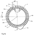
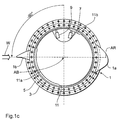
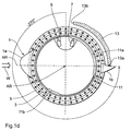
- FIG. 1a to 1d show the cross-sectional projection of a leading edge region 1a and a trailing edge area 1b of a rotor blade 1 onto the associated one Arrangement of a rotating ring 3 connected to the rotor blade and a outer bearing ring 5.
- An emergency switch 7 is also shown schematically in the figures and a so-called referencing switch 9, which with a curved path 11 on the Rotating ring 3 cooperate, and a mechanical lock 13 with two stop surfaces 13a and 13b.
- the cam track 11 comprises two control cams or Cams 11a and 11b.
- the representation of the mechanical lock 13 in one and the same figure level with the rotor blade cross section is considered to be purely schematic understand, i.e. in reality, of course, the lock does not grip the leaf profile itself but in the adjustment mechanism (not shown here).
- the projection of the rotor axis of rotation on the figure plane is with AR, the axis of rotation the blade angle adjustment with AB and the assumed wind direction with the arrow W denotes.
- a normal operating position of the rotor blade 1 (perpendicular to Wind direction) is assigned the angle of rotation value 0, and a rotation of the Rotor blade counterclockwise (or a hereby occupied Angular position), with a view of the rotor hub or figure level, is indicated by a marked negative sign, a clockwise rotation or one corresponding angular position with a positive sign.
- a first step of moving the rotor blade 1 into the parking position as shown in Fig. 1b - the sheet by 20 ° counterclockwise into one Brake position turned, i.e. transferred to the angular position -20 °.
- the emergency switch 7 and the referencing switch 9 act independently of the above described method, controlled by a normal operating control computer, in an emergency mode called a safety loop, as follows:
- the embodiment of the invention is not limited to the above specified preferred embodiment. Rather, a variety of Variants possible, which of the solution shown also in a different kind Use execution.
Landscapes
- Engineering & Computer Science (AREA)
- Physics & Mathematics (AREA)
- Fluid Mechanics (AREA)
- Life Sciences & Earth Sciences (AREA)
- Sustainable Development (AREA)
- Sustainable Energy (AREA)
- Chemical & Material Sciences (AREA)
- Combustion & Propulsion (AREA)
- Mechanical Engineering (AREA)
- General Engineering & Computer Science (AREA)
- Wind Motors (AREA)
Abstract
Description
Claims (10)
- Verfahren zur Verstellung der Rotorblätter (1) einer Windkraftanlage vom Horizontalrotor-Typ um ihre Längsachsen (AB) zur Überführung in eine lastarme Fahnenstellung (Fig. 1d), wobei die Profilhinterkanten (1b) der Rotorblätter in einem ersten Schritt, insbesondere um 20 bis 90°, zum Wind (W) hin in eine Bremsstellung (Fig. 1b) gedreht werden und mindestens eines der Rotorblätter in einem zweiten Schritt unabhängig von den übrigen verstellt wird, dadurch gekennzeichnet, daßin dem zweiten Schritt eines der Rotorblätter in die beim ersten Schritt eingestellte Drehrichtung bis in die positive Fahnenstellung weitergedreht wird, während der Rotor durch die übrigen Rotorblätter gebremst ist, undin einem dritten Schritt und gegebenenfalls weiteren Schritten die übrigen Rotorblätter in die positive Fahnenstellung weitergedreht werden.
- Verfahren zur Verstellung der Rotorblätter (1) einer Windkraftanlage vom Horizontalrotor-Typ um ihre Längsachsen (AB) zur Überführung in eine lastarme Fahnenstellung (Fig. 1d), wobei die Profilhinterkanten (1b) der Rotorblätter in einem ersten Schritt, insbesondere um 20 bis 90°, zum Wind hin in eine Bremsstellung (Fig. 1b) gedreht werden und mindestens eines der Rotorblätter in einem zweiten Schritt unabhängig von den übrigen verstellt wird, dadurch gekennzeichnet, daßin dem zweiten Schritt die Rotorblätter im wesentlichen zum gleichen Startzeitpunkt, jedoch mit unterschiedlicher effektiver Winkelgeschwindigkeit in die beim ersten Schritt eingestellte Drehrichtung bis in die positive Fahnenstellung weitergedreht werden, so daß der Rotor durch mindestens ein noch in einer Bremsstellung befindliches Rotorblatt gebremst ist, während mindestens ein weiteres Rotorblatt sich der Fahnenstellung nähert.
- Verfahren nach Anspruch 2, dadurch gekennzeichnet, daß die effektiven Winkelgeschwindigkeiten der Rotorblätter sich um mindestens den Faktor 2 unterscheiden.
- Verfahren nach einem der vorhergehenden Ansprüche, dadurch gekennzeichnet, daß die Verstellung der Rotorblätter in diskreten Schritten erfolgt.
- Verfahren nach einem der vorhergehenden Ansprüche, dadurch gekennzeichnet, daß der Startzeitpunkt des zweiten Schrittes und folgender Schritte in Abhängigkeit von der Rotorposition bestimmt wird.
- Vorrichtung zur Durchführung des Verfahrens nach einem der vorangehenden Ansprüche, gekennzeichnet durch Mittel (13) zur permanenten Sperrung eines vorbestimmten Verstellwinkelbereiches der Rotorblätter um ihre Längsachse.
- Vorrichtung nach Anspruch 6, dadurch gekennzeichnet, daß die Mittel zur permanenten Sperrung als feste mechanische Anschlagmittel (13a, 13b) ausgebildet sind.
- Vorrichtung nach Anspruch 6 oder 7, gekennzeichnet durch mindestens einer vorbestimmten Winkelstellung jedes Rotorblattes zugeordnete Schaltmittel (7, 9, 11) zur Beeinflussung, insbesondere Beendigung, eines Verstellvorganges und/oder zur Ausgabe eines Winkelpositionssignals bei Erreichen dieser Winkelstellung.
- Vorrichtung nach Anspruch 8, dadurch gekennzeichnet, daßdie Schaltmittel eine Nockeneinrichtung (11) und einen durch diese betätigten Schalter (7, 9) aufweisen.
- Vorrichtung nach Anspruch 9, dadurch gekennzeichnet, daß zur Ausführung aller erforderlichen Beeinflussungen und Winkelpositions-Signalausgaben genau zwei Schalter (7, 9) und eine Nockeneinrichtung (11) mit zwei Schaltkurven (11a, 11b) vorgesehen sind.
Applications Claiming Priority (2)
| Application Number | Priority Date | Filing Date | Title |
|---|---|---|---|
| DE19811952 | 1998-03-13 | ||
| DE19811952A DE19811952A1 (de) | 1998-03-15 | 1998-03-15 | Verfahren zur Verstellung der Rotorblätter einer Windkraftanlage |
Publications (2)
| Publication Number | Publication Date |
|---|---|
| EP0942168A2 true EP0942168A2 (de) | 1999-09-15 |
| EP0942168A3 EP0942168A3 (de) | 2001-10-17 |
Family
ID=7861448
Family Applications (1)
| Application Number | Title | Priority Date | Filing Date |
|---|---|---|---|
| EP99104854A Withdrawn EP0942168A3 (de) | 1998-03-13 | 1999-03-11 | Verfahren zur Verstellung der Rotorblätter einer Windkraftanlage |
Country Status (2)
| Country | Link |
|---|---|
| EP (1) | EP0942168A3 (de) |
| DE (1) | DE19811952A1 (de) |
Cited By (10)
| Publication number | Priority date | Publication date | Assignee | Title |
|---|---|---|---|---|
| WO2002099275A1 (de) * | 2001-06-07 | 2002-12-12 | Aloys Wobben | Schaltvorrichtung mit einer betätigungswelle |
| WO2003054388A1 (en) * | 2001-12-20 | 2003-07-03 | General Electric Company | Wind turbine in parked position |
| WO2003081032A1 (en) * | 2002-03-26 | 2003-10-02 | General Electric Company | Wind turbine blade feathering override |
| WO2006007838A1 (en) * | 2004-07-23 | 2006-01-26 | Vestas Wind Systems A/S | Method of controlling the pitch velocity of a wind turbine blade and control system therefore |
| WO2006096895A1 (de) * | 2005-03-18 | 2006-09-21 | Windtec Consulting Gmbh | Verfahren und vorrichtung zum abbremsen des rotors einer windkraftanlage |
| WO2009109309A3 (de) * | 2008-03-06 | 2010-05-06 | Repower Systems Ag | Blattwinkelverstellratengrenzwertanpassung |
| CN102146882A (zh) * | 2004-07-23 | 2011-08-10 | 维斯塔斯风力系统有限公司 | 控制风轮机叶片的倾斜速度的方法及其控制系统 |
| EP1701034A3 (de) * | 2005-03-09 | 2012-08-15 | Winwind Oy | Verfahren zum Anhalten eines Windenergieanlage Rotors |
| EP2535568A1 (de) * | 2006-01-11 | 2012-12-19 | REpower Systems AG | Verfahren zum Betreiben einer Windenergieanlage und Windenergieanlage |
| US10598159B2 (en) | 2016-05-06 | 2020-03-24 | General Electric Company | Wind turbine bearings |
Families Citing this family (6)
| Publication number | Priority date | Publication date | Assignee | Title |
|---|---|---|---|---|
| DE19948997B4 (de) | 1999-10-11 | 2005-04-14 | Aerodyn Engineering Gmbh | Einzelblattverstellung für Windenergieanlagen |
| DE10009472C2 (de) * | 2000-02-28 | 2002-06-13 | Norbert Hennchen | Vorrichtung zum Verstellen der Anstellwinkel der auf einer Nabe einer Rotorwelle verdrehbar angeordneten Rotorblätter einer Windkraftanlage |
| DE10106208C2 (de) | 2001-02-10 | 2002-12-19 | Aloys Wobben | Windenergieanlage |
| DE102004017323A1 (de) * | 2004-04-06 | 2005-11-03 | Repower Systems Ag | Windenergieanlage |
| DE102009017027A1 (de) * | 2009-04-14 | 2010-12-23 | Siemens Aktiengesellschaft | Windenergieanlage und Energieübertragungseinrichtung für eine Windenergieanlage |
| EP4056844B1 (de) * | 2021-03-12 | 2025-10-22 | General Electric Renovables España S.L. | Verfahren zur bestimmung einer pitchreferenz für ein pitchsteuerungssystem |
Citations (1)
| Publication number | Priority date | Publication date | Assignee | Title |
|---|---|---|---|---|
| DE19626402C1 (de) | 1996-07-01 | 1997-07-24 | Aerodyn Energiesysteme Gmbh | Verfahren zum Blattverstellen |
Family Cites Families (4)
| Publication number | Priority date | Publication date | Assignee | Title |
|---|---|---|---|---|
| US2360792A (en) * | 1941-03-22 | 1944-10-17 | Morgan Smith S Co | Wind turbine |
| DE3009922A1 (de) * | 1980-03-14 | 1981-09-24 | M.A.N. Maschinenfabrik Augsburg-Nürnberg AG, 8000 München | Regelungs- und steuerungsanlage zur verstellung der fluegel des windrads eines windkraftwerks |
| US4495423A (en) * | 1981-09-10 | 1985-01-22 | Felt Products Mfg. Co. | Wind energy conversion system |
| EP0709571A3 (de) * | 1994-10-25 | 1996-12-11 | Autoflug Energietech Gmbh | Für eine lastarme Parkstellung eingerichtete Windkraftanlage |
-
1998
- 1998-03-15 DE DE19811952A patent/DE19811952A1/de not_active Withdrawn
-
1999
- 1999-03-11 EP EP99104854A patent/EP0942168A3/de not_active Withdrawn
Patent Citations (1)
| Publication number | Priority date | Publication date | Assignee | Title |
|---|---|---|---|---|
| DE19626402C1 (de) | 1996-07-01 | 1997-07-24 | Aerodyn Energiesysteme Gmbh | Verfahren zum Blattverstellen |
Cited By (23)
| Publication number | Priority date | Publication date | Assignee | Title |
|---|---|---|---|---|
| WO2002099275A1 (de) * | 2001-06-07 | 2002-12-12 | Aloys Wobben | Schaltvorrichtung mit einer betätigungswelle |
| EP2278159A1 (de) * | 2001-06-07 | 2011-01-26 | Aloys Wobben | Windenergieanlage mit einer eine Betätigungswelle aufweisenden Schaltvorrichtung |
| US7175390B2 (en) | 2001-06-07 | 2007-02-13 | Aloys Wobben | Switching apparatus with an actuating shaft |
| US7393180B2 (en) * | 2001-12-20 | 2008-07-01 | General Electric Company | Wind turbine in parked position |
| WO2003054388A1 (en) * | 2001-12-20 | 2003-07-03 | General Electric Company | Wind turbine in parked position |
| CN100353054C (zh) * | 2001-12-20 | 2007-12-05 | 通用电气公司 | 风动设备的控制方法及风动设备 |
| WO2003081032A1 (en) * | 2002-03-26 | 2003-10-02 | General Electric Company | Wind turbine blade feathering override |
| EP2284391A1 (de) * | 2004-07-23 | 2011-02-16 | Vestas Wind Systems A/S | Verfahren und Steuerung von mindestens einer Windturbinenschaufel während des Rotorhalteprozesses in einem Windturbinensystem, Steuersystem, Windturbine und Verwendung dafür |
| US8221076B2 (en) | 2004-07-23 | 2012-07-17 | Vestas Wind Systems A/S | Method of controlling the pitch velocity of a wind turbine blade and control system therefore |
| CN102146882B (zh) * | 2004-07-23 | 2012-11-28 | 维斯塔斯风力系统有限公司 | 控制风轮机叶片的倾斜速度的方法及其控制系统 |
| WO2006007838A1 (en) * | 2004-07-23 | 2006-01-26 | Vestas Wind Systems A/S | Method of controlling the pitch velocity of a wind turbine blade and control system therefore |
| US7891944B2 (en) | 2004-07-23 | 2011-02-22 | Vestas Wind Systems A/S | Method of controlling the pitch velocity of a wind turbine blade and control system therefore |
| CN1997823B (zh) * | 2004-07-23 | 2011-06-15 | 维斯塔斯风力系统有限公司 | 控制风轮机叶片的倾斜速度的方法及其控制系统 |
| CN102146882A (zh) * | 2004-07-23 | 2011-08-10 | 维斯塔斯风力系统有限公司 | 控制风轮机叶片的倾斜速度的方法及其控制系统 |
| EP1701034A3 (de) * | 2005-03-09 | 2012-08-15 | Winwind Oy | Verfahren zum Anhalten eines Windenergieanlage Rotors |
| WO2006096895A1 (de) * | 2005-03-18 | 2006-09-21 | Windtec Consulting Gmbh | Verfahren und vorrichtung zum abbremsen des rotors einer windkraftanlage |
| EP2535568A1 (de) * | 2006-01-11 | 2012-12-19 | REpower Systems AG | Verfahren zum Betreiben einer Windenergieanlage und Windenergieanlage |
| EP3112676A1 (de) * | 2006-01-11 | 2017-01-04 | Senvion GmbH | Verfahren zum betreiben einer windenergieanlage und windenergieanlage |
| EP3112676B1 (de) | 2006-01-11 | 2018-12-26 | Senvion GmbH | Verfahren zum betreiben einer windenergieanlage und windenergieanlage |
| WO2009109309A3 (de) * | 2008-03-06 | 2010-05-06 | Repower Systems Ag | Blattwinkelverstellratengrenzwertanpassung |
| CN101965453B (zh) * | 2008-03-06 | 2013-08-07 | 再生动力系统欧洲公司 | 叶片角调节率极限值的适配 |
| US9309866B2 (en) | 2008-03-06 | 2016-04-12 | Senvion Se | Blade angle adjustment rate limit adjustment |
| US10598159B2 (en) | 2016-05-06 | 2020-03-24 | General Electric Company | Wind turbine bearings |
Also Published As
| Publication number | Publication date |
|---|---|
| DE19811952A1 (de) | 1999-09-16 |
| EP0942168A3 (de) | 2001-10-17 |
Similar Documents
| Publication | Publication Date | Title |
|---|---|---|
| EP0942168A2 (de) | Verfahren zur Verstellung der Rotorblätter einer Windkraftanlage | |
| EP1339985B1 (de) | Azimutsteuerung einer windenergieanlage bei sturm | |
| DE10106208C2 (de) | Windenergieanlage | |
| EP2063109B1 (de) | Verfahren zur Steuerung einer Windenergieanlage | |
| EP1399674B1 (de) | Methode zur maximierung der energieausbeute einer windturbine | |
| DE19948997B4 (de) | Einzelblattverstellung für Windenergieanlagen | |
| EP1286049B1 (de) | Windkraftanlage | |
| DE2829716A1 (de) | Windkraftmaschine mit vertikaler achse | |
| EP3140541B1 (de) | Azimutverstellung einer windenergieanlage | |
| DE2931612C3 (de) | Verfahren und System zur Lageausrichtung eines drallstabilisierten Raumfahrzeugs | |
| EP2923079B1 (de) | Verfahren zum betreiben einer windenergieanlage und windenergieanlage | |
| WO2019134793A1 (de) | Betreiben einer windenergieanlage bei sturm | |
| EP2796710B1 (de) | Verfahren und Steuerungsvorrichtung zum Verspannen einer Windnachführungsanordnung einer Windenergieanlage | |
| EP3464887B1 (de) | Verfahren zum steuern einer windenergieanlage und windenergieanlage | |
| EP2256342B1 (de) | Verfahren zur Notbremsung einer Windenergieanlage sowie Windenergieanlage mit einer Rotorblattverstellung zur Notbremsung | |
| EP1397594B1 (de) | Windenergieanlage mit einer asynchronmaschine zur feststellung der azimutposition | |
| DE19626402C1 (de) | Verfahren zum Blattverstellen | |
| DE19920504C2 (de) | Azimutantrieb für Windenergieanlagen | |
| DE2255760C3 (de) | Regler, insbesondere zur Fluglagesteuerung eines mit Gasturbinentriebwerken ausgerüsteten Flugzeugs | |
| EP3242013A1 (de) | Windenergieanlage mit einer vorrichtung zum drehen einer gondel der windenergieanlage und verfahren zur montage einer vorrichtung zum drehen einer gondel | |
| EP3839249A1 (de) | Verfahren zum einstellen eines pitchwinkels eines rotorblatts, steuerungsvorrichtung zum einstellen eines pitchwinkels sowie dazugehörige windenergieanlage | |
| EP3887674B1 (de) | Verfahren und system zum betreiben einer windenergieanlage | |
| DE102009004070A1 (de) | Windenergieanlage | |
| DE102012010834A1 (de) | Verfahren zur Ansteuerung von Rotorblättern | |
| EP1906010A1 (de) | Windkraftanlage mit robuster, mechanish arbeitender, wartungsfreier Überdrehzahl-und Sturmsicherung |
Legal Events
| Date | Code | Title | Description |
|---|---|---|---|
| PUAI | Public reference made under article 153(3) epc to a published international application that has entered the european phase |
Free format text: ORIGINAL CODE: 0009012 |
|
| AK | Designated contracting states |
Kind code of ref document: A2 Designated state(s): AT BE CH CY DE DK ES FI FR GB GR IE IT LI LU MC NL PT SE |
|
| AX | Request for extension of the european patent |
Free format text: AL;LT;LV;MK;RO;SI |
|
| PUAL | Search report despatched |
Free format text: ORIGINAL CODE: 0009013 |
|
| AK | Designated contracting states |
Kind code of ref document: A3 Designated state(s): AT BE CH CY DE DK ES FI FR GB GR IE IT LI LU MC NL PT SE |
|
| AX | Request for extension of the european patent |
Free format text: AL;LT;LV;MK;RO;SI |
|
| AKX | Designation fees paid | ||
| REG | Reference to a national code |
Ref country code: DE Ref legal event code: 8566 |
|
| RAP1 | Party data changed (applicant data changed or rights of an application transferred) |
Owner name: GENERAL ELECTRIC COMPANY |
|
| STAA | Information on the status of an ep patent application or granted ep patent |
Free format text: STATUS: THE APPLICATION IS DEEMED TO BE WITHDRAWN |
|
| 18D | Application deemed to be withdrawn |
Effective date: 20020418 |