EP0942176A2 - Ensemble de treillis de fils - Google Patents
Ensemble de treillis de fils Download PDFInfo
- Publication number
- EP0942176A2 EP0942176A2 EP99301623A EP99301623A EP0942176A2 EP 0942176 A2 EP0942176 A2 EP 0942176A2 EP 99301623 A EP99301623 A EP 99301623A EP 99301623 A EP99301623 A EP 99301623A EP 0942176 A2 EP0942176 A2 EP 0942176A2
- Authority
- EP
- European Patent Office
- Prior art keywords
- mesh
- clip
- panels
- portions
- wire
- Prior art date
- Legal status (The legal status is an assumption and is not a legal conclusion. Google has not performed a legal analysis and makes no representation as to the accuracy of the status listed.)
- Granted
Links
Images

Classifications
-
- E—FIXED CONSTRUCTIONS
- E04—BUILDING
- E04H—BUILDINGS OR LIKE STRUCTURES FOR PARTICULAR PURPOSES; SWIMMING OR SPLASH BATHS OR POOLS; MASTS; FENCING; TENTS OR CANOPIES, IN GENERAL
- E04H17/00—Fencing, e.g. fences, enclosures, corrals
- E04H17/14—Fences constructed of rigid elements, e.g. with additional wire fillings or with posts
- E04H17/16—Fences constructed of rigid elements, e.g. with additional wire fillings or with posts using prefabricated panel-like elements, e.g. wired frames
- E04H17/161—Fences constructed of rigid elements, e.g. with additional wire fillings or with posts using prefabricated panel-like elements, e.g. wired frames using wire panels
Definitions
- This invention relates to wire mesh assemblies, such as wire baskets or trays, formed by connecting together panels of wire mesh.
- One object of the present invention is to provide a kit consisting of a plurality of wire mesh panels and a plurality of readily applicable clips, requiring no tools or but few normal household tools, such as pliers.
- the invention also includes the form of clip and also assemblies formed from wire mesh panels and clips in accordance with the invention.
- the kit comprises a plurality of wire mesh panels all formed with a uniform size mesh adjacent their edges, together with a plurality of clips each of which comprises a strip of substantially non-elastic flexible material of a width akin to the mesh size and having a central transverse hinge portion, two outer transverse hinge portions that are separated from the central hinge portion by planar intermediate portions each of a length to span at least one mesh, and end portions, the intermediate portions and their respective adjacent end portions having mutually-engageable fastening means to enable the outer hinge portions to be secured round mesh wires spaced from edge wires of adjacent panels between which is disposed the central hinge portion.
- the flexibility of the central hinge portions of the clips enables a pair of mesh panels held together by two or more clips to be set at any plane angle to each other, but in many instances the angle will be 90°, and/or for the clips to be applied to a pair of mesh panels disposed in a common plane, e.g., on a assembly table.
- the mesh size may be uniform throughout the whole of each mesh panel, but the invention is applicable as long as at least the size of mesh along the edges of each and every mesh panel is uniform. Likewise a single gauge of wire may be used throughout each and every mesh panel, or a heavier gauge of wire may be used alternatively or additionally along the edges of the panels. However, if a uniform mesh size is used throughout each and every panel, a mesh panel can be connected at an intermediate position to another mesh panel, as well as edge to edge.
- the clips may also be used with panels consisting of sheets of material, rigid or flexible, with pairs of wires along one or more edges of each of the panels, or with a combination of such panels with wire mesh panels.
- the central hinge portion may be disposed outwardly or inwardly with respect to any angle made between an adjacent pair of panels.
- a clip for use in joining wire mesh panels together comprises a strip of substantially non-elastic flexible material of a width akin to the mesh size and having a central transverse hinge portion, two outer transverse hinge portions that are separated from the central hinge portion by planar intermediate portions each of a length to span at least one mesh, and end portions, the intermediate portions and their respective adjacent end portions having mutually-engageable fastening means to enable the outer hinge portions to be secured round mesh wires spaced from edge wires of adjacent panels between which is disposed the central hinge portion.
- the mutually-engageable fastening means may be of the male-and-female snap-fastening type, so as to be disengageable when an assembly formed from wire mesh panels and clips in accordance with the invention is to be dismantled or modified.
- the male part may be a rib with a bead-like head
- the female part a pair of ribs with mutually facing beads between which the head of the male part snaps into place when the end portion is pressed towards the respective intermediate portion.
- Clips with such snap-fastening means may be used as catches, enabling a panel secured only along two opposite edges to be released at one edge and swung open about the clips at the opposite edge.
- the end portions may be of such a length from the respective outer hinge portions as to be able to extend over the respective edge wires of adjacent panels, and may even have curved edges to embrace the edge wires. Pairs of mutually-engageable fastening means may be provided between each intermediate portion and its corresponding end portion to lie one alongside an edge wire and the other alongside the adjacent parallel wire of the same panel.
- the outer hinge portions an/or the central hinge portion may be made thinner.
- the central hinge portion may be provided with a curvature or bends to predetermine an angle between adjacent panels.
- a clip for use in joining wire mesh panels together is formed of substantially non-elastic flexible material of a length exceeding twice the mesh pitch ad a width akin to the mesh width, each end of the clip being bifurcated about the mid-plane over a length exceeding the mesh pitch and extending from a part-cylindrical inner end adapted to fit closely round an edge wire of one of a pair of mesh panels to claws adapted to embrace the first mesh wire parallel to that edge wire.
- the material between the part-cylindrical inner ends of the bifurcations may be made hollow or thinner, or otherwise adapted to form a hinge, or bent, to enable a pair of wire mesh panels to be connected together at a plane angle to each other; and the claws may be provided with mutually-engaging fastening means, e.g., of the male-and-female snap-fastening type as described above.
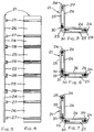
- a kit consists of a plurality of wire mesh panels 20 and a plurality of readily applicable clips 21.
- the panels are all formed with a uniform size mesh 22 adjacent their edges, and the clips each comprise a strip of substantially non-elastic flexible material of a width akin to the mesh size and have a central transverse hinge portion 23, two outer transverse hinge portions 24 that are separated from the central hinge portion by planar intermediate portions 25 each of a length to span at least one mesh, and end portions 26, the intermediate portions and their respective adjacent end portions having mutually-engageable fastening means 27, 28 to enable the outer hinge portions 24 to be secured round mesh wires 29 spaced from edge wires 30 of adjacent panels 20 between which is disposed the central hinge portion 23, as shown in Figures 2 and 5.
- the mutually-engageable fastening means 27, 28 are of the male-and-female snap-fastening type, so as to be disengageable when an assembly formed from wire mesh panels 20 and clips 21 is to be dismantled or modified; thus the male part 27 is shown as being a rib with a bead-like head; and the female part 28 formed by a pair of ribs with mutually facing beads between which the head of the male part snaps into place when the end portion 26 is pressed towards the respective intermediate portion 25.
- the central hinge portion 23 is disposed outwardly with respect to the angle made between the adjacent pair of panels.
- the end portions 26 are of such a length from the outer hinge portions 24 as to be able to extend over the respective edge wires 30 of the adjacent panels, and in Figure 6 the end portions have curved edges 31 to embrace the edge wires, while in Figure 7 the central hinge portion 23 is moulded so as to embrace the edge wires 30.
- the outer hinge portions 24 and/or the central hinge portion 23 may be made thinner (not shown).
- the central hinge portion 23 may be provided with a curvature or bends (not shown) to predetermine an angle between adjacent panels.
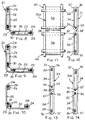
- an alternative form of clip 33 is formed of substantially non-elastic flexible material of a length exceeding twice the mesh pitch of the wire mesh panels 20, each end 34 of each clip being bifurcated over the mid-plane over a length exceeding the mesh pitch and extending from a part-cylindrical inner end 35 adapted to fit closely round an edge wire 30 to claws 36, 37 adapted to embrace the first mesh wire 29 parallel to that edge wire.
- the claws 36, 37 are provided with mutually-engaging fastening means of the male-and-female snap-fastening type as described in relation to the clips 21.
- the material 38 between the part-cylindrical inner ends 35 is made thinner to form a hinge.
- a hollow 39 may be provided between the part-cylindrical inner ends 35.
- the clip 33X shown in Figure 14 has the overall thickness maintained across the portion 40 of the material between the part-cylindrical inner ends 35, so that the clip can be used to connect a pair of adjacent panels in a common plane.
Landscapes
- Engineering & Computer Science (AREA)
- Architecture (AREA)
- Civil Engineering (AREA)
- Structural Engineering (AREA)
- Superconductors And Manufacturing Methods Therefor (AREA)
- Wire Processing (AREA)
- Clamps And Clips (AREA)
- Control Of Motors That Do Not Use Commutators (AREA)
- Fencing (AREA)
- Panels For Use In Building Construction (AREA)
Applications Claiming Priority (2)
| Application Number | Priority Date | Filing Date | Title |
|---|---|---|---|
| GB9805160 | 1998-03-12 | ||
| GBGB9805160.0A GB9805160D0 (en) | 1998-03-12 | 1998-03-12 | Wire mesh assemblies |
Publications (3)
| Publication Number | Publication Date |
|---|---|
| EP0942176A2 true EP0942176A2 (fr) | 1999-09-15 |
| EP0942176A3 EP0942176A3 (fr) | 1999-09-22 |
| EP0942176B1 EP0942176B1 (fr) | 2002-12-04 |
Family
ID=10828358
Family Applications (1)
| Application Number | Title | Priority Date | Filing Date |
|---|---|---|---|
| EP99301623A Expired - Lifetime EP0942176B1 (fr) | 1998-03-12 | 1999-03-04 | Ensemble de treillis de fils |
Country Status (4)
| Country | Link |
|---|---|
| EP (1) | EP0942176B1 (fr) |
| AT (1) | ATE229129T1 (fr) |
| DE (1) | DE69904253D1 (fr) |
| GB (2) | GB9805160D0 (fr) |
Cited By (1)
| Publication number | Priority date | Publication date | Assignee | Title |
|---|---|---|---|---|
| DE102016112075A1 (de) * | 2016-07-01 | 2018-01-04 | Wanzl Metallwarenfabrik Gmbh | Regalsystem |
Family Cites Families (6)
| Publication number | Priority date | Publication date | Assignee | Title |
|---|---|---|---|---|
| GB991580A (en) * | 1962-10-10 | 1965-05-12 | Marmax Horticultural Ltd | Improvements in or relating to protective units for plants |
| GB1254846A (en) * | 1967-12-29 | 1971-11-24 | Power Play Ltd | Improvements in connecting devices |
| US3521332A (en) * | 1968-03-04 | 1970-07-21 | Roy G Kramer | Double ended clip |
| DE3634543A1 (de) * | 1986-10-10 | 1988-04-14 | Richard Krug | Verbindungselement fuer drahtstaender bzw. regale aus gitterfoermigen drahtgeflechten |
| DE4111667C2 (de) * | 1991-04-10 | 2001-03-15 | Hans Lechtenboehmer | Ballfangzaun |
| GB2314833A (en) * | 1996-07-02 | 1998-01-14 | Heartbeat Manufacturing Co The | Containers |
-
1998
- 1998-03-12 GB GBGB9805160.0A patent/GB9805160D0/en not_active Ceased
-
1999
- 1999-03-04 GB GB9904828A patent/GB2335949B/en not_active Expired - Fee Related
- 1999-03-04 AT AT99301623T patent/ATE229129T1/de not_active IP Right Cessation
- 1999-03-04 DE DE69904253T patent/DE69904253D1/de not_active Expired - Lifetime
- 1999-03-04 EP EP99301623A patent/EP0942176B1/fr not_active Expired - Lifetime
Cited By (1)
| Publication number | Priority date | Publication date | Assignee | Title |
|---|---|---|---|---|
| DE102016112075A1 (de) * | 2016-07-01 | 2018-01-04 | Wanzl Metallwarenfabrik Gmbh | Regalsystem |
Also Published As
| Publication number | Publication date |
|---|---|
| GB9904828D0 (en) | 1999-04-28 |
| ATE229129T1 (de) | 2002-12-15 |
| GB9805160D0 (en) | 1998-05-06 |
| EP0942176B1 (fr) | 2002-12-04 |
| EP0942176A3 (fr) | 1999-09-22 |
| GB2335949A (en) | 1999-10-06 |
| DE69904253D1 (de) | 2003-01-16 |
| GB2335949B (en) | 2002-05-01 |
Similar Documents
| Publication | Publication Date | Title |
|---|---|---|
| CA2013501C (fr) | Dispositif de renforcement de conduits a conducteurs electriques et de conduits similaires et collier connexe | |
| USRE38731E1 (en) | Ring binder | |
| KR101245166B1 (ko) | 케이블 트레이 섹션의 연결을 위한 스플라이스 바 | |
| US7810287B2 (en) | Arrangement of elements for producing a panel | |
| US20020186562A1 (en) | Decorative light mounting apparatus | |
| US20200350750A1 (en) | Flexible channel molding assemblies | |
| US4308706A (en) | Support beam for wall or ceiling panels | |
| EP0942176B1 (fr) | Ensemble de treillis de fils | |
| US5084944A (en) | Universal material clip | |
| GB2267605A (en) | Cable tray bridging members | |
| WO2006005339A1 (fr) | Tuile de recouvrement de surfaces | |
| NO165737B (no) | Roeraggregat. | |
| EP0011386B1 (fr) | Clip de montage pour une plaque et leur combinaison | |
| WO2003034561A8 (fr) | Attache de connexion de fils, outil de fixation de corps d'attache et corps d'attache | |
| CA2278625A1 (fr) | Groupe d'elements de construction | |
| US20070063111A1 (en) | Flat flexible cable retainer with undulated surface | |
| CN211526356U (zh) | 灯具安装框 | |
| US6300568B1 (en) | Grommet strip bendable along orthogonally related directions | |
| EP3213984B1 (fr) | Dispositif de garde-boue | |
| US6170223B1 (en) | Panel assembly | |
| EP0191273A1 (fr) | Agrafe d'écartement pour l'assemblage de deux plaques de verre, utilisée en particulier pour des lustres | |
| KR0116931Y1 (ko) | 가설벽체 판넬 | |
| GB2168103A (en) | Tying device | |
| DE60100008D1 (de) | Kabelrinnenabschnitte und daraus hergestellte Kabelrinne durch Verbinbung von mindestens zwei Abschnitten und deren Herstellungsverfahren | |
| AU740131B2 (en) | A ceiling panel and a method of connecting the same |
Legal Events
| Date | Code | Title | Description |
|---|---|---|---|
| PUAI | Public reference made under article 153(3) epc to a published international application that has entered the european phase |
Free format text: ORIGINAL CODE: 0009012 |
|
| PUAL | Search report despatched |
Free format text: ORIGINAL CODE: 0009013 |
|
| AK | Designated contracting states |
Kind code of ref document: A2 Designated state(s): AT BE CH DE DK ES FI FR IE IT LI NL SE |
|
| AX | Request for extension of the european patent |
Free format text: AL;LT;LV;MK;RO;SI |
|
| AK | Designated contracting states |
Kind code of ref document: A3 Designated state(s): AT BE CH CY DE DK ES FI FR GB GR IE IT LI LU MC NL PT SE |
|
| AX | Request for extension of the european patent |
Free format text: AL;LT;LV;MK;RO;SI |
|
| 17P | Request for examination filed |
Effective date: 20000120 |
|
| AKX | Designation fees paid |
Free format text: AT BE CH DE DK ES FI FR IE IT LI NL SE |
|
| RAP1 | Party data changed (applicant data changed or rights of an application transferred) |
Owner name: BEKAERT HANDLING LIMITED |
|
| GRAG | Despatch of communication of intention to grant |
Free format text: ORIGINAL CODE: EPIDOS AGRA |
|
| GRAG | Despatch of communication of intention to grant |
Free format text: ORIGINAL CODE: EPIDOS AGRA |
|
| GRAH | Despatch of communication of intention to grant a patent |
Free format text: ORIGINAL CODE: EPIDOS IGRA |
|
| 17Q | First examination report despatched |
Effective date: 20020604 |
|
| GRAH | Despatch of communication of intention to grant a patent |
Free format text: ORIGINAL CODE: EPIDOS IGRA |
|
| GRAA | (expected) grant |
Free format text: ORIGINAL CODE: 0009210 |
|
| AK | Designated contracting states |
Kind code of ref document: B1 Designated state(s): AT BE CH DE DK ES FI FR IE IT LI NL SE |
|
| PG25 | Lapsed in a contracting state [announced via postgrant information from national office to epo] |
Ref country code: NL Free format text: LAPSE BECAUSE OF FAILURE TO SUBMIT A TRANSLATION OF THE DESCRIPTION OR TO PAY THE FEE WITHIN THE PRESCRIBED TIME-LIMIT Effective date: 20021204 Ref country code: LI Free format text: LAPSE BECAUSE OF FAILURE TO SUBMIT A TRANSLATION OF THE DESCRIPTION OR TO PAY THE FEE WITHIN THE PRESCRIBED TIME-LIMIT Effective date: 20021204 Ref country code: IT Free format text: LAPSE BECAUSE OF FAILURE TO SUBMIT A TRANSLATION OF THE DESCRIPTION OR TO PAY THE FEE WITHIN THE PRESCRIBED TIME-LIMIT;WARNING: LAPSES OF ITALIAN PATENTS WITH EFFECTIVE DATE BEFORE 2007 MAY HAVE OCCURRED AT ANY TIME BEFORE 2007. THE CORRECT EFFECTIVE DATE MAY BE DIFFERENT FROM THE ONE RECORDED. Effective date: 20021204 Ref country code: FI Free format text: LAPSE BECAUSE OF FAILURE TO SUBMIT A TRANSLATION OF THE DESCRIPTION OR TO PAY THE FEE WITHIN THE PRESCRIBED TIME-LIMIT Effective date: 20021204 Ref country code: CH Free format text: LAPSE BECAUSE OF FAILURE TO SUBMIT A TRANSLATION OF THE DESCRIPTION OR TO PAY THE FEE WITHIN THE PRESCRIBED TIME-LIMIT Effective date: 20021204 Ref country code: BE Free format text: LAPSE BECAUSE OF FAILURE TO SUBMIT A TRANSLATION OF THE DESCRIPTION OR TO PAY THE FEE WITHIN THE PRESCRIBED TIME-LIMIT Effective date: 20021204 Ref country code: AT Free format text: LAPSE BECAUSE OF FAILURE TO SUBMIT A TRANSLATION OF THE DESCRIPTION OR TO PAY THE FEE WITHIN THE PRESCRIBED TIME-LIMIT Effective date: 20021204 |
|
| REF | Corresponds to: |
Ref document number: 229129 Country of ref document: AT Date of ref document: 20021215 Kind code of ref document: T |
|
| REG | Reference to a national code |
Ref country code: CH Ref legal event code: EP |
|
| REG | Reference to a national code |
Ref country code: IE Ref legal event code: FG4D |
|
| REF | Corresponds to: |
Ref document number: 69904253 Country of ref document: DE Date of ref document: 20030116 |
|
| PG25 | Lapsed in a contracting state [announced via postgrant information from national office to epo] |
Ref country code: SE Free format text: LAPSE BECAUSE OF FAILURE TO SUBMIT A TRANSLATION OF THE DESCRIPTION OR TO PAY THE FEE WITHIN THE PRESCRIBED TIME-LIMIT Effective date: 20030304 Ref country code: IE Free format text: LAPSE BECAUSE OF NON-PAYMENT OF DUE FEES Effective date: 20030304 Ref country code: DK Free format text: LAPSE BECAUSE OF FAILURE TO SUBMIT A TRANSLATION OF THE DESCRIPTION OR TO PAY THE FEE WITHIN THE PRESCRIBED TIME-LIMIT Effective date: 20030304 |
|
| PG25 | Lapsed in a contracting state [announced via postgrant information from national office to epo] |
Ref country code: DE Free format text: LAPSE BECAUSE OF FAILURE TO SUBMIT A TRANSLATION OF THE DESCRIPTION OR TO PAY THE FEE WITHIN THE PRESCRIBED TIME-LIMIT Effective date: 20030305 |
|
| NLV1 | Nl: lapsed or annulled due to failure to fulfill the requirements of art. 29p and 29m of the patents act | ||
| REG | Reference to a national code |
Ref country code: CH Ref legal event code: PL |
|
| PG25 | Lapsed in a contracting state [announced via postgrant information from national office to epo] |
Ref country code: ES Free format text: LAPSE BECAUSE OF FAILURE TO SUBMIT A TRANSLATION OF THE DESCRIPTION OR TO PAY THE FEE WITHIN THE PRESCRIBED TIME-LIMIT Effective date: 20030627 |
|
| ET | Fr: translation filed | ||
| PLBE | No opposition filed within time limit |
Free format text: ORIGINAL CODE: 0009261 |
|
| STAA | Information on the status of an ep patent application or granted ep patent |
Free format text: STATUS: NO OPPOSITION FILED WITHIN TIME LIMIT |
|
| 26N | No opposition filed |
Effective date: 20030905 |
|
| REG | Reference to a national code |
Ref country code: IE Ref legal event code: MM4A |
|
| PGFP | Annual fee paid to national office [announced via postgrant information from national office to epo] |
Ref country code: FR Payment date: 20061215 Year of fee payment: 9 |
|
| REG | Reference to a national code |
Ref country code: FR Ref legal event code: ST Effective date: 20081125 |
|
| PG25 | Lapsed in a contracting state [announced via postgrant information from national office to epo] |
Ref country code: FR Free format text: LAPSE BECAUSE OF NON-PAYMENT OF DUE FEES Effective date: 20080331 |