EP0942178A2 - Dispositif pour l'ancrage autobloquant d'éléments de construction - Google Patents
Dispositif pour l'ancrage autobloquant d'éléments de construction Download PDFInfo
- Publication number
- EP0942178A2 EP0942178A2 EP99250012A EP99250012A EP0942178A2 EP 0942178 A2 EP0942178 A2 EP 0942178A2 EP 99250012 A EP99250012 A EP 99250012A EP 99250012 A EP99250012 A EP 99250012A EP 0942178 A2 EP0942178 A2 EP 0942178A2
- Authority
- EP
- European Patent Office
- Prior art keywords
- capsule
- anchor
- armature
- chemicals
- anchoring
- Prior art date
- Legal status (The legal status is an assumption and is not a legal conclusion. Google has not performed a legal analysis and makes no representation as to the accuracy of the status listed.)
- Granted
Links
- 239000002775 capsule Substances 0.000 claims abstract description 129
- 239000000126 substance Substances 0.000 claims abstract description 82
- 238000006243 chemical reaction Methods 0.000 claims abstract description 38
- 238000004873 anchoring Methods 0.000 claims abstract description 34
- 239000000376 reactant Substances 0.000 claims abstract description 21
- 238000005520 cutting process Methods 0.000 claims description 17
- 238000005192 partition Methods 0.000 claims description 17
- 238000013461 design Methods 0.000 claims description 10
- 239000002360 explosive Substances 0.000 claims description 10
- 241000894006 Bacteria Species 0.000 claims description 6
- 238000002156 mixing Methods 0.000 claims description 3
- 238000005530 etching Methods 0.000 claims description 2
- 230000005021 gait Effects 0.000 claims description 2
- 239000003999 initiator Substances 0.000 claims description 2
- 244000005700 microbiome Species 0.000 claims description 2
- 230000003213 activating effect Effects 0.000 claims 1
- 238000007711 solidification Methods 0.000 claims 1
- 230000008023 solidification Effects 0.000 claims 1
- 230000000694 effects Effects 0.000 abstract description 6
- 239000000243 solution Substances 0.000 description 16
- 239000002585 base Substances 0.000 description 14
- 239000000853 adhesive Substances 0.000 description 7
- 230000001070 adhesive effect Effects 0.000 description 7
- 239000000463 material Substances 0.000 description 7
- 239000003566 sealing material Substances 0.000 description 7
- 239000000945 filler Substances 0.000 description 6
- 230000015572 biosynthetic process Effects 0.000 description 5
- 150000001875 compounds Chemical class 0.000 description 5
- 239000002253 acid Substances 0.000 description 4
- 238000009412 basement excavation Methods 0.000 description 4
- 239000000057 synthetic resin Substances 0.000 description 4
- 229920003002 synthetic resin Polymers 0.000 description 4
- 230000008901 benefit Effects 0.000 description 3
- 239000003518 caustics Substances 0.000 description 3
- 238000003780 insertion Methods 0.000 description 3
- 230000037431 insertion Effects 0.000 description 3
- 238000004519 manufacturing process Methods 0.000 description 3
- 238000000034 method Methods 0.000 description 3
- 239000004570 mortar (masonry) Substances 0.000 description 3
- 230000000149 penetrating effect Effects 0.000 description 3
- 239000004033 plastic Substances 0.000 description 3
- 230000008569 process Effects 0.000 description 3
- 238000009991 scouring Methods 0.000 description 3
- 239000002689 soil Substances 0.000 description 3
- 239000007787 solid Substances 0.000 description 3
- 238000010521 absorption reaction Methods 0.000 description 2
- 150000007513 acids Chemical class 0.000 description 2
- 238000013459 approach Methods 0.000 description 2
- 239000003795 chemical substances by application Substances 0.000 description 2
- 238000005516 engineering process Methods 0.000 description 2
- 239000011521 glass Substances 0.000 description 2
- 230000035515 penetration Effects 0.000 description 2
- 239000011435 rock Substances 0.000 description 2
- 239000002904 solvent Substances 0.000 description 2
- 238000012549 training Methods 0.000 description 2
- XLYOFNOQVPJJNP-UHFFFAOYSA-N water Substances O XLYOFNOQVPJJNP-UHFFFAOYSA-N 0.000 description 2
- 229910000831 Steel Inorganic materials 0.000 description 1
- 230000001944 accentuation Effects 0.000 description 1
- 230000006978 adaptation Effects 0.000 description 1
- 230000032683 aging Effects 0.000 description 1
- 239000003708 ampul Substances 0.000 description 1
- 239000004568 cement Substances 0.000 description 1
- 230000008859 change Effects 0.000 description 1
- 239000002131 composite material Substances 0.000 description 1
- 239000007884 disintegrant Substances 0.000 description 1
- 238000009826 distribution Methods 0.000 description 1
- 239000006260 foam Substances 0.000 description 1
- 230000000977 initiatory effect Effects 0.000 description 1
- 238000002347 injection Methods 0.000 description 1
- 239000007924 injection Substances 0.000 description 1
- 230000007774 longterm Effects 0.000 description 1
- 239000000203 mixture Substances 0.000 description 1
- 238000012986 modification Methods 0.000 description 1
- 230000004048 modification Effects 0.000 description 1
- 239000004848 polyfunctional curative Substances 0.000 description 1
- 238000003825 pressing Methods 0.000 description 1
- 238000007639 printing Methods 0.000 description 1
- 239000010453 quartz Substances 0.000 description 1
- 230000035484 reaction time Effects 0.000 description 1
- 239000011347 resin Substances 0.000 description 1
- 229920005989 resin Polymers 0.000 description 1
- 238000007142 ring opening reaction Methods 0.000 description 1
- 238000010008 shearing Methods 0.000 description 1
- VYPSYNLAJGMNEJ-UHFFFAOYSA-N silicon dioxide Inorganic materials O=[Si]=O VYPSYNLAJGMNEJ-UHFFFAOYSA-N 0.000 description 1
- 239000010959 steel Substances 0.000 description 1
- 230000008719 thickening Effects 0.000 description 1
- 238000012546 transfer Methods 0.000 description 1
Images


Classifications
-
- F—MECHANICAL ENGINEERING; LIGHTING; HEATING; WEAPONS; BLASTING
- F16—ENGINEERING ELEMENTS AND UNITS; GENERAL MEASURES FOR PRODUCING AND MAINTAINING EFFECTIVE FUNCTIONING OF MACHINES OR INSTALLATIONS; THERMAL INSULATION IN GENERAL
- F16B—DEVICES FOR FASTENING OR SECURING CONSTRUCTIONAL ELEMENTS OR MACHINE PARTS TOGETHER, e.g. NAILS, BOLTS, CIRCLIPS, CLAMPS, CLIPS OR WEDGES; JOINTS OR JOINTING
- F16B13/00—Dowels or other devices fastened in walls or the like by inserting them in holes made therein for that purpose
- F16B13/14—Non-metallic plugs or sleeves; Use of liquid, loose solid or kneadable material therefor
- F16B13/141—Fixing plugs in holes by the use of settable material
- F16B13/143—Fixing plugs in holes by the use of settable material using frangible cartridges or capsules containing the setting components
-
- F—MECHANICAL ENGINEERING; LIGHTING; HEATING; WEAPONS; BLASTING
- F16—ENGINEERING ELEMENTS AND UNITS; GENERAL MEASURES FOR PRODUCING AND MAINTAINING EFFECTIVE FUNCTIONING OF MACHINES OR INSTALLATIONS; THERMAL INSULATION IN GENERAL
- F16B—DEVICES FOR FASTENING OR SECURING CONSTRUCTIONAL ELEMENTS OR MACHINE PARTS TOGETHER, e.g. NAILS, BOLTS, CIRCLIPS, CLAMPS, CLIPS OR WEDGES; JOINTS OR JOINTING
- F16B13/00—Dowels or other devices fastened in walls or the like by inserting them in holes made therein for that purpose
- F16B13/14—Non-metallic plugs or sleeves; Use of liquid, loose solid or kneadable material therefor
- F16B13/141—Fixing plugs in holes by the use of settable material
- F16B13/143—Fixing plugs in holes by the use of settable material using frangible cartridges or capsules containing the setting components
- F16B13/144—Fixing plugs in holes by the use of settable material using frangible cartridges or capsules containing the setting components characterised by the shape or configuration or material of the frangible cartridges or capsules
Definitions
- the invention relates to a device for self-anchoring components in the receiving openings provided for this purpose, by inserting the anchoring element placed in the receiving opening in an anchoring position and in the opening looking horizontal and vertical with the walls of the receiving opening for receiving Strictly connecting forces.
- DE A1 26 25 492 discloses an arrangement for fastening a dowel. According to the document, a synthetic resin layer is arranged between the inner wall of the dowel hole and an inserted dowel. After the synthetic resin has hardened, the dowel is glued into the hole and firmly anchored. The solution has the disadvantage that the introduction of the adhesive is very complicated.
- DE 195 52 712 A1 discloses a mortar cartridge.
- the cartridge is inserted into a hole to be made precisely and is filled with a plastic mortar. It is closed on its upper side.
- the closure part for this purpose carries a guide for inserting an armature, which is centered between guide ribs and is guided axially in the cartridge. Due to the pressure of the mortar, which increases when the anchor is inserted, the cartridge wall is pressed against the bore wall and creates a non-positive connection between the walls.
- the solution according to the invention is disadvantageous in that the absorbed forces are very low.
- DE A1 22 22 013 discloses a two-component adhesive cartridge. The cartridge is inserted into a borehole and has helical grooves on its inner wall.
- a container coated with thin plastic is inserted, which contains chemicals that react with one another.
- the anchor is inserted into the cartridge, the container is destroyed, the chemicals react and the anchor is held in the cartridge.
- the pressure of the anchor screwed into the helix displaces the reacting chemicals, increases the pressure in the cartridge and creates a non-positive connection between the outer wall and the inner wall of the bore.
- the type of connection is complex and, due to its multi-part arrangement, also confusing.
- EP 661 463 A1 follows a similar, almost identical arrangement.
- the document specifies a composite anchor consisting of an anchor rod and a cartridge which can be destroyed by the anchor rod, an inner container having an inner container which is distributed over the length of the cartridge and is delimited from one another and can be destroyed one after the other when the anchor rod is driven in.
- the individual sections have different volumes and are designed in such a way that they break apart one after the other from the ends of the inner container to the center and release the water in the respective inner container to the environment. This achieves the driving-in and mixing process as well as better fastening.
- the solution according to the invention has the disadvantage that a holding medium is a dry medium which only reacts to a certain pastosity and later firmness when it is added and mixed with water.
- DE 27 05 484 A1 discloses an anchor attachment with a two-component adhesive cartridge.
- the anchor attachment consists of an inner and outer ampoule, in which the respective component of a two-component adhesive is contained separately from each other. This adhesive is used to fasten an anchor in a borehole. Quartz sands are contained in the adhesive as a filler. The hardener component and the filler, originally placed in a separate room, put in contact, react hardening and connect the anchor to the outer hole.
- EP 597 217 A1 discloses a solution similar to this. Here the cartridge with tixotropic substances is made of glass.
- DE 32 02 541 A1 presents an injection anchor for insertion into a structural bore, which is then pressed with a hardening filling compound through a channel that extends over the entire length of the anchor.
- the armature has a continuously extending, chamber-forming partition and a plug for closing off the bore.
- the partition has a profile which is S-shaped in cross section and is inserted into a uniformly shaped trough and brought into connection with the filling compound.
- a disadvantage of the solution according to the invention can be seen in the fact that the hardening filler compound probably connects the bore wall and the anchor, but must be pressed separately after the anchor has been inserted into the bore. At the same time, the degree of filling of the cavity in the bore can only be determined when the filling compound is visibly emerging at an outlet opening.
- EP 0 251 999 A1 discloses an anchor rod that can be anchored by means of hardenable masses.
- the anchor rod is pressed into a hardening mass which is already inserted into a bore and is put under pressure by the anchor rod, fills the spaces between the anchor rod and the inner wall of the bore and, after hardening, connects the fixtures in a form-fitting manner.
- the form fit is further improved by the fact that an undercut is present in the upper region of the anchor rod, which underfilled by the mass allows an additional strength effect to be achieved.
- DE 35 35 251 A1 presents a sleeve-shaped dowel body which consists of one or more shaft sleeves which are put together in a desired length.
- the rear shaft sleeve has a head piece and centers the sleeve and the anchor to be inserted later.
- a closure piece is arranged on the floor and prevents the fillers from leaving the dowel in an uncontrolled manner.
- the dowel body enables optimal control of the degree of filling with the filler and the avoidance of incorrect manipulation.
- the lattice-like design of the dowel body makes it possible for the filler, penetrating the dowel body, to bond intensively to the inner wall of the bore.
- DE 37 27 154 A1 has a threaded bolt intended for use as an anchor. According to this document, a threaded bolt for a form-fitting anchoring is presented, which has an extension forming an undercut surface.
- DE 41 31 457 A1 presents a cartridge or cartridge for chemical fastening technology that can be used for several solutions mentioned in the prior art.
- the cartridge can be used as an outer or inner cartridge and contains a two-component adhesive of a radically curable synthetic resin and a spatially separate hardening agent for the synthetic resin.
- the cartridge is sealed, inserted into a borehole, an anchor rod is driven into the borehole, the walls of the cartridge being destroyed, the resin penetrating into the cavities between the anchor wall and the bore, gelling after three to four minutes and strength after a total hardening time of thirty minutes of 100 kN.
- the invention has for its object a device for self-locking anchoring of components in the receiving openings provided for this purpose, which are introduced by means of insertion of the anchoring element is brought into an anchoring position in the receiving opening and in the opening with the walls of the receiving opening for receiving of horizontally and vertically acting forces, which creates it enables a full-surface, self-organizing connection between the holding element and wall of the opening to allow complex forces to be absorbed, and the mechanical effort for establishing the connection between the structural and holding element and reduce base body.
- an anchor capsule has chambers formed by a partition in which chemicals and reactants are stored separately from one another and an anchor inserted into the anchor capsule is held in a central position of the center axis of the anchor capsule and has cutting means for destroying the partition, the chemicals are mixed and brought to reaction, in particular curing, and predetermined breaking points are provided in the anchor capsule for the reaction chemicals to pass through to fill a cavity.
- a compact body is formed which connects the walls of the cavity and the anchor in a force-fitting and form-fitting manner.
- the invention is sensibly designed if cutting means, radially opposite one another, arranged on the shaft of the armature, projecting like a flag, wedge-shaped, with the cutting edge following the wedge shape outwards, with their extension projecting beyond the radial extension of the partition wall.
- the invention obtains an advantageous embodiment in that the length of the armature is equal to the inner length of the armature capsule, and the flange of the armature has a larger diameter than the outer outer extent of the armature capsule.
- One embodiment of the invention is given in that the predetermined breaking points are thinned to 0.01 to 0.5 mm with respect to the wall thickness of the outer wall of the anchor capsule and distributed in vertical and radial intervals, are arranged in the anchor capsule.
- the anchor has a point at its front end over which a groove of the shaft is arranged.
- the invention is advantageously designed if the armature is continuously wrapped with a helix which has a cutting edge at its front helix beginning facing the armature tip, which protrudes beyond the partition wall in the initial helix course and the helix has a radially extending, flat gait profile.
- An embodiment of the invention presents itself when the anchor has a greater longitudinal extension of its shaft than the length of the anchor capsule and, when fully inserted into the capsule, its front part extends beyond the base of the capsule.
- the embodiment of the invention follows in that the anchor capsule is connected to a further anchor capsule and the anchor capsules connected in this way are shielded from one another at their connection point.
- the shield is formed from a pressure plate which covers the capsule, which is formed from a plurality of concentrically mutually adjacent chambers, in the sense of the invention at least three chambers, the two inner chambers in the formation and location resemble the chambers of the upper capsule part, which contain the chemicals which are concentrically enclosed by the outer third chamber.
- the outer chamber is filled with a reactant which penetrates the predetermined breaking points of the capsule, the pressure plate separating the capsule having reaction elements directed against the reactant, which are distributed in a ring on the pressure plate.
- the pressure plate has pragmatically central predetermined breaking points in the invention.
- the reactants are formed from an explosive. It is also possible to form these agents from a dissolving substance which dissolves the predetermined breaking points and the base material or an etching substance can be formed which, after initiation, opens the predetermined breaking points in a caustic manner and expands the bore wall.
- the reactant can be formed from a bacterium, a detonator being a reaction element for the explosive, a chemical initiator for the dissolving substance, and the bacteria being reacted with a substance which activates the microorganisms.
- the invention is further shaped when the capsule sequence is alternately formed in a direct change, upper and lower capsule, or in a non-alternating sequence.
- the flange can have a stop means on its upper side.
- an anchoring element is formed from a cylindrical capsule which has a closed bottom at the lower end and is open at the upper end, the cylindrical capsule enclosing with its outer wall two concentrically formed inner chambers which are separated from each other by a thin partition. At least two chemicals are arranged in the chambers, one of which reacts independently or independently with the other when they are brought together.
- the outer wall of the anchor capsule is provided with predetermined breaking points which, when subjected to loads of a specified size, form openings in the cylinder wall.
- the device is completed by an anchor, which can be guided in the axial direction through a closure opening of the anchor capsule into the interior.
- Separating blades arranged on the shaft of the armature are tapered conically to the tip of the armature and, in their greatest extent, protrude beyond the partition walls which run concentrically in the interior of the armature capsule.
- the conical arrangement advantageously allows, together with the sealing material at the opening of the anchor capsule, a precise centering of the anchor in the capsule and its concentric course on the longitudinal center axis.
- the dividing blades cut the dividing walls. This brings the chemicals together and causes them to react.
- the volume of the armature displaces the reacting chemicals which emerge through the now increased pressure through the predetermined breaking points of the capsule wall and penetrate into the cavities between the bore and the capsule.
- the device is inextricably linked to the structure or other solid base.
- the connection is positive and non-positive because the bore walls are not flat, but at least have high roughness depths, and the shaft of the anchor has constrictions that establish a positive connection between the bore walls and the shaft of the anchor.
- the anchor does not have triangular, radially projecting cutting edges, but rather surrounds the anchor shaft a leaf-shaped helix that ends near the anchor tip in a cutting edge that is able to close the partition in the anchor capsule cut.
- the anchor is now inserted into the anchor capsule by means of a rotary movement.
- the chemicals are designed so that they do not form a firm connection with the blade surfaces of the coil and the shaft.
- the anchor is set in an advantageous embodiment of the invention in a rotation directed against the screwing movement and can now be unscrewed from the hardened chemical mass of the device or turned further.
- the invention provides a further advantageous solution if the capsule is divided into two capsule parts running transversely to the longitudinal axis.
- the upper part of the capsule contains a chamber with the same configuration as the homogeneous anchor capsule already shown according to the invention.
- the second lower chamber of the anchor capsule has the same outer diameter as the upper part and fulfills the conditions of the continuous cylindrical shape of the complex anchor capsule. Both chambers of the capsule are separated by a pressure plate.
- the lower chamber carries a further advantageously concentrically formed chamber in which reactants are formed, which act on the materials of the bore of the structure or of the base body. According to the invention, various types of disintegrants as well as acids, bases and solvent substances as well as bacteria reacting for specially selected materials are to be used as reactants.
- the reactants here the specified explosives
- the pressure of the armature is generated in that in the upper chamber the reaction of the chemicals is completed in a first stage and the armature can generate twisting forces which move the pressure plate in the direction of the capsule bottom.
- the explosive In the case of the explosive, it detonates in a short violent blow, which affects the strength and homogeneity of the walls of the bore at the height of the capsule part. Acids and bases as caustic and also solvent substances can react in their typical properties. In selected application examples, bacteria as long-term reactants are suitable according to the invention for the piston-like formation of the undercut. To trigger such reactions, the armature is now rotated concentrically by the pressure plate into the second capsule chamber and triggers the reaction of the chemicals that harden.
- the chemicals of the device get into the cylindrical part of the bore, which has now been decolourized by the reactants, fill the now larger diameter and form a piston-like thickening in the undercut.
- the grading of the anchor capsule with several chambers can be continued alternately in order to be able to cope with the greatest loads, especially tensile loads. It is also possible to design the excess length of the armature and to guide it through the chamber parts of the capsule into an open part of the bore.
- the solution according to the invention has the advantage that the device for the self-retaining anchoring of components can be designed in a variety of ways in the receiving openings provided therefor.
- reaction masses that react chemically, increase their volume and harden with high strength values make it possible to create a self-retaining anchor in existing or specially created openings.
- the formation of a combined form of the anchors allows the absorption of large forces, especially in the case of a large-sized design of the anchoring arrangement. This is advantageously possible primarily by the fact that by adding a second anchor capsule to the underside of the normal capsule, a excavation is carried out in the lower region of the bore, which is present as a cylindrical cavity, and the absorption of larger forces is possible because this excavation after it is produced by the reaction substance, filled by the self-curing chemicals and the enlargement of the lower part of the bore as an undercut makes it completely impossible for the anchoring element to slide out of the bore.
- the scouring can advantageously be produced by reaction substances such as explosives, caustic and dissolving substances and in extreme cases by bacteria.
- reaction substances such as explosives, caustic and dissolving substances and in extreme cases by bacteria.
- the selection of the reaction substances depends on the material of the anchoring base and on the available exposure time of the reaction substance.
- an explosive is of course advantageously selected which explodes the surrounding base by ignition with the pressure plate, enlarges the available cavity and thereby allows an effective increase in the volume of the solidified chemicals.
- the expansion of the lower part of the anchoring produced in the lower part of the bore, as already illustrated, then no longer allows the anchoring to slide out of the opening without destroying the anchoring arrangement.
- the self-reacting dowel connection for very small-sized connecting elements, such as holding pictures in building walls, because a simple and inexpensive technology is necessary.
- the adjustment can be made not only in size, but in particular is possible in that the materials of the anchor and the anchor capsule can be changed. Glass, plastic and steel can be used.
- the anchor shapes can be varied. In particular, however, a wide range of variations in the field of chemical composition is possible, which determine the substances that are necessary for the reaction of filling cavities of the anchor capsule and the bore and are ultimately responsible for the high resilience of the device for anchoring. It is therefore effective not only to react two chemicals for hardening and increase in volume, but it is also conceivable to use significantly more than two chemicals for the reaction in order to deliberately determine certain strengths, reaction time, contact pressure and fillability of the cavities by the reacted chemicals to reach.
- the explosive When introduced into the anchoring opening, the explosive has a smashing effect and a decomposing acid, whereby the reverse order of reaction is also possible.
- the steps in the anchor capsule which together form a cylindrical shape of the overall anchor
- by introducing initial ignitions from the outside in the case of primarily large-sized anchoring devices, a varied modification of the anchoring wall of the bore can be achieved.
- cams are arranged alternately with the predetermined breaking points in the inner surfaces of the anchor capsule, which in particular when using the anchor capsule for a helically designed anchor, which dissolves with the surfaces due to a rotary movement in the hardened chemicals can move axially, the hardened filling is supported against twisting in the capsule.
- the cams secure an axial and radial locking in the capsule, especially since the reacted chemicals have penetrated the predetermined breaking points, filled the cavity between the capsule and the wall of the bore and created a forceful and form-fitting, complex connection of the entire device. This is advantageous if load elements are arranged on the armature, which enter an increasing load into the device.
- Fig. 1 shows the device in a cavity 9 with the diameter d1, the one Bore or an opening can be and corresponds to the length L of an anchor capsule 2.
- the anchor capsule 2 has the diameter d and is inserted to the bottom of the cavity 9. It is appropriate that the difference between d and d1 is small, the larger To avoid gaps.
- the outer wall of the anchor capsule 2 is with predetermined breaking points 22 provided, arranged in the longitudinal and transverse directions of the wall of the anchor capsule 2 are.
- An inner chamber 3 and an outer chamber 4 are concentric in the anchor capsule 2 classified. Chemicals C1; C2 are contained in the chambers 3; 4 and by a Partition 5 separated so that the chemicals are not brought together and cannot react with each other in an uncontrolled manner.
- An anchor 1 is provided, which overlaps the longitudinal center axis of the anchor capsule 2 is movable.
- the anchor 1 is largely symmetrical, being on his Circumference at least two cutting edges 6, advantageously opposite one another, are arranged.
- the cutting edges 6 are located in the front area of the shaft the anchor capsule 2 via constrictions 8, which in a tip 7 of the shaft of the anchor 1st pass over.
- the cutting edges 6 protrude with their outer cutting ends over the partition 5 beyond.
- the anchor 1 is introduced into a sealing material which is arranged at the opening of the anchor capsule 2, closing it.
- the sealing material 11 is annular and its ring opening is adapted to the size of the shaft of the armature 1.
- the armature 1 is inserted into the ring-shaped opening of the sealing material and its tip 7 is moved along the longitudinal center axis of the armature capsule 2 towards the bottom of the armature capsule 2.
- the separating cutters 6 cut through the soft sealing material 11 and, in the event of further movement, the dividing wall 5 between the chambers 3; 4. This brings together chemicals C1, C2 and can react as intended.
- the first desired reaction is to increase the total volume of the chemicals.
- the anchor 1 With its own volume displaces the chemicals C1; C2 and puts pressure in the capsule 2. These press through the predetermined breaking points 22 into the cavity 9 and fill in the difference between d and d1. To catch the pressure that would press the reacting chemicals C1; C2 out of the upper opening of the anchor capsule 2, the anchor 1 is provided with a flange 10, which now covers and closes the opening after the anchor 1 has been pressed in completely. The anchor 1 is additionally supported by the constrictions 8 on the shaft of the anchor 1, into which the expanding chemicals C1; C2 penetrate.
- the reaction rate can be achieved by a corresponding classification of the chemicals C1; C2, after which the mixed chemicals harden and now connect to the armature 1 in a non-positive and positive manner by adaptation to the surface structure of the cavity 9.
- suitable connecting elements can be arranged at the head end of the armature 1 in the region of the flange 10, which allow a sensible connection for absorbing horizontal and vertical forces and their components.
- FIG. 1 The figuration of the device according to FIG. 1 shows that an inseparable connection between the base and anchor capsule 2 via the cavity 9 and the anchor 1 has been achieved.
- This can be unfavorable in applications, so that the invention in FIG. 2 presents a variation that allows a detachable connection of the armature 1.
- a helix 14 has been chosen, which wraps flatly around the shaft of the armature 1.
- the helix 14 has a cutting edge 15 in the front area, which cuts through the partition 5 of the chambers 3, 4 in the manner shown in FIG.
- the reaction of the chemicals C1; C2 and the production of the holding function of the device takes place analogously to the process in FIG. 1.
- FIG. 3 presents a variation of the design according to FIG. 2.
- the cavity 9 extends over the length 13 and is not filled by the anchor capsule 2.
- a tension force can be generated in the attached element and the tension can be increased as desired with multiple rotations. This is particularly noticeable when the fastening device for holding tension, such as the rope tension of masts, cable cars or the like. Facilities to be used.
- a corresponding stop means 24 is arranged on the top of the flange 10.
- Fig. 4 shows the arrangement similar to Figures 1 and 2, but here the anchor capsule 2 is formed in two stages.
- the anchor capsule 2 carries in its lower region a further anchor capsule 2 ′, which has an annular chamber 20 concentrically in its outer region, in which a reactant 17 is embedded.
- the upper part of the capsule 2 is equivalent to that of the capsule 2 according to FIG. 2.
- a pressure plate 18 is arranged between the anchor capsules 2; 2 'and carries in its outer regions reaction elements 19 which are directed towards the chamber 20.
- the functional classification of the anchor capsules 2; 2 'now takes place in two stages.
- the anchor 1 is introduced into the anchor capsule 2 in the manner already illustrated and, after reaching the pressure plate 18, causes the chemicals C1; C2 to react in depth L1.
- the pressure plate 18 is not loaded by the armature 1.
- the armature 1 is rotated and presses the pressure plate 18 onto the chamber 20.
- the reaction elements 19 activate the reactant 17 in the chamber 20, which causes the scouring 16 over the length L2, the cavity 9 now being enlarged by the difference from d1 to d2.
- the scouring 16 is created and by the penetration of the armature 1 beyond the pressure plate 18. This initiates the reaction of the chemicals C1; C2 in the anchor capsule 2 ', in the course of which the chemicals C1; C2 penetrate into the excavation 16 when they increase or decrease their volume, generate a piston-like enlargement and then harden.
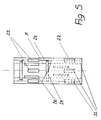
- the anchor 1 according to FIG. 2 can be used. It is of course possible to set the configuration according to FIG. 4 so that the anchor 1 according to FIG. 1 can be used. Designing, and here the person skilled in the art sees the invention embodied, the anchor capsule 2 ′ can be formed several times in steps in order to produce a plurality of depressions 16. It is furthermore in accordance with the invention to transfer the design according to FIG. 3 with an extended anchor 1 to the design according to FIG. 4. 5 shows a design of the anchor capsule 2. In the anchor capsule 2, horizontally and vertically running predetermined breaking points 22 are arranged. The inner surfaces 25 of the anchor capsule 2 carry cams 26, 27 which are intended to prevent the positive and positive connection on the walls of the capsule 2 from rotating and shearing off independently and are suitable for introducing greater axial tensile forces into the anchor.
Landscapes
- Engineering & Computer Science (AREA)
- General Engineering & Computer Science (AREA)
- Mechanical Engineering (AREA)
- Joining Of Building Structures In Genera (AREA)
- Piles And Underground Anchors (AREA)
- Valve Device For Special Equipments (AREA)
- Electronic Switches (AREA)
Applications Claiming Priority (2)
| Application Number | Priority Date | Filing Date | Title |
|---|---|---|---|
| DE19802185 | 1998-01-16 | ||
| DE19802185A DE19802185A1 (de) | 1998-01-16 | 1998-01-16 | Selbsthalteanker (SEHA) |
Publications (3)
| Publication Number | Publication Date |
|---|---|
| EP0942178A2 true EP0942178A2 (fr) | 1999-09-15 |
| EP0942178A3 EP0942178A3 (fr) | 1999-11-24 |
| EP0942178B1 EP0942178B1 (fr) | 2004-09-22 |
Family
ID=7855257
Family Applications (1)
| Application Number | Title | Priority Date | Filing Date |
|---|---|---|---|
| EP99250012A Expired - Lifetime EP0942178B1 (fr) | 1998-01-16 | 1999-01-15 | Dispositif pour l'ancrage autobloquant d'éléments de construction |
Country Status (3)
| Country | Link |
|---|---|
| EP (1) | EP0942178B1 (fr) |
| AT (1) | ATE277292T1 (fr) |
| DE (3) | DE19802185A1 (fr) |
Cited By (2)
| Publication number | Priority date | Publication date | Assignee | Title |
|---|---|---|---|---|
| JP2010222968A (ja) * | 2009-03-23 | 2010-10-07 | Hilti Ag | 連結装置および連結を形成する方法 |
| EP3557085A1 (fr) * | 2018-04-17 | 2019-10-23 | Colux GmbH | Agencement de cheville |
Citations (11)
| Publication number | Priority date | Publication date | Assignee | Title |
|---|---|---|---|---|
| DE1952712A1 (de) | 1964-01-29 | 1971-05-06 | Rudolf Wolter | Moertelpatrone |
| DE2222013A1 (de) | 1972-05-05 | 1973-11-22 | Upat Max Langensiepen Kg | Zweikomponentenkleber-patrone |
| DE2625492A1 (de) | 1976-06-05 | 1977-12-15 | Josef Buchholz | Anordnung zum befestigen eines duebels |
| DE2705484A1 (de) | 1977-02-10 | 1978-08-17 | Upat Max Langensiepen Kg | Ankerbefestigung mit einer zweikomponentenkleber-patrone |
| DE3202541A1 (de) | 1982-01-27 | 1983-08-04 | Kremo Werke Hermanns Gmbh & Co Kg, 4150 Krefeld | Injektionsanker |
| DE3535251A1 (de) | 1985-10-03 | 1987-04-09 | Hilti Ag | Huelsenfoermiger duebelkoerper |
| EP0251999A1 (fr) | 1986-06-23 | 1988-01-07 | HILTI Aktiengesellschaft | Boulon d'ancrage pour être ancré au moyen d'une matière trempante |
| DE3727154A1 (de) | 1987-08-14 | 1989-02-23 | Heinrich Liebig | Fuer den einsatz als klebeanker bestimmter gewindebolzen |
| DE4131457A1 (de) | 1991-09-21 | 1993-03-25 | Basf Ag | Patrone oder kartusche fuer die chemische befestigungstechnik |
| EP0597217A1 (fr) | 1992-11-12 | 1994-05-18 | Fischerwerke Arthur Fischer GmbH & Co. KG | Dispositif d'ancrage composite |
| EP0661463A1 (fr) | 1993-12-16 | 1995-07-05 | Fischerwerke Arthur Fischer GmbH & Co. KG | Dispositif d'ancrage composite |
Family Cites Families (3)
| Publication number | Priority date | Publication date | Assignee | Title |
|---|---|---|---|---|
| GB1382054A (en) * | 1971-05-20 | 1975-01-29 | Fosroc Ag | Fixing bolts in blind holes |
| DE3304071A1 (de) * | 1983-02-07 | 1984-08-09 | Hilti Ag, Schaan | Duebel fuer hohlraeume aufweisende aufnahmematerialien |
| FR2675218A1 (fr) * | 1991-04-12 | 1992-10-16 | Peugeot | Procede de fixation d'une piece rapportee dans un support au moyen d'une resine. |
-
1998
- 1998-01-16 DE DE19802185A patent/DE19802185A1/de not_active Withdrawn
-
1999
- 1999-01-15 DE DE29901199U patent/DE29901199U1/de not_active Expired - Lifetime
- 1999-01-15 EP EP99250012A patent/EP0942178B1/fr not_active Expired - Lifetime
- 1999-01-15 DE DE59910548T patent/DE59910548D1/de not_active Expired - Fee Related
- 1999-01-15 AT AT99250012T patent/ATE277292T1/de not_active IP Right Cessation
Patent Citations (11)
| Publication number | Priority date | Publication date | Assignee | Title |
|---|---|---|---|---|
| DE1952712A1 (de) | 1964-01-29 | 1971-05-06 | Rudolf Wolter | Moertelpatrone |
| DE2222013A1 (de) | 1972-05-05 | 1973-11-22 | Upat Max Langensiepen Kg | Zweikomponentenkleber-patrone |
| DE2625492A1 (de) | 1976-06-05 | 1977-12-15 | Josef Buchholz | Anordnung zum befestigen eines duebels |
| DE2705484A1 (de) | 1977-02-10 | 1978-08-17 | Upat Max Langensiepen Kg | Ankerbefestigung mit einer zweikomponentenkleber-patrone |
| DE3202541A1 (de) | 1982-01-27 | 1983-08-04 | Kremo Werke Hermanns Gmbh & Co Kg, 4150 Krefeld | Injektionsanker |
| DE3535251A1 (de) | 1985-10-03 | 1987-04-09 | Hilti Ag | Huelsenfoermiger duebelkoerper |
| EP0251999A1 (fr) | 1986-06-23 | 1988-01-07 | HILTI Aktiengesellschaft | Boulon d'ancrage pour être ancré au moyen d'une matière trempante |
| DE3727154A1 (de) | 1987-08-14 | 1989-02-23 | Heinrich Liebig | Fuer den einsatz als klebeanker bestimmter gewindebolzen |
| DE4131457A1 (de) | 1991-09-21 | 1993-03-25 | Basf Ag | Patrone oder kartusche fuer die chemische befestigungstechnik |
| EP0597217A1 (fr) | 1992-11-12 | 1994-05-18 | Fischerwerke Arthur Fischer GmbH & Co. KG | Dispositif d'ancrage composite |
| EP0661463A1 (fr) | 1993-12-16 | 1995-07-05 | Fischerwerke Arthur Fischer GmbH & Co. KG | Dispositif d'ancrage composite |
Cited By (4)
| Publication number | Priority date | Publication date | Assignee | Title |
|---|---|---|---|---|
| JP2010222968A (ja) * | 2009-03-23 | 2010-10-07 | Hilti Ag | 連結装置および連結を形成する方法 |
| DE102009001749A1 (de) * | 2009-03-23 | 2010-10-07 | Hilti Aktiengesellschaft | Anschlussvorrichtung und Verfahren zur Erstellung eines Anschlusses |
| DE102009001749B4 (de) * | 2009-03-23 | 2011-05-19 | Hilti Aktiengesellschaft | Anschlussvorrichtung und Verfahren zur Erstellung eines Anschlusses |
| EP3557085A1 (fr) * | 2018-04-17 | 2019-10-23 | Colux GmbH | Agencement de cheville |
Also Published As
| Publication number | Publication date |
|---|---|
| EP0942178A3 (fr) | 1999-11-24 |
| EP0942178B1 (fr) | 2004-09-22 |
| ATE277292T1 (de) | 2004-10-15 |
| DE29901199U1 (de) | 1999-08-12 |
| DE19802185A1 (de) | 1999-09-09 |
| DE59910548D1 (de) | 2004-10-28 |
Similar Documents
| Publication | Publication Date | Title |
|---|---|---|
| EP0394179B1 (fr) | Boulon d'ancrage rigide profilé et extensible avec élément d'expansion | |
| EP1301719B1 (fr) | Element d'ancrage contre-depouille pouvant etre monte par liaison de forme | |
| EP2251526B1 (fr) | Elément de fixation auto-foreur | |
| CH650064A5 (de) | Verfahren zum setzen eines ankerbolzens und ankerbolzen zu dessen durchfuehrung. | |
| EP0167484B1 (fr) | Elément de fixation susceptible d'être ancré au moyen d'un matériau durcissable | |
| DE2224023A1 (de) | Verfahren zur Befestigung von Bolzen sowie Bolzenbefestigungsvorrichtung | |
| DE3929603A1 (de) | Ankerpatrone | |
| DE102009001749B4 (de) | Anschlussvorrichtung und Verfahren zur Erstellung eines Anschlusses | |
| DE19827829A1 (de) | Ankerstange für ein Verbundankersystem | |
| DE102006000475A1 (de) | Spreizanker | |
| DE4006506A1 (de) | Selbstklebender duebel | |
| WO2004072495A1 (fr) | Systeme d'ancrage a contre-depouille pouvant etre mis en place par liaison de forme | |
| EP0942178B1 (fr) | Dispositif pour l'ancrage autobloquant d'éléments de construction | |
| DE19801548C1 (de) | Dübelsystem für wärmedämmende Verbundsysteme | |
| DE8401123U1 (de) | Formschlußdübel für Beton | |
| DE4024963A1 (de) | Duebel mit einer duebelhuelse | |
| DE2111782A1 (de) | Ankerbolzen und Verfahren fuer deren Installierung | |
| EP0738835B1 (fr) | Cheville à enveloppe en forme de crible | |
| EP0750082B1 (fr) | Dispositif d'ancrage d'éléments de construction entre une surface | |
| EP3557085A1 (fr) | Agencement de cheville | |
| DE69514954T2 (de) | Dübel mit Vorsprüngen gegen Verdrehung | |
| DE3934554A1 (de) | Einschlaganker | |
| EP1286062B1 (fr) | Cheville d'expansion chimique | |
| DE3935166A1 (de) | Schlagspreizduebel fuer die verankerung in hinterschnittenen bohrloechern | |
| DE3707292A1 (de) | Verfahren zur verankerung eines ankerbolzens |
Legal Events
| Date | Code | Title | Description |
|---|---|---|---|
| PUAI | Public reference made under article 153(3) epc to a published international application that has entered the european phase |
Free format text: ORIGINAL CODE: 0009012 |
|
| AK | Designated contracting states |
Kind code of ref document: A2 Designated state(s): AT DE ES FR GB IT |
|
| AX | Request for extension of the european patent |
Free format text: AL;LT;LV;MK;RO;SI |
|
| PUAL | Search report despatched |
Free format text: ORIGINAL CODE: 0009013 |
|
| AK | Designated contracting states |
Kind code of ref document: A3 Designated state(s): AT BE CH CY DE DK ES FI FR GB GR IE IT LI LU MC NL PT SE |
|
| AX | Request for extension of the european patent |
Free format text: AL;LT;LV;MK;RO;SI |
|
| 17P | Request for examination filed |
Effective date: 20000524 |
|
| AKX | Designation fees paid |
Free format text: AT BE CH CY LI |
|
| RBV | Designated contracting states (corrected) |
Designated state(s): AT CH DE ES LI |
|
| REG | Reference to a national code |
Ref country code: DE Ref legal event code: 8566 |
|
| RBV | Designated contracting states (corrected) |
Designated state(s): AT CH DE ES GB IT LI |
|
| RBV | Designated contracting states (corrected) |
Designated state(s): AT DE ES FR GB IT |
|
| 17Q | First examination report despatched |
Effective date: 20010123 |
|
| GRAH | Despatch of communication of intention to grant a patent |
Free format text: ORIGINAL CODE: EPIDOS IGRA |
|
| GRAS | Grant fee paid |
Free format text: ORIGINAL CODE: EPIDOSNIGR3 |
|
| GRAL | Information related to payment of fee for publishing/printing deleted |
Free format text: ORIGINAL CODE: EPIDOSDIGR3 |
|
| GRAS | Grant fee paid |
Free format text: ORIGINAL CODE: EPIDOSNIGR3 |
|
| GRAA | (expected) grant |
Free format text: ORIGINAL CODE: 0009210 |
|
| AK | Designated contracting states |
Kind code of ref document: B1 Designated state(s): AT DE ES FR GB IT |
|
| PG25 | Lapsed in a contracting state [announced via postgrant information from national office to epo] |
Ref country code: IT Free format text: LAPSE BECAUSE OF FAILURE TO SUBMIT A TRANSLATION OF THE DESCRIPTION OR TO PAY THE FEE WITHIN THE PRESCRIBED TIME-LIMIT;WARNING: LAPSES OF ITALIAN PATENTS WITH EFFECTIVE DATE BEFORE 2007 MAY HAVE OCCURRED AT ANY TIME BEFORE 2007. THE CORRECT EFFECTIVE DATE MAY BE DIFFERENT FROM THE ONE RECORDED. Effective date: 20040922 Ref country code: GB Free format text: LAPSE BECAUSE OF FAILURE TO SUBMIT A TRANSLATION OF THE DESCRIPTION OR TO PAY THE FEE WITHIN THE PRESCRIBED TIME-LIMIT Effective date: 20040922 Ref country code: FR Free format text: LAPSE BECAUSE OF FAILURE TO SUBMIT A TRANSLATION OF THE DESCRIPTION OR TO PAY THE FEE WITHIN THE PRESCRIBED TIME-LIMIT Effective date: 20040922 |
|
| REG | Reference to a national code |
Ref country code: GB Ref legal event code: FG4D Free format text: NOT ENGLISH |
|
| REF | Corresponds to: |
Ref document number: 59910548 Country of ref document: DE Date of ref document: 20041028 Kind code of ref document: P |
|
| PG25 | Lapsed in a contracting state [announced via postgrant information from national office to epo] |
Ref country code: ES Free format text: LAPSE BECAUSE OF FAILURE TO SUBMIT A TRANSLATION OF THE DESCRIPTION OR TO PAY THE FEE WITHIN THE PRESCRIBED TIME-LIMIT Effective date: 20050102 |
|
| PG25 | Lapsed in a contracting state [announced via postgrant information from national office to epo] |
Ref country code: AT Free format text: LAPSE BECAUSE OF NON-PAYMENT OF DUE FEES Effective date: 20050131 |
|
| GBV | Gb: ep patent (uk) treated as always having been void in accordance with gb section 77(7)/1977 [no translation filed] |
Effective date: 20040922 |
|
| PLBE | No opposition filed within time limit |
Free format text: ORIGINAL CODE: 0009261 |
|
| STAA | Information on the status of an ep patent application or granted ep patent |
Free format text: STATUS: NO OPPOSITION FILED WITHIN TIME LIMIT |
|
| 26N | No opposition filed |
Effective date: 20050623 |
|
| EN | Fr: translation not filed | ||
| PGFP | Annual fee paid to national office [announced via postgrant information from national office to epo] |
Ref country code: DE Payment date: 20090528 Year of fee payment: 11 |
|
| PG25 | Lapsed in a contracting state [announced via postgrant information from national office to epo] |
Ref country code: DE Free format text: LAPSE BECAUSE OF NON-PAYMENT OF DUE FEES Effective date: 20100803 |