EP0942201A1 - Getriebeschaltanordnung mit Stangen - Google Patents
Getriebeschaltanordnung mit Stangen Download PDFInfo
- Publication number
- EP0942201A1 EP0942201A1 EP99400614A EP99400614A EP0942201A1 EP 0942201 A1 EP0942201 A1 EP 0942201A1 EP 99400614 A EP99400614 A EP 99400614A EP 99400614 A EP99400614 A EP 99400614A EP 0942201 A1 EP0942201 A1 EP 0942201A1
- Authority
- EP
- European Patent Office
- Prior art keywords
- bar
- axis
- reaction
- reduction
- control
- Prior art date
- Legal status (The legal status is an assumption and is not a legal conclusion. Google has not performed a legal analysis and makes no representation as to the accuracy of the status listed.)
- Withdrawn
Links
- 238000006243 chemical reaction Methods 0.000 claims abstract description 73
- 238000010586 diagram Methods 0.000 description 7
- 230000007547 defect Effects 0.000 description 5
- 238000006073 displacement reaction Methods 0.000 description 5
- 238000012986 modification Methods 0.000 description 4
- 230000004048 modification Effects 0.000 description 4
- 230000007935 neutral effect Effects 0.000 description 4
- 238000013519 translation Methods 0.000 description 4
- 230000008901 benefit Effects 0.000 description 3
- 230000005540 biological transmission Effects 0.000 description 3
- 210000005069 ears Anatomy 0.000 description 3
- 238000002513 implantation Methods 0.000 description 3
- 230000003100 immobilizing effect Effects 0.000 description 2
- 238000009434 installation Methods 0.000 description 2
- 238000004519 manufacturing process Methods 0.000 description 2
- 239000000463 material Substances 0.000 description 2
- 241000380131 Ammophila arenaria Species 0.000 description 1
- 208000032368 Device malfunction Diseases 0.000 description 1
- 230000000903 blocking effect Effects 0.000 description 1
- 230000002950 deficient Effects 0.000 description 1
- 230000004064 dysfunction Effects 0.000 description 1
- 239000013536 elastomeric material Substances 0.000 description 1
- 238000005242 forging Methods 0.000 description 1
- 239000002783 friction material Substances 0.000 description 1
- 239000007943 implant Substances 0.000 description 1
- 238000012423 maintenance Methods 0.000 description 1
- 239000000203 mixture Substances 0.000 description 1
- 238000000465 moulding Methods 0.000 description 1
- 210000000056 organ Anatomy 0.000 description 1
- 238000012552 review Methods 0.000 description 1
- 239000007787 solid Substances 0.000 description 1
- 238000012549 training Methods 0.000 description 1
Images




Classifications
-
- F—MECHANICAL ENGINEERING; LIGHTING; HEATING; WEAPONS; BLASTING
- F16—ENGINEERING ELEMENTS AND UNITS; GENERAL MEASURES FOR PRODUCING AND MAINTAINING EFFECTIVE FUNCTIONING OF MACHINES OR INSTALLATIONS; THERMAL INSULATION IN GENERAL
- F16H—GEARING
- F16H59/00—Control inputs to control units of change-speed- or reversing-gearings for conveying rotary motion
- F16H59/02—Selector apparatus
- F16H59/04—Ratio selector apparatus
- F16H59/042—Ratio selector apparatus comprising a final actuating mechanism
Definitions
- the invention relates to a device for controlling by bars of a motor vehicle gearbox.
- control devices gearbox There are many known control devices gearbox. Among these, the control devices by bar stand out for their simplicity of implementation, their low cost, and their reliability.
- each bar operates a lever capable of controlling the passage of at most two reports of the gearbox.
- each bar allows the passage of at most two reports from the gearbox gears, and a device located at the lever command allows you to activate only one bar at a time, which allows selection of speeds.
- such devices include at least one reduction gear whose role is to increase the movements of the control lever to transmit them to gearbox control shafts.
- the devices with two control shafts it is preferable for reasons of space to implant a unique reduction close to the control lever rather than resorting to gearboxes independent for each control shaft of the box speeds.
- Document EP-A1-0,072,464 illustrates such a device for control by bars of a vehicle gearbox automobile with a substantially drive shaft vertical animated by a rotational movement around its axis and a translational movement along its axis for the selection and passage of a gear ratio, of the type comprising a reduction mechanism comprising a substantially transverse reduction bar and horizontal with a first end linked by a pivot vertical axis at one end of a control bar substantially longitudinal and horizontal, animated by translational movement in its longitudinal direction and a rotational movement substantially around its axis for the selection and passage control, and one of which second end acts on the control shaft by taking support by a reaction mechanism, on a fixed part of the vehicle.
- a reduction mechanism comprising a substantially transverse reduction bar and horizontal with a first end linked by a pivot vertical axis at one end of a control bar substantially longitudinal and horizontal, animated by translational movement in its longitudinal direction and a rotational movement substantially around its axis for the selection and passage control, and one of which second end acts on the control
- This device has the advantage of comprising a unique gearbox, located near the control shaft of the gearbox.
- This organ includes a reduction link fixed on the box gears via a ball joint and a output lever secured to the control shaft of the gearbox gear, articulated at an adjustable point by sliding on the reduction link.
- the articulated control lever can move in the direction of selection and passage of speeds according to small angular strokes which are amplified by the reduction unit at the level of the shaft gearbox control unit. So, defects of adjustment of the control lever relative to the bar only have a small impact on the selection and shifting gears.
- the conditions for setting up the device on the vehicle do not allow to respect the theoretical geometry of the device.
- the invention proposes a control device in which the reports of reduction in the direction of gear shifting is independent of the gear ratio in the direction of the gear selection.
- the invention proposes a device of the type described above, characterized in that the second end of the gear bar is connected to the shaft of control by a ball joint, and in that the reaction mechanism has a reaction structure interposed between an intermediate portion of the bar reduction and a fixed part of the vehicle.
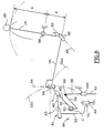
- a bar control device 10 produced according to the invention, represented in a "neutral" position of a box of 12.
- a vertical direction is substantially defined as perpendicular to the ground on which rests a vehicle comprising such a device 10
- a longitudinal direction corresponds substantially to the direction general horizontal of the vehicle
- a transverse direction corresponds to a horizontal transverse direction of the vehicle.
- the bar control device 10 comprises a control lever 16 of substantially vertical orientation and which has at its upper end 18 a knob 20 of grip and maneuver that a driver can operate in both transverse and longitudinal directions, corresponding respectively to the selection and passage of reports of the gearbox 12, of which a casing 14.
- the control lever 16 is articulated relative to a fixed part of the vehicle (not shown) via a plate 17 fixed to the vehicle.
- control lever 16 is connected to a first end 24 of a bar control 26, substantially longitudinal, including a second end 28 is connected to a first end 30 of a bar reduction gear 32, substantially transverse.
- a second end 34 of the reduction bar 32 is connected to a connecting rod 36, substantially transverse, and which is integral in rotation and in axial translation with a shaft 38 of the gearbox 12, substantially vertical, making it possible to order the selection and the passage of the reports of the box of speeds 12 according to a following translational movement the axis A1 of the control shaft 38 and a movement of rotation around this axis.
- the reduction bar 32 is also supported in an intermediate part 33 on a reaction mechanism 40, the details of which will be described with reference to FIG. 2.
- Figure 2 illustrates more precisely the location of elements of the control device 10 in the vicinity of the shaft 38 located on the gearbox housing 14. Details of articulations of the various elements of the device 10 will described in relation to Figures 3 and 4.
- the reduction bar 32 is, in its part intermediate 33, linked to the reaction mechanism 40 by through a first end 44 of a rod reaction 42, the second end of which 46 (not visible in the figure 2) is connected to a first upper end 48 of a reaction link 50 including a second lower end 52 is articulated on the casing 14 around a parallel axis A2 and not coinciding with the axis of the control shaft 38.
- the reaction rod 42 extends in a substantially longitudinal direction A3, is inclined at an angle ⁇ relative to the horizontal, and the connecting rod 50, is substantially bent so that the axis A2 of the connection of the reaction link 50 to the casing 14 of the box is not concurrent with the axis of the link of the reaction link 50 to reaction rod 42.
- the center C of the ball joint of the connection of the reduction bar 32 to the connecting rod 36 is not not concurrent with the axis A1 of the control shaft 38, these conditions being necessary for the control device 10 to move its various elements without blocking and transmission of couples, the elements playing a role of leverage.
- this arrangement is particularly compact and allows the installation of the control device 10 in a limited space on the casing 14 of the box 12 speeds of the vehicle.
- the control device 10 is by elsewhere particularly simple to carry out since its components can be made by simple manufacturing such as forging, molding, or stamping.
- FIG. 3 illustrates more precisely the shapes and connections of the elements of the control device 10 to the vicinity of the control shaft 38 of the gearbox 12. However, reference may also be made to FIG. 2 for the understanding of the forms of the elements involved in links considered.
- the end 28 of the control bar 26 is connected to the first end 30 of the reduction bar 32 by a pivot 54 of axis A4.
- the bar of control 26 has a yoke whose two ears horizontal and parallel 56 are pierced with two holes aligned with the same diameter 55.
- the holes 55 are crossed by a screw 57 which passes through a washer 59 and a first sleeve cylindrical 31 fixed to the first end 30 of the bar reduction 32.
- the first sleeve 31 has a centering ring 35 which receives the screw 57 and two washers in elastomeric material 60 interposed between faces upper and lower of the first sleeve 31 and the ears 56 to dampen vibrations within the device 10.
- a nut 58 receives the screw 57 and allows the tightening of all.
- the end 30 is thus articulated between the two ears 56.
- the reduction bar 32 has a male spherical bearing 62 nested in a female head 64, which is embedded at the end 37 of the connecting rod 36, thus making a ball joint 63 of center C.
- the connecting rod 36 is embedded on a second vertical cylindrical sleeve 66 with an inner diameter 67 is equal to that of the control shaft 38.
- a pin diametral 68 passes through the second sleeve 66 and the axis 38, to allow axial and rotational immobilization of the connecting rod 36 relative to the control shaft 38 by a link 69.
- the link of the reduction bar 32 to reaction mechanism 40 is a sliding pivot link 71 of axis A5 produced by means of a socket 70 in low friction material.
- the end 44 of the reaction rod 42 has a third sleeve 43, one of which inner bore carries the sleeve 70 which slides on the part intermediate 33 of the control bar 32.
- the reaction rod 42 is articulated along its axis A3 to the reaction link 50 by a device which will be described in reference to figure 4.
- the reaction link 50 is linked to the casing 14 at level of its lower end 52 by a fourth sleeve 51, articulated around a pin 74 rigidly linked to the casing 14.
- the pivot connection 75 of axis A2 thus produced comprises pawn 74, the upper end of which has a bearing male spherical 73 received by a female spherical bearing 72 of the sleeve 51 which has the function of immobilizing the rod 50 in its axial displacements of axis A2.
- Pawn 74 has also a cylindrical seat 76 which is received in a ring made of material with low coefficient of friction 78 mounted in a bore 80 of the fourth sleeve 51.
- FIG. 4 illustrates a pivot link 81, of axis A3, of the reaction rod 42 to reaction rod 50.
- the reaction rod 50 is linked to the reaction rod 42 at its upper end 48 by a fifth sleeve 82, articulated on the reaction rod 42.
- the rod 42 has at its second end 46 a male spherical bearing 83 received by a female spherical bearing 84 of the fifth sleeve 82, which has the function of immobilizing the rod 42 in its axial displacements of axis A3.
- Reaction rod 42 also has a cylindrical seat 85 which is received by a ring made of material with low coefficient of friction 86 mounted clamped in a bore 87 of the fifth sleeve 82.
- FIG. 5 illustrates the geometry of the device 10 and more precisely the relative positions different axes of articulation of said device 10.
- the connecting rod 36 is substantially transversely aligned with the reduction bar 32 which is linked to it via the ball joint connection 63.
- the axis A4 of the pivot link 54 linking the bar command 26 at the gear bar 32 is offset relative to the axis A1 of the control shaft 38 for allow the transmission of a couple, in the direction longitudinal gear selection, at the helm reduction 32, indirectly articulated around the link pivot 75 of the reaction mechanism 40.
- the ball joint connection 63 connecting the bar reduction 32 to the connecting rod 36 also being offset by compared to the control shaft 38, it is likely to transmitting said torque to the control shaft 38.
- the axis A2 of the pivot link 75 linking the connecting rod reaction 50 to the casing 14 being neither concurrent with the axis A3 of the pivot link 81, nor coaxial with the control shaft 38, the reaction mechanism 40 is likely to pivot around the pivot link 75 when the control bar 26 is operated longitudinally in the direction of passage of reports to allow rotation of the bar reduction 32, and when the control bar 26 is operated in the direction of selecting reports for allow sliding of the sliding pivot link 71 along of the axis A5 of the reduction bar 32.
- the reaction mechanism 14 therefore allows the bar to reduction 32 to pivot around a vertical virtual axis in the direction of shifting and longitudinal horizontal in the direction of the gear selection. These two virtual axes are not fixed and move with the mechanism.
- the fulcrum of the reaction mechanism 40 on the reduction bar 32 must be able to travel the entire length of the reduction bar 32.
- the axes of rotation previously described moving, the pivot link sliding 71 describes a movement that results from rotation and of a translation. This condition is made possible by the displacement along the reduction bar 32 of the end 44 of the sleeve 43 linked to the reaction rod 42, this second able to rotate along two axes of rotation A2 and A3 materialized by pivot links 75 and 81.
- control bar 26 includes a adjustment device 88 which includes a jumper 90 which comes tighten with a screw 92 which crosses the jumper 90 a hollow part 93 axially split from the control rod 26 which receives a solid portion 94 from said control bar 26 to allow its elongation.
- the setting 88 allows, in the neutral position, to maintain the alignment between the reduction bar 32 and the connecting rod 36, so that two equal and opposite movements of the control bar 36 in the longitudinal direction translate by two angularly equal rotational movements and opposite of the control shaft 38.
- control lever 16 is articulated with respect to a fixed part of the vehicle by a ball joint 96 which determines a ratio of reduction between the movement of the knob 20, and the lower end 22 of the lever 16. This ratio is determined by the ratio of the length A between the part upper 18 and the ball 96 to the length B between the ball 96 and the lower end 22. So whatever the direction of movement of lever 16, the end stroke lower 22 is proportional to the end stroke upper 18.
- the connection of the lower end 22 of the lever 16 at the control bar 26 is produced by a pivot 98 with a substantially transverse axis A6 which makes it possible to articulate the control bar 26 rotating relative to the lever command 16 in the direction of shifting, and make a mounting connection between the bar control 26 and lever 16 in the direction of selection of reports.
- connection pivot 54 of substantially vertical axis A4 makes it possible to articulate the command bar 26 relative to the bar reduction in the direction of shifting, and embedding in the direction of the selection of reports.
- the end 30 of the reduction bar 32 therefore describes a movement in a horizontal plane in the sense of shifting and movement in a vertical transverse plane in the direction of selection reports.
- the reduction bar 32 is linked to the connecting rod 36 by the ball joint 63 of center C.
- the ball joint 63 makes the connecting rod 36 integral with the bar reduction according to any translational movement.
- the connecting rod 36 is linked to the control shaft 38 by the link embedding 69 so that the connecting rod 36 is integral with the rotational and translational movements of the shaft command 38 along a sliding pivot link 100, of axis A1, of connection with the gearbox casing 14.
- the link of the reduction bar 32 to reaction mechanism 40 is realized by the pivot link sliding 71 of axis A5.
- the reaction rod 42 belonging to the reaction mechanism 40 is included in a plane substantially longitudinal and is inclined at an angle ⁇ by relative to a substantially horizontal plane for transmitting selectively the support forces of the bar reduction 32, as will be seen later.
- the reaction rod 42 is linked along its axis A3 by the pivot link 81 to the reaction link 50 which, at its other end, is linked to the box casing 14 by the pivot link 75 of axis A2.
- the movement of the center theoretical of the pivot link 54 corresponding to the intersection axes A4 and A5 is defined by its belonging to the bar 26 and the gear bar 32, so that it describes, with respect to the connecting rod 36, two circles centered on the center C of the ball joint 63 connection, one CE1 being located in a substantially horizontal plane and the other CE2 in a plane substantially vertical.
- the center C of the ball joint 63 being itself located on a circle centered on the axis A2 of the connection pivot 75, the movement of the theoretical center of the pivot link 54 therefore results from the composition of these two movements and is defined by the support of the reaction mechanism 40 on the bar reduction ratio 32.
- the rod 42 is immobilized in the pivot link 81 by compared to the reaction link 50 since the movement of the reduction bar 32 is located in the plane substantially horizontal and opposes rotation of the link pivot 81.
- the movement of the reduction bar 32 therefore causes the drive of the reaction rod 42 and the reaction rod 50 so that the rod 50 rotating around pivot 75, the sliding pivot connection causes the sliding of the reaction rod 42 perpendicular to the reduction bar 32 to support the movement of rotation of the reaction mechanism 40 about the axis A2 of the pivot link 75.
- the horizontal axis rotation of the bar 32 around the center C of the ball joint connection 63 drives the reaction rod 50 via the pivot link sliding 71 which causes the bar 42 to rotate in the connection pivot 81 connected to the reaction link 50, so that the reduction bar movement 32 in the plane substantially vertical causes the training by pressing the level of the sliding pivot connection 71 of the connecting rod 36 according to a substantially vertical direction.
- the connecting rod 36 drives in the same direction the control shaft 38.
- the sliding pivot 71 rotates the reaction mechanism 40 in rotation around the pivot 75.
- the mechanism 40 "steals" under the forces transmitted in the sliding pivot link 71.
- Figure 7 shows the direct benefits of structure previously described with reference to FIG. 6.
- the inclination of the reaction rod 42 at an angle ⁇ relative to horizontally and its pivot link 81 relative to the connecting rod 50 implies that, in the sense of selecting the reports, the pivot link 81 does not transmit to the connecting rod reaction 50 the forces that the sliding pivot link 71 transmits from the reduction bar 32 to the reaction rod 42.
- the reaction mechanism 40 only performs guidance to allow movement of the bar reduction 32 in the vertical plane. In this way, the reduction ratio between the movement of a point in the pivot link 54 and a point on the control shaft 38 is function of dimensions C, D and E which can be seen in Figure 7.
- the pivot link sliding 71 is capable of transmitting reaction forces from the gear bar to the mechanism reaction 40 because the pivot link 81 also transmits the forces from the reaction rod 42 to the reaction link, and the ratio reduction gear in the direction of shifting is function of dimensions E, F, G illustrated in Figure 7.
- Figure 8 provides a comparison by compared to the prior art of document EP-A1-0,072,464 in which a control bar 102 is likely to move in translation substantially along its axis and in rotation substantially around its axis to cause a reduction bar 104, linked in rotation by a link pivot 106 to the control rod 102 and to the casing 14 by a ball 108.
- a reaction lever 110 is linked by a link sliding ball 112 to the gear bar 104 of a part, and by an embedding connection 114 to a shaft of command 116 similar to that 38 previously described, linked to the casing 14 by a sliding pivot link 118 on the other hand.
- the reduction bar takes support on the casing 14 via the ball joint 108 and the support point is single and fixed. It follows that, as can be seen in figure 9, the ratio of reduction in the direction of the selection of the reports and the gear ratio in the direction of the passage of ratios are equal and determined by the dimensions C ', D' and E ' visible in Figure 9.
- the position of the center of the pivot link 106 must be fixedly defined.
- the architecture of the device 10 operating following a single gear ratio, causes on the speed grid an angular shift ⁇ of the trajectory of the lever knob 16 relative to the transverse direction, illustrated in figure 11.
- the device described previously illustrated in Figures 1 to 7 is thus particularly advantageous in that the ratios reduction in the direction of the gear shift and in the direction of selecting reports being completely independent, a positioning defect in the center of the pivot link 106 in the direction of passage does not cause defective trajectory of the lever knob 16 in the direction of selection, and a positioning fault of the pivot link 128 in the direction of selection does not cause a defect of trajectory of the knob of the lever 16 in the direction of passage.
Landscapes
- Engineering & Computer Science (AREA)
- General Engineering & Computer Science (AREA)
- Mechanical Engineering (AREA)
- Arrangement Or Mounting Of Control Devices For Change-Speed Gearing (AREA)
- Gear-Shifting Mechanisms (AREA)
Applications Claiming Priority (2)
| Application Number | Priority Date | Filing Date | Title |
|---|---|---|---|
| FR9803113A FR2775940B1 (fr) | 1998-03-13 | 1998-03-13 | Commande par barres de boite de vitesses |
| FR9803113 | 1998-03-13 |
Publications (1)
| Publication Number | Publication Date |
|---|---|
| EP0942201A1 true EP0942201A1 (de) | 1999-09-15 |
Family
ID=9524023
Family Applications (1)
| Application Number | Title | Priority Date | Filing Date |
|---|---|---|---|
| EP99400614A Withdrawn EP0942201A1 (de) | 1998-03-13 | 1999-03-12 | Getriebeschaltanordnung mit Stangen |
Country Status (2)
| Country | Link |
|---|---|
| EP (1) | EP0942201A1 (de) |
| FR (1) | FR2775940B1 (de) |
Citations (4)
| Publication number | Priority date | Publication date | Assignee | Title |
|---|---|---|---|---|
| FR2445240A1 (fr) * | 1978-12-29 | 1980-07-25 | Nissan Motor | Dispositif de commande de transmission pour vehicules automobiles |
| GB2050538A (en) * | 1979-05-31 | 1981-01-07 | Audi Ag | Shift apparatus for the mechanical remote control of the gear box of a motor vehicle |
| EP0072464A1 (de) | 1981-08-14 | 1983-02-23 | Regie Nationale Des Usines Renault | Handsteuervorrichtung für die Gänge eines Wechselgetriebes |
| US4653341A (en) * | 1984-06-20 | 1987-03-31 | Alfa Romeo Auto S.P.A. | Device for manually controlling a motor vehicle change-speed gear unit |
-
1998
- 1998-03-13 FR FR9803113A patent/FR2775940B1/fr not_active Expired - Fee Related
-
1999
- 1999-03-12 EP EP99400614A patent/EP0942201A1/de not_active Withdrawn
Patent Citations (4)
| Publication number | Priority date | Publication date | Assignee | Title |
|---|---|---|---|---|
| FR2445240A1 (fr) * | 1978-12-29 | 1980-07-25 | Nissan Motor | Dispositif de commande de transmission pour vehicules automobiles |
| GB2050538A (en) * | 1979-05-31 | 1981-01-07 | Audi Ag | Shift apparatus for the mechanical remote control of the gear box of a motor vehicle |
| EP0072464A1 (de) | 1981-08-14 | 1983-02-23 | Regie Nationale Des Usines Renault | Handsteuervorrichtung für die Gänge eines Wechselgetriebes |
| US4653341A (en) * | 1984-06-20 | 1987-03-31 | Alfa Romeo Auto S.P.A. | Device for manually controlling a motor vehicle change-speed gear unit |
Also Published As
| Publication number | Publication date |
|---|---|
| FR2775940B1 (fr) | 2000-07-07 |
| FR2775940A1 (fr) | 1999-09-17 |
Similar Documents
| Publication | Publication Date | Title |
|---|---|---|
| FR2511329A1 (fr) | Systeme de direction permettant de braquer les roues avant et les roues arriere d'un vehicule | |
| EP0072464B1 (de) | Handsteuervorrichtung für die Gänge eines Wechselgetriebes | |
| FR2764358A1 (fr) | Dispositif pour actionner un arbre de commutation d'une boite de vitesses | |
| EP0565400B1 (de) | Steuervorrichtung für das Geschwindigkeitswechselgetriebe eines Kraftfahrzeuges | |
| EP0444994A1 (de) | Verstellbare Lenksäule | |
| EP0560645B1 (de) | Gangschalthebelvorrichtung, insbesondere für Kraftfahrzeuge | |
| EP1538067B1 (de) | Kraftfahrzeugachse und Stellglied für solche Achse | |
| EP0942201A1 (de) | Getriebeschaltanordnung mit Stangen | |
| EP0115224B1 (de) | Steuervorrichtung für Gangschaltgetriebe mit Stange auf gleitendem Kugelkopf | |
| FR2566342A1 (fr) | Dispositif pour la commande manuelle de la boite de vitesses d'un vehicule automobile | |
| EP0864780B1 (de) | Vorrichtung zum Schalten eines Gangwechselgetriebes eines Kraftfahrzeuges | |
| EP0296909A1 (de) | Vorrichtung zur vibrationslosen Übertragung von Bewegungen einer elektrischen Betätigung auf die Trägerplatte eines Rückspiegels | |
| FR2638547A1 (fr) | Appareil de commande de distributeurs | |
| EP1642048B1 (de) | Externe getriebesteuervorrichtung für ein armaturenbrett | |
| EP0084472B1 (de) | Verstelleinrichtung für Schaltgetriebe | |
| EP1329292A1 (de) | Spannvorrichtung, insbesondere für Fahrzeugkarosserieteile | |
| EP0577900A1 (de) | Vorrichtung zum automatischen Betätigen eines Getriebeschalthebels | |
| FR2711951A1 (fr) | Dispositif de pivotement d'un dossier vis-à-vis de la place assise du siège d'un véhicule automobile. | |
| FR2856961A1 (fr) | Dispositif de commande externe de boite de vitesses pour planche de bord de vehicule | |
| FR2807977A1 (fr) | Systeme d'actionnement d'une timonerie de commande d'un equipage mobile dans un dispositif d'accouplement pilote, tel qu'un embrayage par exemple | |
| FR2952015A1 (fr) | Vehicule comportant un dispositif de reglage en hauteur d'une colonne de direction | |
| FR2721575A1 (fr) | Direction à crémaillère à denture hélicoïdale assistée par servomoteur. | |
| FR2849809A1 (fr) | Dispositif de commande deportee d'une boite de vitesses | |
| FR2824039A1 (fr) | Ensemble de direction a colonne de direction reglable en position et vehicule automobile correspondant | |
| FR2678193A1 (fr) | Robot de soudage par faisceau laser. |
Legal Events
| Date | Code | Title | Description |
|---|---|---|---|
| PUAI | Public reference made under article 153(3) epc to a published international application that has entered the european phase |
Free format text: ORIGINAL CODE: 0009012 |
|
| AK | Designated contracting states |
Kind code of ref document: A1 Designated state(s): AT BE CH CY DE DK ES FI FR GB GR IE IT LI LU MC NL PT SE |
|
| AX | Request for extension of the european patent |
Free format text: AL;LT;LV;MK;RO;SI |
|
| STAA | Information on the status of an ep patent application or granted ep patent |
Free format text: STATUS: THE APPLICATION HAS BEEN WITHDRAWN |
|
| 18W | Application withdrawn |
Withdrawal date: 20000329 |