EP0942208A2 - Dichtungsbausatz - Google Patents
Dichtungsbausatz Download PDFInfo
- Publication number
- EP0942208A2 EP0942208A2 EP99102002A EP99102002A EP0942208A2 EP 0942208 A2 EP0942208 A2 EP 0942208A2 EP 99102002 A EP99102002 A EP 99102002A EP 99102002 A EP99102002 A EP 99102002A EP 0942208 A2 EP0942208 A2 EP 0942208A2
- Authority
- EP
- European Patent Office
- Prior art keywords
- sleeve
- lip
- disc
- sealing
- kit according
- Prior art date
- Legal status (The legal status is an assumption and is not a legal conclusion. Google has not performed a legal analysis and makes no representation as to the accuracy of the status listed.)
- Granted
Links
- 238000007789 sealing Methods 0.000 title claims abstract description 36
- 238000000034 method Methods 0.000 claims abstract description 6
- 239000004033 plastic Substances 0.000 claims abstract description 5
- 239000000463 material Substances 0.000 claims abstract description 4
- 230000001681 protective effect Effects 0.000 claims 1
- 239000002861 polymer material Substances 0.000 abstract description 3
- 239000004810 polytetrafluoroethylene Substances 0.000 description 4
- 229920001343 polytetrafluoroethylene Polymers 0.000 description 4
- 238000004519 manufacturing process Methods 0.000 description 3
- 239000002184 metal Substances 0.000 description 3
- 241000209035 Ilex Species 0.000 description 2
- 238000006073 displacement reaction Methods 0.000 description 2
- 239000000428 dust Substances 0.000 description 2
- 238000002485 combustion reaction Methods 0.000 description 1
- 230000003247 decreasing effect Effects 0.000 description 1
- 238000004049 embossing Methods 0.000 description 1
- 230000004927 fusion Effects 0.000 description 1
- 239000007788 liquid Substances 0.000 description 1
- 230000003446 memory effect Effects 0.000 description 1
- 230000002028 premature Effects 0.000 description 1
- 230000002787 reinforcement Effects 0.000 description 1
- 238000003860 storage Methods 0.000 description 1
Images

Classifications
-
- F—MECHANICAL ENGINEERING; LIGHTING; HEATING; WEAPONS; BLASTING
- F16—ENGINEERING ELEMENTS AND UNITS; GENERAL MEASURES FOR PRODUCING AND MAINTAINING EFFECTIVE FUNCTIONING OF MACHINES OR INSTALLATIONS; THERMAL INSULATION IN GENERAL
- F16J—PISTONS; CYLINDERS; SEALINGS
- F16J15/00—Sealings
- F16J15/16—Sealings between relatively-moving surfaces
- F16J15/32—Sealings between relatively-moving surfaces with elastic sealings, e.g. O-rings
- F16J15/3204—Sealings between relatively-moving surfaces with elastic sealings, e.g. O-rings with at least one lip
- F16J15/3228—Sealings between relatively-moving surfaces with elastic sealings, e.g. O-rings with at least one lip formed by deforming a flat ring
-
- F—MECHANICAL ENGINEERING; LIGHTING; HEATING; WEAPONS; BLASTING
- F16—ENGINEERING ELEMENTS AND UNITS; GENERAL MEASURES FOR PRODUCING AND MAINTAINING EFFECTIVE FUNCTIONING OF MACHINES OR INSTALLATIONS; THERMAL INSULATION IN GENERAL
- F16J—PISTONS; CYLINDERS; SEALINGS
- F16J15/00—Sealings
- F16J15/16—Sealings between relatively-moving surfaces
- F16J15/32—Sealings between relatively-moving surfaces with elastic sealings, e.g. O-rings
- F16J15/3268—Mounting of sealing rings
Definitions
- the invention relates to a seal kit.
- a seal kit is already known in which the PTFE existing sealing lip of a sealing ring during storage and Transport through a cylindrical sleeve inserted into the inner circumference is supported to prevent the sealing lip from deforming back and your production-related level while reducing the inside diameter Takes shape again before assembly, because this creates problems with the Assembly can result. The tendency to such extreme deformation is based on the so-called memory effect, especially of PTFE materials is own. Before the actual assembly, the well-known Sealing rings removed from the sleeve and installed independently of it.
- the sealing lip which is made of polymer material, usually has to be over a more or less sharp-edged end of the to be sealed Shaft or rod are pushed away, which often results in a Damage to the sealing lip leads to premature failure of the sealing ring.
- the liability question is usually difficult in such cases to enlighten.
- the invention has for its object a kit of the beginning to show mentioned type, which makes it possible to use a sealing ring with a sealing lip made of polymer material while avoiding uncontrollable Mount damage to the sealing lip on one shaft end.
- the invention takes advantage of the fact that the hollow conical primary and Secondary sealing lip of the sealing ring at least during the intended Use axially to project in the opposite direction to what it is excludes that such a sealing ring after a previous one Remove from the sleeve in the rearward direction via its front end can be guided away and placed again on the sleeve.
- the sealing ring starting from the sleeve directly onto the shaft or rod postponed and placed in the gap to be sealed. The must End of the shaft or rod inserted into the recess of the sleeve what it excludes the sealing lip from objects other than the surfaces touches the sleeve and the shaft or rod. An unpredictable one Damage is completely excluded. After assembly of the sealing ring can the sleeve with the permanently attached disc removed and returned to the seal manufacturer if necessary.
- the sleeve has one at the second end has reduced outer diameter in which at least one secondary lip the area of the inner diameter is included. If there are several secondary lips are provided, there is the possibility of deviating them to train and shape one another and, for example, to an external one Secondary lip made of felt in the direction of the space to be sealed Secondary rubber lip to follow while the primary lip is made PTFE or rubber. Especially with regard to the sealing of the Crankshafts of internal combustion engines have become such Training excellently proven.
- the sleeve and / or disc can be made of plastic. With regard to the large mechanical loads that occur during automatic assembly result, it has proven to be advantageous if the sleeve by a Deep drawing process is produced from sheet metal.
- the disc and the sleeve can merge into one another in one piece be formed, for example in an embodiment made of plastic consists.
- the disc is separate generated and connected to the sleeve after attaching the sealing ring is.
- the disc can be made of plastic and, for example be connected to the sleeve by fusion bonding.
- the disc and the sleeve through a riveted connection to fix each other.
- Other methods and options for manufacturing an inseparable connection between the disc and the sleeve are the Expert familiar. Their application is important to the sealing lips in front of them Transfer to the shaft or rod to be sealed for secondary actions and in particular to make damage inaccessible.
- the sealing kit shown in Figures 1 and 2 comprises a sealing ring Conventional design, for example when using a crankshaft Application can come.
- the sealing ring consists of a reinforcement ring made of sheet metal, which is vulcanized into a rubber ring and in the radial direction protruding inside a dust lip 11, which consists of felt, a Secondary lip 14, which is made of rubber and a primary lip 2, which is made of PTFE exists, the latter due to the manufacture of an annular shape and in the area of the inner circumference in the direction of the space to be sealed is bulging like a trumpet.
- To the primary lip created in this way Giving sufficient flexibility in the area of the inner circumference is the it forming disc in the area of the opposite one another Surfaces with spiral grooves that gap each other assigned.
- the grooves can be cut through, however optionally also by an embossing process at elevated temperature be generated. They increase the flexibility of the primary lip a return flow of leakage liquid passing through the sealing gap into the space to be sealed.
- the sleeve 3 consists of sheet metal and is produced by a deep-drawing process. you first end 5 has an angularly open recess 4 provided in the area of the end on the outer circumference of the to be sealed Shaft or rod 6 can be put on. The first end is free of sharp ones Edges that could damage the sealing lip.
- the second end 7 has a rounded inward decreasing Outside diameter, which is dimensioned so that the felt circularly shaped dust lip 11 with an inner diameter that is smaller than the outside diameter of the shaft to be sealed, below Avoiding deformation can be included.
- the inner diameter of the secondary lip 14 is smaller than that Outside diameter of the shaft or rod to be sealed 6.
- the Secondary lip is hollow conical. It has, based on the Primary lip, an opposite direction of inclination.
- the sleeve 3 In the axial direction, the sleeve 3 is inseparable from its second end an annular, essentially flat disk 8 connected, the disc 8 and the sleeve 3 in this area have radially inward facing collar 12 which the end face of the sealing shaft or rod 6 partially overlaps.
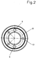
- the federal government 12 of the Disc 8 and sleeve 3 are at two opposite points of Holes 9 penetrated through which the kit during assembly immovable with the end of the shaft or rod to be sealed 6 can be screwed. It is then possible to seal 1 over the first end 5 of the sleeve 3 directly onto the outer circumference the shaft or rod 6 to be sealed and in the to place the gap to be sealed without the risk of occurrence of Canting occurs. Subsequently, the one with the disk 8 Removed inseparable unit-forming sleeve 3 and optionally to the Seal manufacturers are returned.
- the disk 8 is at three locations 10 distributed in the circumferential direction columnar projections provided in corresponding holes of the Collar 12 of the sleeve 3 insertable and on the face 13 facing Side of the federal government 12 are mushroom-like fused.
- a violent one Removal of the disc 8 from the sleeve 3 leads to the breaking off Projections, which signals the seal manufacturer that the Seal kit has been used improperly. For the Clarifying the question of liability in the event of complaints can be a great advantage be.
Landscapes
- Engineering & Computer Science (AREA)
- General Engineering & Computer Science (AREA)
- Mechanical Engineering (AREA)
- Sealing With Elastic Sealing Lips (AREA)
- Breeding Of Plants And Reproduction By Means Of Culturing (AREA)
- Apparatus Associated With Microorganisms And Enzymes (AREA)
- Prostheses (AREA)
- Gasket Seals (AREA)
Abstract
Description
- Figur 1:
- einen beispielhaften Dichtungsbausatz in halbgeschnittener Darstellung,
- Figur 2:
- den in Figur 1 gezeigten Bausatz in einer Ansicht von vorn.
Claims (7)
- Dichtungsbausatz, umfassend:a) einen Dichtring, der innenseitig durch zumindest eine zumindest in einem Teilbereich hohlkegelige Primärlippe und Sekundärlippe aus polymerem Werkstoff begrenzt ist, die zumindest während der bestimmungsgemäßen Verwendung eine entgegengesetzte Neigungsrichtung haben,b) eine zumindest in die Primärlippe (2) eingeführte Hülse (3) mit einer winkelförmig nach innen offenen Ausnehmung (4) an den ersten Ende (5), die mit der Ausnehmung (4) auf den Außenumfang einer Welle oder Stange (6) aufstülpbar ist,c) eine an dem zweiten Ende (7) der Hülse (3) unlösbar festgelegte Scheibe (8), die die Primärlippe (2) zumindest teilweise in radialer Richtung übergreift.
- Dichtungsbausatz nach Anspruch 1, dadurch gekennzeichnet, daß die Hülse (3) an dem zweiten Ende (7) einen reduzierten Außendurchmesser hat, in den eine Schutzlippe (11) einfügbar ist.
- Dichtungsbausatz nach Anspruch 1 oder 2, dadurch gekennzeichnet, daß die Hülse (3) durch einen Tiefziehprozeß erzeugt ist.
- Dichtungsbausatz nach einem der Ansprüche 1 bis 3, dadurch gekennzeichnet, daß die Scheibe (8) und die Hülse (3) einstückig ineinander übergehend ausgebildet sind.
- Dichtungsbausatz nach einem der Ansprüche 1 bis 3, dadurch gekennzeichnet, daß die Scheibe (8) separat erzeugt und nach dem Auffügen des Dichtrings (1) auf die Hülse (3) mit dieser verbunden ist.
- Dichtungsbausatz nach einem der Ansprüche 1 bis 5, dadurch gekennzeichnet, daß die Scheibe (8) und/oder die Hülse (3) an dem zweiten Ende (7) einen radial nach innen weisenden Bund (12) aufweist, der die Stirnfläche der Welle oder Stange (6) zumindest teilweise übergreift.
- Dichtungsbausatz nach einem der Ansprüche 1 bis 6, dadurch gekennzeichnet, daß zumindest die Scheibe (8) aus Kunststoff besteht.
Applications Claiming Priority (2)
| Application Number | Priority Date | Filing Date | Title |
|---|---|---|---|
| DE19810113 | 1998-03-09 | ||
| DE19810113A DE19810113C2 (de) | 1998-03-09 | 1998-03-09 | Dichtungsbausatz |
Publications (3)
| Publication Number | Publication Date |
|---|---|
| EP0942208A2 true EP0942208A2 (de) | 1999-09-15 |
| EP0942208A3 EP0942208A3 (de) | 2000-05-31 |
| EP0942208B1 EP0942208B1 (de) | 2004-10-20 |
Family
ID=7860253
Family Applications (1)
| Application Number | Title | Priority Date | Filing Date |
|---|---|---|---|
| EP99102002A Expired - Lifetime EP0942208B1 (de) | 1998-03-09 | 1999-02-01 | Dichtungsbausatz |
Country Status (3)
| Country | Link |
|---|---|
| EP (1) | EP0942208B1 (de) |
| DE (1) | DE19810113C2 (de) |
| ES (1) | ES2230751T3 (de) |
Cited By (5)
| Publication number | Priority date | Publication date | Assignee | Title |
|---|---|---|---|---|
| FR2844327A1 (fr) * | 2002-09-06 | 2004-03-12 | Peugeot Citroen Automobiles Sa | Joint d'etancheite et dispositif de transmission de couple comportant un tel joint. |
| EP1359353A3 (de) * | 2002-05-03 | 2004-03-24 | Carl Freudenberg KG | Dichtungsanordnung mit einem Montage- und / oder Transportring |
| DE10325254B4 (de) * | 2003-06-03 | 2007-02-15 | Carl Freudenberg Kg | Montageschutzring |
| DE102012009068B4 (de) * | 2012-05-09 | 2016-10-13 | Carl Freudenberg Kg | Montageträger für eine Dichtung und Verfahren zum Montieren einer Dichtung |
| WO2022063631A1 (de) * | 2020-09-28 | 2022-03-31 | Magna powertrain gmbh & co kg | Montagewerkzeug zur positionierung eines wellendichtrings auf einer welle sowie verfahren zur herstellung einer wellenabdichtung |
Families Citing this family (3)
| Publication number | Priority date | Publication date | Assignee | Title |
|---|---|---|---|---|
| RU2162170C1 (ru) * | 2000-01-06 | 2001-01-20 | Закрытое акционерное общество "Тольяттинский завод автоагрегатов" | Втулка комбинированная |
| DE102004008820B4 (de) * | 2004-02-20 | 2015-09-24 | Carl Freudenberg Kg | Schutzring |
| DE102013114534B4 (de) * | 2013-12-19 | 2023-05-17 | Thyssenkrupp Presta Teccenter Ag | Anordnung eines Aufnahmeelementes zur Aufnahme eines Wellendichtringes |
Family Cites Families (6)
| Publication number | Priority date | Publication date | Assignee | Title |
|---|---|---|---|---|
| DE2340275C2 (de) * | 1973-08-09 | 1975-06-12 | Ford-Werke Ag, 5000 Koeln | Transportschutz- und Montagering für Wellendichtringe |
| GB2133840B (en) * | 1983-01-18 | 1986-07-02 | Fenner Co Ltd J H | Transportation and fitting ring for a radial lip seal and a material for use in relation thereto |
| GB2199381A (en) * | 1986-12-23 | 1988-07-06 | Ford Motor Co | Seal installation |
| DE3838760A1 (de) * | 1988-11-16 | 1990-05-17 | Kaco Gmbh Co | Dichtring |
| DE4141320C1 (en) * | 1991-12-14 | 1993-06-09 | Goetze Ag, 5093 Burscheid, De | Transport and assembly sleeve for shaft-sealing rings - has axial stop on tapered rearward part to prevent ring from slipping during transfer to shaft |
| DE4224995C1 (de) * | 1992-07-29 | 1993-12-16 | Goetze Ag | Transport- und Montagehülse |
-
1998
- 1998-03-09 DE DE19810113A patent/DE19810113C2/de not_active Expired - Lifetime
-
1999
- 1999-02-01 ES ES99102002T patent/ES2230751T3/es not_active Expired - Lifetime
- 1999-02-01 EP EP99102002A patent/EP0942208B1/de not_active Expired - Lifetime
Non-Patent Citations (1)
| Title |
|---|
| None |
Cited By (13)
| Publication number | Priority date | Publication date | Assignee | Title |
|---|---|---|---|---|
| CN100337052C (zh) * | 2002-05-03 | 2007-09-12 | 卡尔弗罗伊登柏格两合公司 | 带一装配和运输套的密封装置 |
| EP1359353A3 (de) * | 2002-05-03 | 2004-03-24 | Carl Freudenberg KG | Dichtungsanordnung mit einem Montage- und / oder Transportring |
| FR2844327A1 (fr) * | 2002-09-06 | 2004-03-12 | Peugeot Citroen Automobiles Sa | Joint d'etancheite et dispositif de transmission de couple comportant un tel joint. |
| DE10325254C5 (de) * | 2003-06-03 | 2011-03-31 | Carl Freudenberg Kg | Montageschutzring |
| US7284759B2 (en) | 2003-06-03 | 2007-10-23 | Carl Freudenberg Kg | Mounting guard ring |
| US7651102B2 (en) | 2003-06-03 | 2010-01-26 | Carl Freudenberg Kg | Mounting guard ring |
| DE10325254B4 (de) * | 2003-06-03 | 2007-02-15 | Carl Freudenberg Kg | Montageschutzring |
| US8292302B2 (en) | 2003-06-03 | 2012-10-23 | Carl Freudenberg Kg | Mounting guard ring |
| US8474828B2 (en) | 2003-06-03 | 2013-07-02 | Carl Freudenberg Kg | Mounting guard ring |
| US8910948B2 (en) | 2003-06-03 | 2014-12-16 | Carl Freudenberg Kg | Mounting guard ring |
| DE102012009068B4 (de) * | 2012-05-09 | 2016-10-13 | Carl Freudenberg Kg | Montageträger für eine Dichtung und Verfahren zum Montieren einer Dichtung |
| WO2022063631A1 (de) * | 2020-09-28 | 2022-03-31 | Magna powertrain gmbh & co kg | Montagewerkzeug zur positionierung eines wellendichtrings auf einer welle sowie verfahren zur herstellung einer wellenabdichtung |
| US12564923B2 (en) | 2020-09-28 | 2026-03-03 | Magna powertrain gmbh & co kg | Mounting tool for positioning a shaft sealing ring on a shaft and method for producing a shaft seal |
Also Published As
| Publication number | Publication date |
|---|---|
| EP0942208B1 (de) | 2004-10-20 |
| DE19810113A1 (de) | 1999-09-23 |
| DE19810113C2 (de) | 2000-07-27 |
| ES2230751T3 (es) | 2005-05-01 |
| EP0942208A3 (de) | 2000-05-31 |
Similar Documents
| Publication | Publication Date | Title |
|---|---|---|
| DE69121948T2 (de) | Unterleg-Drucklager | |
| DE69000783T2 (de) | Wasserhahn-einlassleitungsverbindung. | |
| DE68902328T2 (de) | Fluessigkeits-kupplungszusammenbauten. | |
| DE3120271C2 (de) | Vorrichtung zum Verbinden eines Geschwindigkeitsmessers mit einer flexiblen Welle | |
| DE2553290A1 (de) | Hydrodynamische wellendichtung, und verfahren zu ihrer herstellung | |
| EP0332759A2 (de) | Vorrichtung zur axialen Befestigung für die Verbindung von Rohrstücken | |
| DE3631812A1 (de) | Rohr- oder schlauchverbindungselement | |
| DE60119049T2 (de) | Pressfitting | |
| EP2063136A2 (de) | Verbindungselement mit einer Schraube und einer daran unverlierbar angeordneten Hülse | |
| DE2830818C2 (de) | Einsetzbarer Bordring für ein Radialwälzlager | |
| DE3536327A1 (de) | Rollenbodenanordnung fuer eine tragrolle | |
| EP0612947A1 (de) | Schubgesicherte Muffenverbindung | |
| DE69814074T2 (de) | Faltenbalgförmige Abdeckung | |
| DE602004000830T2 (de) | Kreuzgelenk mit Axiallager zur Halterung der Lagerbuchse | |
| DE9406691U1 (de) | Vorrichtung zur Verbindung von Lagerringen | |
| DE69109892T2 (de) | Lager. | |
| DE2952468A1 (de) | Steckbare verbindungsvorrichtung mit schnappverschluss | |
| DE69909359T2 (de) | Distanzhülse | |
| EP0942208B1 (de) | Dichtungsbausatz | |
| DE19857033B4 (de) | Axiallager | |
| DE29901935U1 (de) | Leitungssystem | |
| DE2602002A1 (de) | Sicherungs- und/oder distanzring | |
| EP1503096B1 (de) | Halteelement zur Fixierung wenigstens eines Lagers | |
| DE102011107352A1 (de) | Ringfilter für flüssige oder gasförmige Medien | |
| DE3204193C1 (de) | Wellendichtung |
Legal Events
| Date | Code | Title | Description |
|---|---|---|---|
| PUAI | Public reference made under article 153(3) epc to a published international application that has entered the european phase |
Free format text: ORIGINAL CODE: 0009012 |
|
| AK | Designated contracting states |
Kind code of ref document: A2 Designated state(s): ES FR GB |
|
| AX | Request for extension of the european patent |
Free format text: AL;LT;LV;MK;RO;SI |
|
| PUAL | Search report despatched |
Free format text: ORIGINAL CODE: 0009013 |
|
| AK | Designated contracting states |
Kind code of ref document: A3 Designated state(s): AT BE CH CY DE DK ES FI FR GB GR IE IT LI LU MC NL PT SE |
|
| AX | Request for extension of the european patent |
Free format text: AL;LT;LV;MK;RO;SI |
|
| 17P | Request for examination filed |
Effective date: 20000429 |
|
| AKX | Designation fees paid |
Free format text: ES FR GB |
|
| RAP1 | Party data changed (applicant data changed or rights of an application transferred) |
Owner name: CARL FREUDENBERG KG |
|
| REG | Reference to a national code |
Ref country code: DE Ref legal event code: 8566 |
|
| 17Q | First examination report despatched |
Effective date: 20030626 |
|
| GRAP | Despatch of communication of intention to grant a patent |
Free format text: ORIGINAL CODE: EPIDOSNIGR1 |
|
| GRAS | Grant fee paid |
Free format text: ORIGINAL CODE: EPIDOSNIGR3 |
|
| GRAA | (expected) grant |
Free format text: ORIGINAL CODE: 0009210 |
|
| AK | Designated contracting states |
Kind code of ref document: B1 Designated state(s): ES FR GB |
|
| PG25 | Lapsed in a contracting state [announced via postgrant information from national office to epo] |
Ref country code: GB Free format text: LAPSE BECAUSE OF FAILURE TO SUBMIT A TRANSLATION OF THE DESCRIPTION OR TO PAY THE FEE WITHIN THE PRESCRIBED TIME-LIMIT Effective date: 20041020 |
|
| REG | Reference to a national code |
Ref country code: GB Ref legal event code: FG4D Free format text: NOT ENGLISH |
|
| REG | Reference to a national code |
Ref country code: ES Ref legal event code: FG2A Ref document number: 2230751 Country of ref document: ES Kind code of ref document: T3 |
|
| GBV | Gb: ep patent (uk) treated as always having been void in accordance with gb section 77(7)/1977 [no translation filed] |
Effective date: 20041020 |
|
| ET | Fr: translation filed | ||
| PLBE | No opposition filed within time limit |
Free format text: ORIGINAL CODE: 0009261 |
|
| STAA | Information on the status of an ep patent application or granted ep patent |
Free format text: STATUS: NO OPPOSITION FILED WITHIN TIME LIMIT |
|
| 26N | No opposition filed |
Effective date: 20050721 |
|
| PGFP | Annual fee paid to national office [announced via postgrant information from national office to epo] |
Ref country code: ES Payment date: 20060206 Year of fee payment: 8 |
|
| REG | Reference to a national code |
Ref country code: ES Ref legal event code: FD2A Effective date: 20070202 |
|
| PG25 | Lapsed in a contracting state [announced via postgrant information from national office to epo] |
Ref country code: ES Free format text: LAPSE BECAUSE OF NON-PAYMENT OF DUE FEES Effective date: 20070202 |
|
| REG | Reference to a national code |
Ref country code: FR Ref legal event code: PLFP Year of fee payment: 18 |
|
| REG | Reference to a national code |
Ref country code: FR Ref legal event code: PLFP Year of fee payment: 19 |
|
| REG | Reference to a national code |
Ref country code: FR Ref legal event code: PLFP Year of fee payment: 20 |
|
| PGFP | Annual fee paid to national office [announced via postgrant information from national office to epo] |
Ref country code: FR Payment date: 20180227 Year of fee payment: 20 |