EP0942281A2 - Messschaltung zur Ermittlung der Konzentration eines oder mehrerer Gase in einem Gasgemisch - Google Patents
Messschaltung zur Ermittlung der Konzentration eines oder mehrerer Gase in einem Gasgemisch Download PDFInfo
- Publication number
- EP0942281A2 EP0942281A2 EP99103014A EP99103014A EP0942281A2 EP 0942281 A2 EP0942281 A2 EP 0942281A2 EP 99103014 A EP99103014 A EP 99103014A EP 99103014 A EP99103014 A EP 99103014A EP 0942281 A2 EP0942281 A2 EP 0942281A2
- Authority
- EP
- European Patent Office
- Prior art keywords
- gas sensor
- sensor element
- measuring
- stage
- measuring circuit
- Prior art date
- Legal status (The legal status is an assumption and is not a legal conclusion. Google has not performed a legal analysis and makes no representation as to the accuracy of the status listed.)
- Withdrawn
Links
Images



Classifications
-
- G—PHYSICS
- G01—MEASURING; TESTING
- G01N—INVESTIGATING OR ANALYSING MATERIALS BY DETERMINING THEIR CHEMICAL OR PHYSICAL PROPERTIES
- G01N33/00—Investigating or analysing materials by specific methods not covered by groups G01N1/00 - G01N31/00
- G01N33/0004—Gaseous mixtures, e.g. polluted air
- G01N33/0009—General constructional details of gas analysers, e.g. portable test equipment
- G01N33/0027—General constructional details of gas analysers, e.g. portable test equipment concerning the detector
- G01N33/0036—General constructional details of gas analysers, e.g. portable test equipment concerning the detector specially adapted to detect a particular component
- G01N33/0037—NOx
-
- G—PHYSICS
- G01—MEASURING; TESTING
- G01N—INVESTIGATING OR ANALYSING MATERIALS BY DETERMINING THEIR CHEMICAL OR PHYSICAL PROPERTIES
- G01N27/00—Investigating or analysing materials by the use of electric, electrochemical, or magnetic means
- G01N27/02—Investigating or analysing materials by the use of electric, electrochemical, or magnetic means by investigating impedance
- G01N27/04—Investigating or analysing materials by the use of electric, electrochemical, or magnetic means by investigating impedance by investigating resistance
- G01N27/12—Investigating or analysing materials by the use of electric, electrochemical, or magnetic means by investigating impedance by investigating resistance of a solid body in dependence upon absorption of a fluid; of a solid body in dependence upon reaction with a fluid, for detecting components in the fluid
- G01N27/122—Circuits particularly adapted therefor, e.g. linearising circuits
-
- Y—GENERAL TAGGING OF NEW TECHNOLOGICAL DEVELOPMENTS; GENERAL TAGGING OF CROSS-SECTIONAL TECHNOLOGIES SPANNING OVER SEVERAL SECTIONS OF THE IPC; TECHNICAL SUBJECTS COVERED BY FORMER USPC CROSS-REFERENCE ART COLLECTIONS [XRACs] AND DIGESTS
- Y02—TECHNOLOGIES OR APPLICATIONS FOR MITIGATION OR ADAPTATION AGAINST CLIMATE CHANGE
- Y02A—TECHNOLOGIES FOR ADAPTATION TO CLIMATE CHANGE
- Y02A50/00—TECHNOLOGIES FOR ADAPTATION TO CLIMATE CHANGE in human health protection, e.g. against extreme weather
- Y02A50/20—Air quality improvement or preservation, e.g. vehicle emission control or emission reduction by using catalytic converters
Definitions
- the invention relates to a measuring circuit for determining the Concentration of one or more gases in a gas mixture.
- Generic measuring circuits have an oscillating circuit, which comprises a gas sensor element with variable resistance, where the resistance of the gas sensor element and thus the natural frequency of the resonant circuit depending on the concentration of the gas or gases in the gas mixture changed.
- WO 95/29072 discloses a measuring circuit in which a gas sensor element to be heated together with an as Oscillator-connected timer block is used. In this The gas sensor element is wired with a sharp circuit Square wave signal is applied, whereby the timer module is connected is that the frequency of the square wave signal, with which is applied to the gas sensor element, depending changed by its resistance. The frequency of the resulting Rectangular signal can be measured, whereby from this a conclusion about the current resistance of the gas sensor element results. From the current resistance of the gas sensor element can depend on the content of one or more gases of a gas mixture can be closed on the gas sensor element acts.
- measuring circuits are known, the two different Have gas sensor elements, one of which is a gas sensor element is suitable for the detection of oxidizable gases, while the other gas sensor element is reducible for detection Serves gases.
- so-called “Masking effects” are eliminated when using of a single sensor element occur.
- a disadvantage of all known measuring circuits is that only inaccurate measurements of the concentration of one or more Gases in a gas mixture are possible.
- the signal generator the gas sensor elements with a measurement signal charged, its derivation over time essentially runs steadily.
- a signal indicates its derivation essentially constant over time, none or only very slight “kinks” in its course that sharp edges, simple edges or abrupt changes could be.
- "Kinks” are particularly clear peaks of the measurement signal, which are also referred to as "peaks". In the area around such peaks the derivative of the signal has a very large one after the time on one side of the peak positive value while the derivative on the other Side of the peak a very small, especially negative Assumes value. But also cause other kinks in the measurement signal, that the derivation of the measurement signal is discontinuous over time have, since the slope of the Measurement signal changes abruptly.
- This aspect of the invention is based on the knowledge that Semiconductor gas sensor elements very sensitive to abrupt Changes in the slope of the measurement signal react. According to the invention therefore provides that the measurement signal has a shape assumes by simple interventions and / or changes in the measuring circuit is definable. Sinusoidal signals, with in the form of a rectangular signal with rounded edges or with a trapezoidal shape have proven to be suitable.
- the measurement signal over the entire Measuring range of the gas sensor element has a constant shape has, because such a particularly accurate operation of the gas sensor elements results.
- the graphical shown curves of the measurement signals for different Measured values of the gas sensor elements are similar to each other are.
- the measurement signal generated with an amplitude that is used essentially over the entire Measuring range of the gas sensor element or the gas sensor elements is constant.
- the invention is based on namely Basic idea that by acting on the gas sensor element with a constant measuring voltage amplitude and / or constant shape over the entire measuring range of the Gas sensor element a particularly accurate sampling of the concentration of a gas in a gas mixture.
- the measuring circuit according to the invention works particularly reliably with resistive metal oxide gas sensor elements.
- Resistive Metal oxide gas sensor elements show at high operating temperatures a clear dependence of the sheet resistance from the surrounding gas atmosphere. It turned out that when measuring the resistance of a gas sensor element get particularly reliable results if the sensor resistance to be measured is part of a Oscillator circuit is designed in which the changing Resistance of the gas sensor element in a frequency change is implemented. In contrast to measuring resistance of the gas sensor element with a constant DC measuring current or with a constant DC measuring voltage achieved reliable and good results, the Influence of disturbance variables is reduced.
- Measuring circuits the effective value of the electric field between the measuring electrodes of the gas sensor element regardless of the composition of the gas mixture to be measured essentially remains constant, so-called “Polarization effects" can be prevented.
- an alternating measurement signal is used according to the invention, that has no or only a small DC voltage component having. Due to the inventive design of the measuring circuit as a resonant circuit, this condition is always met, if the gas sensor element for example for charging and discharging a capacitor is used. In this case, compensate the charge and discharge currents always, as otherwise the capacitor provided in the resonant circuit with the would charge time and oscillations of the resonant circuit would come to a standstill.
- the measuring voltage can be kept low.
- the circuit is particularly suitable for resistance measurement even of high resistances with very small tensions.
- the strong limitation of the Measuring voltage depends on the distance between the sensor electrodes together, which is typically 20 microns and of The fact that too high field strengths the properties of the sensors affect.
- the measuring circuit according to the invention with a measuring signal, that has no or only slight bends and flanks, prevents substantial ion movements in the sensor layer become polarization effects and one Long-term drift of the sensor signal can lead.
- a high sensor resistance in the range of a few Have 100k ⁇ and the other hand at high operating temperatures working at approx. 600 ° C this is an advantage.
- the measurement signal generation stage has a Window comparator with hysteresis-designed operational amplifiers on. This has proven to be particularly advantageous because dealing with such an operational amplifier in a simple way clean oscillations in a resonant circuit let it trigger.
- such Measurement signal generation stage generates a basic signal, the Amplitude and basic shape largely independent of the Load remains constant.
- the measurement signal conversion stage designed as a bandpass filter stage or as a low-pass stage then it can be ensured in a simple manner that the measurement signal converted from the basic signal is none has significant kinks. So even steep Flanks of one generated by the measurement signal generation stage Rectangular signal are softened so that the gas sensor element spared from any polarization effects remains. By reducing the signal bandwidth namely harmonics canceled out, so that flat flanks of the measurement signal.
- the measuring stage an operational amplifier connected as an integrator has its first input with the gas sensor element is connected and its second input with is connected to the output of the measurement signal conversion stage, then arises especially in connection with a high-resistance semiconductor gas sensor element a particularly reliable evaluation the concentration of a gas in a gas mixture.
- the gas sensor element is preferred between the system mass and the intended entrance arranged of the operational amplifier.
- the operational amplifier adjusts this input, namely to the level of the other input at which the measurement signal is present.
- the measuring stage can also be switched as an amplifier Have operational amplifier, its first input with the output of the measurement signal conversion stage or the measurement signal generation stage is connected, being in a feedback branch between the output and an input of the operational amplifier the second gas sensor element is provided.
- a measuring stage can change the resistance of rather low-resistance semiconductor gas sensor elements reliable be measured.
- Such low-resistance semiconductor gas sensor elements are particularly used to measure concentration of hydrocarbons or ammonia.
- the invention further provides a measuring circuit that a first and second gas sensor elements with variable resistance has, wherein a measurement signal generation stage for generation of an alternating basic signal, a measurement signal conversion stage for converting the basic signal into a measurement signal and a first measuring stage with the first gas sensor element and a second measuring stage with the second gas sensor element are provided.
- the measurement signal generation stage and / or the measurement signal conversion stage and the first measurement stage and the second measuring stage are interconnected so that they form a single resonant circuit, its characteristic Vibration properties and in particular its fundamental frequency deal with the change in resistance of the first Gas sensor element and / or the second gas sensor element to change.
- Such masking effects occur, for example, when in Exhaust gases from an internal combustion engine in addition to oxidizable gases in high reducible gases are present.
- Those in such Exhaust gases containing reducible oxidize through the oxidizable gases reduced gas sensitive layer of a semiconductor gas sensor element again, so that the reducing and oxidizing effects of the in the Gases contained in motor vehicle gases when applied of the gas sensor element to a large extent mutually cancel. This leads to incorrect measurements.
- the resonance circuit arranged gas sensor elements results a particularly simple separation of the respective effects.
- a gas sensor element for the detection of oxidizable and thus reducing gases while the other gas sensor element serves to detect reducible gases.
- a gas sensor element is preferably used together with a operational amplifier connected as integrator, whose first input is connected to the gas sensor element and its second input with the output of the measurement signal conversion stage connected is.
- This circuit serves for the use of high-resistance semiconductor gas sensor elements, which in particular for measuring the concentration of Nitrogen oxides or carbon monoxide are used.
- Low-resistance gas sensor elements such as for hydrocarbons or for ammonia are then related with an operational amplifier connected as an amplifier uses its first input with the output of the operational amplifier of the high-resistance gas sensor element connected is, while the second input with the measurement signal conversion stage or is connected to the measurement signal generation stage.
- the low-resistance gas sensor element itself is preferably in a feedback path between the output and an input of the operational amplifier provided.
- the measuring voltages start up the two gas sensor elements synchronized with each other, so that Shields of the two gas sensor elements against each other are generally not necessary. Shields can nevertheless be provided because the measurement signals from low impedance Gas sensor elements the measurement signals from high-impedance Can falsify gas sensor elements. It also depends the fundamental frequency of the measuring circuit in the above Wiring of the ratio of the resistances of the two gas sensor elements, so that an output signal for Display of two measured values is sufficient.
- the amplitude and shape of the measuring voltage is just that high-resistance gas sensor element over the measuring range of the gas sensor element constant, so that there is no polarization Operation of the high-resistance gas sensor element results.
- the amplitude of the Measuring voltage at the low-resistance gas sensor element is not essential be constant because of such gas sensor elements are not overly sensitive to polarization.
- the measuring voltage on the second sensor has the same shape as the measuring voltage on the first sensor. Therefore, it also has an average Zero.
- a potential adjustment stage is provided, which is designed in this way is that a portion of the measurement signal at the output of the first measurement stage can be suppressed. This will increase sensitivity the measuring circuit according to the invention improved.
- the potential adaptation level advantageously has a second operational amplifier connected as a subtractor on whose first input matches the output of the first Measuring stage is connected and its second input with the Output of the measurement signal conversion stage is connected, wherein in a feedback path between the output and an input a resistor is provided in the second operational amplifier is.
- the invention is also in the combination of individual features the respective different independent claim sets realized.
- the measuring circuit according to the invention also enables the use of two sensors for evaluating the air quality, which have different directions of behavior when the concentration of the gas measured in each case increases.
- one gas sensor element can be used which shows an increase in resistance when NO / NO 2 gases are present, while the other gas sensor element has a resistance decrease in the presence of unsaturated hydrocarbons "Hc".
- the measuring circuit is advantageously designed such that the output frequency is linearly dependent on the ratio of the two resistances of the gas sensor elements.
- sensors can also be used that are very sensitive react to polarization effects.
- the measuring voltage can namely with regard to the wiring according to the invention their amplitude and their curve shape are precisely defined, so that the polarization of the corresponding gas sensor element can be minimized.
- very high impedance sensors can be used since the invention provides that one of the connections of the gas sensor element can be connected to the system mass, i.e. with an "electrically cold" area of the measuring circuit.
- connection of a gas sensor element with a particular virtual mass of the system is connected because of this the stability of the measuring circuit is significantly increased.
- Connection of the gas sensor element can then namely also the role of a so-called “guard" line between a Sensor layer and any heating element of the gas sensor element take.
- the connection of only one electrode A gas sensor element can also be used when measuring with sensor arrays be advantageous because all sensors to be measured have one can have common electrode. This reduces the number of connections, while still being effective electrical shielding of the relevant sensor array is achieved.
- the measuring circuit according to the invention allows a Use gas sensor element that is relatively insensitive to polarization is, especially when interconnecting polarization sensitive and polarization insensitive Gas sensor elements a particularly advantageous because simple Measuring circuit to be evaluated arises.
- the measuring voltages for the two gas sensor elements are synchronized with each other, so that Synchronization effects between the measurement signals on the two In principle, gas sensor elements are of no importance are.
- the measuring circuit according to the invention with two "counter-rotating" Provides sensors for the measurement of air quality or concentrations of gases in air to be measured a single signal, what their application especially for air conditioning systems of motor vehicles favored.
- the gas sensor elements be operated at the same temperature and when the activation energy of the sensor layers of the gas sensor elements in is about the same size. In such a case it is exponential Temperature dependence of the basic frequency of the measuring circuit greatly reduced.
- the fundamental frequency of the measuring circuit is much higher than the mobility of the ions in the known semiconductor gas sensor elements. This causes polarization effects counteracted.
- the shape of the measurement signal can be simple by changing the components of the measurement signal conversion stage be performed. This allows the invention Simply adapt the circuit to operational requirements.
- the basic frequency of the measuring circuit is advantageously So the frequency with which it vibrates when the gas sensor elements or a gas sensor element is in pure air, easily by replacing a capacitor or a resistance in a wide range from 1 Hz to 40000 Hz adjustable.
- This frequency should be for the sake of Measuring speed should be chosen sufficiently high because at constant resolution, the measuring time is inversely proportional to the chosen fundamental frequency. This means that the measuring time is extended the smaller the measuring frequency.
- the circuit according to the invention is therefore particularly suitable for gas sensor elements operating at their optimal operating temperature a high gas sensitive sensor resistance of typically have> 500 k ⁇ in synthetic air and their Substrate due to the high operating temperature used of typically> 600 ° C one not to be neglected Has influence.
- the circuit according to the invention is also suitable if that Ratio between two sensor resistances can be calculated should.
- So gas sensor elements can be used in which two gas sensor elements on the same semiconductor substrate are provided. The first gas sensor element is then an ordinary resistive gas sensor element whose Resistance from the gas composition and exponential depends on the operating temperature. The second gas sensor element is passivated, which means that gases do not add to it Can reach sensor layer. This sensor is also exponentially sensitive to temperature.
- Such a gas sensor element can also be constructed in such a way that is achieved by catalytic activation that it is basically reacts to different gas compositions, however only with a binary signal jump.
- this gas sensor element only gas compositions is exposed, where there is no signal jump, such as it, for example, when the gas sensor element is exposed is the case in lean exhaust gas of an internal combustion engine such a gas sensor element as a passivated Gas sensor element.
- the temperature behavior the resistances of the two gas sensor elements is the same, and that both gas sensor elements have the same activation energy can have by calculating the ratio between two gas sensor element resistors System temperature sensitivity significantly reduced become.
- the calculation of the resistance ratio can be done with two copies the presented measuring circuit and a simple one Timer, for example, the counter part of a microcontroller can be realized in a simple manner.
- the first sensor signal namely the frequency of the first measuring circuit, with a Counter input connected.
- the other sensor signal namely the Frequency of the second measuring circuit is via a frequency divider with the division factor n with a "gate" input of the Meter connected.
- the digital result is from the microprocessor the timer counter reading. This counter reading corresponds directly to the ratio of the frequencies of the first measuring circuit and the second measuring circuit, multiplied with the division factor n.
- the circuits have a linear relationship between the sensor conductivity and the output frequency, is that digital result proportional to the resistance ratio of the Resistors of the two gas sensor elements in the first measuring circuit and in the second measuring circuit and it can be as Temperature-insensitive but gas sensitive signal be treated.
- two measuring circuits with gas sensor elements can also be used used on different Gases in gas mixtures react. It can then be used in simple Way a masking effect can be eliminated, as above has been described analogously in another embodiment. Then Of course, it must be ensured that the two oscillator circuits shielded against each other so that do not inadvertently synchronize the measuring circuits with one another, which leads to nonsensical measurement results.
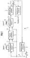
- Figure 1 shows a first measuring circuit 1 in the view as Block diagram.
- the measuring circuit 1 provides an oscillating circuit represents that from a measuring voltage generator 2, a measuring voltage conversion block 3, a first measuring module 4, one Potential adaptation stage 5 and a second measuring module 6 consists.
- an evaluation unit 7 is provided in the area between measuring voltage generator 2 and measuring voltage conversion block 3, in the area between measuring voltage generator 2 and measuring voltage conversion block 3, in the area between measuring voltage generator 2 and measuring voltage conversion block 3, an evaluation unit 7 is provided.
- the measuring voltage generator 2 generates an alternating square wave signal, that oscillates symmetrically around the potential 0 and which is referred to below as the basic signal.
- This Basic signal is output on a basic signal line 8 and arrives at the measuring voltage conversion block 3 The edges of the basic signal are shaped so that there is a sine wave results, referred to below as the measurement signal becomes.
- This measurement signal is output on the measurement signal line 9.
- the measurement signal then arrives at the first measurement module 4, where it is acted upon by a first gas sensor element 10 becomes.
- the measurement signal of the potential adjustment stage 5 and the second measuring module 6 fed.
- the measurement signal is influenced by the first measurement module 4 and superimposed by a first measurement component on a first Measurement output line 11 to the potential adaptation level 5 issued.
- the measurement signal is subtracted from this signal again, so that on a potential adjustment line 12 only the mean-free one Share of the first measurement module 4 is output.
- the second gas sensor element acts on the second measuring module 6 13 also the measurement signal from the measurement signal line 9 and there is on a second output line 14 out.
- the portion is also on the second output line 14 the change in the measurement signal by the second measurement module 6 issued.
- Due to the retroactive effect of this information on the measuring voltage generator 2 arises in the first Measuring circuit 1 is a fundamental frequency, which of the respective instantaneous resistance of the first gas sensor element 10 and of the second gas sensor element 13 depends.
- This fundamental frequency is detected by the evaluation unit 7, which with the Basic signal line 8 is connected.
- the evaluation unit 7 has an output 15 for outputting the measurement result on, from a device not shown here, such as air conditioning can be scanned.
- Figure 2 shows a second measuring circuit 20, the regarding their basic structure essentially with the first Measuring circuit 1 from Figure 1 corresponds. Same assemblies the same reference numbers are therefore given.
- the components of the second measuring circuit 20 the following structure.
- the first measuring module 4 has a first operational amplifier 21, which acts as an integrator with one in the feedback branch capacitor connected between output and inverting input CkNo is provided.
- the first operational amplifier 21 is connected to the first output line 11 in connection with the potential adaptation stage 5.
- the RMaxNo and RMinNo resistors becomes the minimum and maximum frequency of the second measuring circuit 20 even if the first changes dramatically Gas sensor element 10 due to a sudden and strong Gas loading limited.
- the ratios of the three resistors RMinNo, RMaxNo and RNo are chosen so that both at extreme low impedance as well as extreme High resistance of the resistance RNo of the gas sensor element 10 the group resistance of the resistors RMinNo, RMaxNo and RNo always within an easy-to-calculate area remains. This ensures that the frequency cannot shift the output signal into a range, the one downstream of the recording area Evaluation unit lies.
- the potential adjustment stage 5 has a second operational amplifier 22 on that as a subtractor with a resistor R4 between its output and its inverting Input is connected.
- the inverting input of the second Operational amplifier 22 is connected via a resistor R3 the supply voltage or with the first output line 11 connected.
- the non-inverting input of the second Operational amplifier 22 is connected via a resistor R4 to the Measuring voltage conversion block 3 connected.
- the exit of the second operational amplifier 22 leads via the potential adjustment line 12 to the second measuring module 6.
- the second measuring module 6 has a third operational amplifier 23 on.
- the non-inverting input of the third Operational amplifier 23 is via the potential adjustment line 12 with the output of the second operational amplifier 22 the potential adjustment level 5 connected.
- In the return line between the output of the third operational amplifier 23 and its inverting input is an arrangement of the second gas sensor element 13, one connected in series Resistance RMinHc as well as a parallel resistance RMaxHc provided.
- the inverting input of the third Operational amplifier 23 is via a resistor RkHc connected to the system ground.
- the RMinHc and RMaxHc resistors ensure that both with extreme low impedance as well as with extreme High resistance of the second gas sensor element 13 is the group resistance of the resistors RMinHc, RMaxHc and RHc des second gas sensor element 13 always within a simple area to be calculated remains. This ensures that the frequency of the output signal is not in moves an area outside the shooting area the evaluation unit 7 is located.
- the fundamental frequency of the second can be set via the resistor RkHc Measuring circuit 20 as a function of the second gas sensor element 13 can be calibrated.
- the output of the third operational amplifier 23 leads over the second output line 14 to the measuring voltage generator 2.
- the measuring voltage generator 2 has a fourth operational amplifier 24, whose inverting input with the second output line 14 is connected. In the return branch between its output and the non-inverting The input is a resistor R5 and a parallel one Capacitor C2 is provided. The non-inverting Input of the fourth operational amplifier 24 is also beyond connected to the system ground via a resistor R6.
- the fourth operational amplifier 24 forms a window comparator with hysteresis, which has two switching thresholds.
- the fourth operational amplifier 24 thus compares the voltages at its inverting input and at its non-inverting Input and switches accordingly to the result of the comparison, its exit to a different, predetermined value.
- the capacitor C2 causes that the output of the fourth operational amplifier 24th quickly saturates, resulting in a clean basic signal with sharp Crosses leads.
- the output of the fourth operational amplifier 24 becomes the measuring voltage conversion block via the basic signal line 8 3 fed.
- the measuring voltage conversion block 3 has a coil L1, which is connected in series with a resistor R1. Here is the input terminal of coil L1 with the basic signal line 8 connected.
- the measuring voltage conversion block 3 has continue to have a resistor R2 in series with the resistor R1 is switched. Is parallel to resistor R2 a capacitor C1 is switched. Here is the other connection of the resistor R2 connected to the system ground.
- a measurement signal line 9 provided with the non-inverting connection of the first operational amplifier 21 is connected.
- a line between resistor R1 and resistor R2 provided that through a resistor R4 with the inverting Input of the operational amplifier 22 is connected.
- the evaluation unit 7 For sampling the frequency with which the second measuring circuit 20 vibrates during operation, the evaluation unit 7 with the Basic signal line 8 connected.
- the second measuring circuit 20 provides one for the use of a Double sensor suitable oscillator, among other things for evaluation the quality of air.
- the output signal of the measuring voltage generator 2 is a square wave with constant Amplitude, its amplitude being the amplitude of the supply voltage corresponds since it is generated by a comparator becomes.
- This square wave signal is generated with the help of the measuring voltage conversion block 3 weakened to an amplitude of approximately 0.5 volts.
- the measuring voltage conversion block 3 provides one Second-order low-pass filter, which also allows the steep signal edges of the generated by the measuring voltage generator 2 Attenuate square wave signal.
- This signal will be the first Gas sensor element 10 supplied. On the gas sensor element 10 therefore there is a defined, constant AC voltage which is independent of the surrounding gas composition.
- the gas sensor element 10 is part of one of the first Operational amplifier 21 formed integrator.
- the time constant this integrator depends directly on the resistance RNo of the first gas sensor element 10.
- the smaller the resistance RNo the faster the voltage ramp rises at the output of the first operational amplifier 21.
- the ramp at the output of the first operational amplifier 21 becomes a Comparator with hysteresis led by the fourth operational amplifier 24 is formed. Because its output in turn controls the measuring voltage of the gas sensor elements 10 and 13, the loop is closed and the circuit swings.
- the Vibration frequency depends directly on the speed the voltage ramp at the amplifier output of the third operational amplifier 23 and thus from the resistance RHc of the second gas sensor element 13, and also from the speed of the voltage ramp at the output of the first operational amplifier 21 formed integrator and thus from the resistance RNo of the first gas sensor element 10. Die Output frequency is almost proportional to the ratio of the RNo / RHc resistors.
- the first gas sensor element 10 can be designed as a WO 3 sensor with a 20 ⁇ m electrode spacing.
- a typical operating temperature of the first gas sensor element 10 is between 300 and 350 ° C.
- the second gas sensor element 13 can be designed as a SnO 2 sensor with an activation layer, the operating temperature of which is between 300 and 350 ° C. Alternatively, it can also be designed as a Ga 2 O 3 sensor with an activation layer, which is operated at an operating temperature of 550 to 600 ° C.
- the measuring voltage generated by the measuring voltage conversion block 3 can be trapezoidal, sinusoidal or otherwise shaped be, e.g. with round flanks.
- the above-described second measuring circuit 20 describes an oscillator suitable for the use of a double sensor, among other things, for evaluating the quality of air.
- Two gas sensor elements can be used, the first of which reacts to a gas mixture with NO / NO 2 and which is very sensitive to polarization effects.
- the measurement voltage at the first gas sensor element 10 can be precisely defined with regard to the amplitude and the shape of the measurement voltage. So it can be formed symmetrically alternating and have a small, constant amplitude of about 0.5 volts.
- the second gas sensor element 13 reacts to unsaturated hydrocarbons and is less sensitive to polarization effects, so that the amplitude of the AC voltage used for the measurement does not have to be constant, but can vary, for example, between 0.1 and 5 volts.
- the second measuring circuit 20 then supplies a frequency on the basic signal line 8 which is proportional to the ratio of the concentrations of NO / NO 2 and Hc. In this way, the output frequency decreases as the NO / NO 2 concentration in the measured air increases, which means that the resistance of the first gas sensor element 10 increases. In this way, exhaust gases from diesel vehicles can be detected, for example.
- the output frequency on the basic signal line 8 is reduced also when the concentration of unsaturated hydrocarbons in a measured air rises because of that the resistance RHc of the second gas sensor element 13 sinks. This can be used to detect the emissions from gasoline vehicles be used.
- FIG. 3 shows a block diagram of a third measuring circuit 25.
- the third measuring circuit 25 is divided into a measuring voltage generator 26, in a measuring voltage conversion block 27 as well as in a measuring assembly 28.
- the measuring voltage generator 26 via a basic signal line 29 with the measuring voltage conversion block 27 connected.
- the measuring voltage conversion block 27 is via a measurement signal line 30 with the Measuring assembly 28 in connection.
- From the basic signal line 29 is an evaluation unit 31 with a basic signal on the Basic signal line 29 supplied.
- the measuring assembly 28 is provided with a gas sensor element 32, with which the concentration of a gas in a gas mixture is measured.
- the measuring voltage generator generates in the third measuring circuit 25 26 a square-wave signal on the basic signal line 29, which is called the basic signal.
- the measuring voltage conversion block 27 converts this basic signal into a measurement signal, whose alternating wave trains are sinusoidal, and there this sine signal on the measurement signal line 30 from where it is transmitted to the measuring assembly 28.
- the gas sensor element 32 acts on the measurement signal, the gas sensor element 32, whereby the measurement signal is changed.
- the changed measurement signal is via an output line 33 to the measuring voltage generator 26 transmitted.
- the evaluation unit 31 determines the respective frequency with which the third measuring circuit 25 swings.
- the measurement result is on an evaluation line 34 provided where it is used for control, for example air conditioning can be tapped.
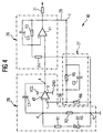
- FIG. 4 shows a circuit diagram of a fourth measuring circuit 40, which essentially corresponds to the measuring circuit from FIG. 3.
- the same assemblies and the same components are therefore the same Given reference numbers.
- the measuring voltage generator of the fourth measuring circuit 40 has a first operational amplifier 41, in the feedback branch between output and non-inverting input Resistor R4 and a capacitor C3 are connected. Of the first operational amplifier 41 provides a comparator with hysteresis The output of the first operational amplifier 41 is connected to the basic signal line 29, to which in turn the evaluation unit 31 is connected. The non-inverting Input of the first operational amplifier 41 is via a resistor R4 with a virtual system ground "e" connected. The basic signal line 29 is in the measuring voltage conversion block 27 fed, the resistor R5 with capacitor C2 connected in parallel therewith. Of the Resistor R5 is connected to the virtual via a resistor R6 System mass "e" connected. Thus, the measuring voltage transforming block 27 designed as a filter, the on a measurement signal outputs the measurement signal line 30, which leads to the measurement module 28 leads.
- the measuring assembly 28 includes a connected as an integrator second operational amplifier 42, whose supply voltage connections between an absolute mass GND and a supply voltage Vcc are connected.
- the non-inverting Input of the second operational amplifier 42 is connected to the measurement signal line 30.
- Capacitance C1 switched in a feedback branch between the output and the inverting Input of the second operational amplifier 42. It also extends between the inverting input of the second operational amplifier 42 and the virtual system ground “e" a resistor R2, too in parallel with a series connection from the gas sensor element 32 and a resistor R1 is connected.
- the third measuring circuit 40 behaves as follows. At the inverting input of the second operational amplifier 42 the measuring voltage is kept constant, the non-inverting Input of the second operational amplifier 42 is adjusted to this value. Thereby may by non-inverting input of the second operational amplifier 42 no polarization current flow, otherwise this Current on the one hand the output signal of the second operational amplifier 42 can falsify and on the other hand the gas sensor element 32 can polarize.
- a J-FET operational amplifier is preferred used, in which the polarization current located in the pA range. This current is approx. 20 pA - 200 pA and it depends on the temperature in the order of magnitude of approx. 0.2% of the measuring current. The starting point is the output voltage of the circuit Vcc and all capacitors are unloaded.
- a voltage appears at the non-inverting input of the second operational amplifier 42 U fb Vcc / 2 * (1 + R5 / R6) .
- the second operational amplifier 42 controls its output so that the voltage difference between the two inputs remains at 0 V.
- the first operational amplifier 41 is connected as a comparator with hysteresis.
- V Comparator Vcc 2nd * 1+ R 4th R 3+ R 4th falls below, the output of the first operational amplifier 41 tilts back to Vcc.
- the circuit is back in its initial state and starts to oscillate.
- the oscillation frequency depends on the value RS of the gas sensor element 32.
- Figure 5 shows a fourth measuring circuit 50 in the view as Block diagram.
- the fourth measuring circuit 50 has a first sub-measuring circuit 51 with a first gas sensor element 52 and a second Under-measuring circuit 53 with a second gas sensor element 54 on.
- the first sub-measuring circuit 51 and the second sub-measuring circuit 53 essentially correspond to the fourth measuring circuit 40 from FIG. 4.
- a counter module 55 is provided, the one Clock input 56 and a gate input 57 has.
- the exit the first sub-measuring circuit 51 is directly in the clock input 56 fed.
- the output of the second submeasuring circuit 53 is fed to a frequency divider 58, the Output is fed to the gate input 57.
- the counter 55 is a counter part Microcontroller trained.
- the first gas sensor element 52 and the second gas sensor element 54 can either be identical Sensors are used, with one sensor passivated is so that ambient gases are not going to its sensor layer can reach.
- the fifth Measuring circuit 50 is a relatively insensitive to temperature Measurement of gas concentrations can be carried out. Since both Sensors preferably have the same activation energy, the temperature behavior of the gas sensor elements also follows same function.
- the frequency divider 58 divides the output signal of the second Sub-measuring circuit 53 with a division factor n the counter reading of counter 55 is directly related to the ratio the frequencies of the first sub-measuring circuit 51 and the second Submeasuring circuit 53 multiplied by n.
- n the number of the frequencies of the first sub-measuring circuit 51 and the second Submeasuring circuit 53 multiplied by n.
- first gas sensor element 52 and the second gas sensor element 54 are provided as gas sensor elements, that react to different gases in a gas mixture, compensation for a masking effect can then be carried out in the same way be effected.
- the fifth measuring circuit 50 from FIG. 5 it is necessary the first sub-measuring circuit 51 and the second sub-measuring circuit 53 separated from each other by shielding, so that none Synchronization between the first sub-measuring circuit 51 and the second sub-measuring circuit 53 can take place.
Landscapes
- Chemical & Material Sciences (AREA)
- Health & Medical Sciences (AREA)
- Life Sciences & Earth Sciences (AREA)
- General Health & Medical Sciences (AREA)
- Immunology (AREA)
- Engineering & Computer Science (AREA)
- Analytical Chemistry (AREA)
- Biochemistry (AREA)
- Pathology (AREA)
- General Physics & Mathematics (AREA)
- Physics & Mathematics (AREA)
- Chemical Kinetics & Catalysis (AREA)
- Electrochemistry (AREA)
- Combustion & Propulsion (AREA)
- Food Science & Technology (AREA)
- Medicinal Chemistry (AREA)
- Investigating Or Analyzing Materials By The Use Of Electric Means (AREA)
- Investigating Or Analyzing Materials By The Use Of Fluid Adsorption Or Reactions (AREA)
Abstract
Description
- eine Meßsignalerzeugungsstufe zur Erzeugung eines alternierenden Grundsignals,
- eine Meßsignalumwandlungsstufe zur Umwandlung des Grundsignals in ein Meßsignal und
- eine Meßstufe mit dem Gas-Sensorelement,
- Figur 1
- zeigt ein Blockschaltbild einer ersten erfindungsgemäßen Meßschaltung,
- Figur 2
- zeigt einen Schaltplan einer zweiten erfindungsgemäßen Meßschaltung,
- Figur 3
- zeigt ein Blockschaltbild einer dritten erfindungsgemäßen Meßschaltung,
- Figur 4
- zeigt ein Schaltbild einer vierten erfindungsgemäßen Meßschaltung und
- Figur 5
- zeigt ein Blockschaltbild einer weiteren erfindungsgemäßen Meßschaltung.
Claims (15)
- Meßschaltung zur Ermittlung der Konzentration eines oder mehrerer Gase in einem Gasgemisch, die die folgenden Merkmale aufweist:wobei der Signalgenerator (2; 26) so ausgebildet ist, daß das Gas-Sensorelement (32) bzw. die Gas-Sensorelemente (10, 13; 52, 54) mit einem Meßsignal beaufschlagbar ist, dessen Ableitung nach der Zeit im wesentlichen stetig verläuft.einen Schwingkreis mit veränderlicher Eigenfrequenz, der wenigstens ein Gas-Sensorelement (10, 13; 32; 52, 54) mit variablem Widerstand umfaßt, wobei sich der Widerstand des Gas-Sensorelements (10, 13; 32; 52, 54) in Abhängigkeit der Konzentration des Gases bzw. der Gase in dem Gasgemisch verändert,wenigstens einen Signalgenerator (2; 26), der das Gas-Sensorelement (32) bzw. die Gas-Sensorelemente (10, 13; 52, 54) mit einem alternierenden Meßsignal beaufschlagt, dessen Grundfrequenz von der Größe des Widerstands des Gas-Sensorelements (32) bzw. der Gas-Sensorelemente (10, 13; 52, 54) abhängt,
- Meßschaltung nach Anspruch 1,
dadurch gekennzeichnet, daß
der Signalgenerator (2; 26) so ausgebildet ist, daß das Gas-Sensorelement (32) bzw. die Gas-Sensorelemente (10, 13; 52, 54) mit einem Meßsignal beaufschlagbar ist, dessen Ableitung nach der Zeit über den Meßbereich des Gas-Sensorelements (32) bzw. des Gas-Sensorelemente (10, 13; 52, 54) im wesentlichen stetig verläuft. - Meßschaltung zur Ermittlung der Konzentration eines oder mehrerer Gase in einem Gasgemisch, die die folgenden Merkmale aufweist:dadurch gekennzeichnet, daßeinen Schwingkreis mit veränderlicher Eigenfrequenz, der wenigstens ein Gas-Sensorelement (10, 13; 32; 52, 54) mit variablem Widerstand umfaßt, wobei sich der Widerstand des Gas-Sensorelements (32) bzw. der Gas-Sensorelemente (10, 13; 52, 54) in Abhängigkeit der Konzentration des Gases bzw. der Gase in dem Gasgemisch verändert,wenigstens einen Signalgenerator (2; 26), der das Gas-Sensorelement (32) bzw. die Gas-Sensorelemente (10, 13; 52, 54) mit einem alternierenden Meßsignal beaufschlagt, dessen Grundfrequenz von der Größe des Widerstands des Gas-Sensorelements (32) bzw. der Gas-Sensorelemente (10, 13; 52, 54) abhängt,
der Signalgenerator (2; 26) so ausgebildet ist, daß das Gas-Sensorelement (32) bzw. die Gas-Sensorelemente (10, 13; 52, 54) mit einem Meßsignal beaufschlagbar ist, dessen Amplitude und/oder Form über den Meßbereich des Gas-Sensorelements (32) bzw. der Gas-Sensorelemente (10, 13; 52, 54) im wesentlichen konstant ist. - Meßschaltung zur Ermittlung der Konzentration eines oder mehrerer Gase in einem Gasgemisch, die wenigstens ein Gas-Sensorelement (10, 13; 32; 52, 54) mit variablem Widerstand aufweist, dessen Widerstand sich in Abhängigkeit der Konzentration eines Gases in dem Gasgemisch verändert,
wobei die Meßschaltung die folgenden Stufen aufweist:wobei ferner die Meßsignalerzeugungsstufe (2; 26) und/oder die Meßsignalumwandlungsstufe (3; 27) und die Meßstufe (4, 6; 28) so zusammengeschaltet sind, daß diese einen Schwingkreis bilden, dessen charakteristische Schwingungseigenschaften sich mit der Veränderung des Widerstands des Gas-Sensorelements (10, 13; 32; 52, 54) ändert.eine Meßsignalerzeugungsstufe (2; 26) zur Erzeugung eines alternierenden Grundsignals,eine Meßsignalumwandlungsstufe (3; 27) zur Umwandlung des Grundsignals in ein Meßssignal, undeine Meßstufe (4, 6; 28) mit dem Gas-Sensorelement (10, 13; 32; 52, 54), - Meßschaltung nach Anspruch 4,
dadurch gekennzeichnet, daß
die Meßsignalerzeugungsstufe (2; 26) einen als Fensterkomparator mit Hysterese ausgebildeten Operationsverstärker (24; 41) aufweist. - Meßschaltung nach Anspruch 4 oder Anspruch 5,
dadurch gekennzeichnet, daß
die Meßsignalumwandlungsstufe (3; 27) als Bandpaßfilterstufe (L1, C1, R1, R2) ausgebildet ist. - Meßschaltung nach einem der Ansprüche 4 bis 6,
dadurch gekennzeichnet, daß
die Meßstufe (4; 28) einen als Integrator geschalteten Operationsverstärker (21; 42) aufweist, dessen erster Eingang mit dem Gas-Sensorelement (10; 32; 52, 54) verbunden ist und dessen zweiter Eingang mit dem Ausgang der Meßsignalumwandlungsstufe (3; 27) verbunden ist. - Meßschaltung nach Anspruch 9,
dadurch gekennzeichnet, daß
das Gas-Sensorelement als hochohmiges Halbleitergassensorelement (10; 32; 52, 54) ausgebildet ist. - Meßschaltung nach Anspruch 7 oder Anspruch 8,
dadurch gekennzeichnet, daß
in einem Rückführzweig zwischen dem Ausgang und einem Eingang des Operationsverstärkers (21; 42) eine Kapazität (CkNo; C1) vorgesehen ist. - Meßschaltung nach einem der Ansprüche 4 bis 6,
dadurch gekennzeichnet, daß
die Meßstufe (6) einen als Verstärker geschalteten Operationsverstärker (23) aufweist, dessen erster Eingang mit dem Ausgang der Meßsignalumwandlungsstufe (3; 27) verbunden ist, wobei in einem Rückführzweig zwischen dem Ausgang und einem Eingang des Operationsverstärkers (23) ein Gas-Sensorelement (13) vorgesehen ist. - Meßschaltung nach Anspruch 10,
dadurch gekennzeichnet, daß
das Gas-Sensorelement als niederohmiges Halbleitergassensorelement (13) ausgebildet ist. - Meßschaltung zur Ermittlung der Konzentration eines oder mehrerer Gase in einem Gasgemisch, die ein erstes Gas-Sensorelement (10) mit variablem Widerstand sowie ein zweites Gas-Sensorelement (13) mit variablem Widerstand aufweist, deren Widerstände sich jeweils in Abhängigkeit der Konzentration unterschiedlicher Gase in dem Gasgemisch verändern,
wobei die Meßschaltung die folgenden Stufen aufweist:wobei weiterhin die Meßsignalerzeugungsstufe (2) und/oder die Meßsignalumwandlungsstufe (3) sowie die erste Meßstufe (4) und die zweite Meßstufe (6) so zusammengeschaltet sind, daß diese einen Schwingkreis bilden, dessen charakteristische Schwingungseigenschaften sich mit der Veränderung des Widerstands des ersten Gas-Sensorelements (10) und/oder des zweiten Gas-Sensorelements (13) ändert.eine Meßsignalerzeugungsstufe (2) zur Erzeugung eines alternierenden Grundsignals, undeine Meßsignalumwandlungsstufe (3) zur Umwandlung des Grundsignals in ein Meßssignal,eine erste Meßstufe (4) mit dem ersten Gas-Sensorelement (10),eine zweite Meßstufe (6) mit dem zweiten Gas-Sensorelement (13), - Meßschaltung nach Anspruch 12,
dadurch gekennzeichnet, daß
wobei ferner der Ausgang der Meßsignalumwandlungsstufe (3) mit dem Eingang der ersten Meßstufe (4) in Verbindung steht und der Ausgang der ersten Meßstufe (4) mit dem Eingang der zweiten Meßstufe (6) in Verbindung steht. - Meßschaltung nach Anspruch 13,
dadurch gekennzeichnet, daß
zwischen erster Meßstufe (4) und zweiter Meßstufe (6) eine Potentialanpassungsstufe (5) vorgesehen ist, die so ausgebildet ist, daß ein Anteil des Meßsignals am Ausgang der ersten Meßstufe (4) unterdrückbar ist. - Meßschaltung nach Anspruch 14,
dadurch gekennzeichnet, daß
die Potentialanpassungsstufe (5) einen als Subtrahierer geschalteten zweiten Operationsverstärker (22) aufweist, dessen erster Eingang mit dem Ausgang der ersten Meßstufe (4) verbunden ist und dessen zweiter Eingang mit dem Ausgang der Meßsignalumwandlungsstufe (3) verbunden ist, wobei in einem Rückführzweig zwischen dem Ausgang und einem Eingang des zweiten Operationsverstärkers (22) ein Widerstand (R3) vorgesehen ist.
Applications Claiming Priority (2)
| Application Number | Priority Date | Filing Date | Title |
|---|---|---|---|
| DE19811069A DE19811069C2 (de) | 1998-03-13 | 1998-03-13 | Meßschaltung zur Ermittlung der Konzentration eines oder mehrerer Gase in einem Gasgemisch |
| DE19811069 | 1998-03-13 |
Publications (2)
| Publication Number | Publication Date |
|---|---|
| EP0942281A2 true EP0942281A2 (de) | 1999-09-15 |
| EP0942281A3 EP0942281A3 (de) | 2002-03-20 |
Family
ID=7860869
Family Applications (1)
| Application Number | Title | Priority Date | Filing Date |
|---|---|---|---|
| EP99103014A Withdrawn EP0942281A3 (de) | 1998-03-13 | 1999-02-15 | Messschaltung zur Ermittlung der Konzentration eines oder mehrerer Gase in einem Gasgemisch |
Country Status (2)
| Country | Link |
|---|---|
| EP (1) | EP0942281A3 (de) |
| DE (1) | DE19811069C2 (de) |
Cited By (5)
| Publication number | Priority date | Publication date | Assignee | Title |
|---|---|---|---|---|
| EP1109012A3 (de) * | 1999-12-09 | 2002-02-20 | Vaisala Oyj | Messmethode und System für einen Feuchtigkeits- oder Gaskonzentrationssensor |
| WO2005124327A1 (en) * | 2004-06-21 | 2005-12-29 | Telecom Italia S.P.A. | Physical quantity, particularly humidity detection device, and related detecting method |
| RU2275625C1 (ru) * | 2004-11-29 | 2006-04-27 | ГОУ ВПО Северо-Кавказский горно-металлургический институт (Государственный технологический университет) (СКГМИ (ГТУ) | Способ измерения концентрации веществ в средах |
| WO2009025648A1 (en) * | 2007-08-22 | 2009-02-26 | Cardiomems, Inc. | Loosely-coupled oscillator |
| CN112784514A (zh) * | 2021-01-19 | 2021-05-11 | 东北大学 | 基于等效电路的纳米气体传感器建模方法 |
Family Cites Families (4)
| Publication number | Priority date | Publication date | Assignee | Title |
|---|---|---|---|---|
| DE2655271C2 (de) * | 1976-12-07 | 1986-02-27 | Bieler u. Lang oHG, Automation Steuer-Regeltechnik, 7590 Achern | Vorrichtung zur Messung der Gaskonzentration in mehreren Räumen |
| GB8704873D0 (en) * | 1987-03-02 | 1987-04-08 | Atomic Energy Authority Uk | Sensors |
| DE4436938A1 (de) * | 1994-04-27 | 1996-04-18 | Auto Electronics Corp | Nässe- und windgeschützter Gassensor |
| GB9408542D0 (en) * | 1994-04-29 | 1994-06-22 | Capteur Sensors & Analysers | Gas sensing resistors |
-
1998
- 1998-03-13 DE DE19811069A patent/DE19811069C2/de not_active Expired - Fee Related
-
1999
- 1999-02-15 EP EP99103014A patent/EP0942281A3/de not_active Withdrawn
Cited By (9)
| Publication number | Priority date | Publication date | Assignee | Title |
|---|---|---|---|---|
| EP1109012A3 (de) * | 1999-12-09 | 2002-02-20 | Vaisala Oyj | Messmethode und System für einen Feuchtigkeits- oder Gaskonzentrationssensor |
| WO2005124327A1 (en) * | 2004-06-21 | 2005-12-29 | Telecom Italia S.P.A. | Physical quantity, particularly humidity detection device, and related detecting method |
| US7498823B2 (en) | 2004-06-21 | 2009-03-03 | Telecom Italia S.P.A. | Physical quantity, particularly humidity detection device, and related detecting method |
| CN1973200B (zh) * | 2004-06-21 | 2011-03-30 | 意大利电信股份公司 | 特别是湿度的物理量的检测装置和相关检测方法 |
| RU2275625C1 (ru) * | 2004-11-29 | 2006-04-27 | ГОУ ВПО Северо-Кавказский горно-металлургический институт (Государственный технологический университет) (СКГМИ (ГТУ) | Способ измерения концентрации веществ в средах |
| WO2009025648A1 (en) * | 2007-08-22 | 2009-02-26 | Cardiomems, Inc. | Loosely-coupled oscillator |
| US7667547B2 (en) | 2007-08-22 | 2010-02-23 | Cardiomems, Inc. | Loosely-coupled oscillator |
| CN112784514A (zh) * | 2021-01-19 | 2021-05-11 | 东北大学 | 基于等效电路的纳米气体传感器建模方法 |
| CN112784514B (zh) * | 2021-01-19 | 2023-09-19 | 东北大学 | 基于等效电路的纳米气体传感器建模方法 |
Also Published As
| Publication number | Publication date |
|---|---|
| DE19811069C2 (de) | 2000-03-09 |
| EP0942281A3 (de) | 2002-03-20 |
| DE19811069A1 (de) | 1999-10-07 |
Similar Documents
| Publication | Publication Date | Title |
|---|---|---|
| EP1141654B1 (de) | Betreiben eines wirbelstromsensors | |
| EP1154203B1 (de) | Messeinrichtung für eine Flamme | |
| DE102004028997A1 (de) | Verfahren zur Beeinflussung der Russanlagerung auf Sensoren | |
| DE19962654B4 (de) | Luft-Kraftstoff-Verhältniserfassungsvorrichtung und -verfahren | |
| EP1616174A1 (de) | Vorrichtung zum betreiben eines gassensors | |
| EP3596453A1 (de) | Verfahren zum betreiben eines sensors zur erfassung mindestens einer eigenschaft eines messgases in einem messgasraum | |
| DE19917618A1 (de) | Meßgerät für die Dielektrizitätskonstante einer Flüssigkeit und zugehöriges Verfahren | |
| DE3531869A1 (de) | Elektromagnetischer stroemungsmesser | |
| DE60123857T3 (de) | Steuerungsvorrichtung | |
| EP1290433B1 (de) | Verfahren und vorrichtung zum betrieb einer linearen lambdasonde | |
| EP1290432B1 (de) | Vorrichtung zum messen des innenwiderstandes einer linearen lambdasonde | |
| DE19912469A1 (de) | Verfahren zur Erfassung eines Elementwiderstandes eines Gaskonzentrationssensors sowie ein Gaskonzentrationserfassungsgerät | |
| DE19811069C2 (de) | Meßschaltung zur Ermittlung der Konzentration eines oder mehrerer Gase in einem Gasgemisch | |
| EP1299623B1 (de) | Schaltungsanordnung zur kompensation von störsignalen in der regelschleife einer linearen lambdasonde | |
| EP0665428B1 (de) | Einrichtung für die Messung von Zustandsgrössen in Gasen mit zumindest einem Halbleiter-Gassensor | |
| DE2700543C2 (de) | Gasmengendurchflußmeßeinrichtung, insbesondere zur Steuerung der Kraftstoffeinspritzanlage bei inneren Brennkraftmaschinen | |
| WO2015082197A1 (de) | Steuereinheit zum betrieb einer breitband-lambdasonde | |
| EP0769142B1 (de) | Vorrichtung zum ermitteln der konzentration einer komponente in einer gasmischung | |
| EP0250028A2 (de) | Schaltungsanordnung zur Kompensation von temperatur- und nichttemperatur-bedingtem Driften eines kapazitiven Sensors | |
| DE3927833C2 (de) | Meßschaltung und Anwendung derselben, insbesondere mit induktiven Weggebern | |
| EP3818366B1 (de) | Verfahren zum betreiben eines sensors zum nachweis mindestens eines anteils einer messgaskomponente mit gebundenem sauerstoff in einem messgas | |
| DE102022210329A1 (de) | Verfahren zum Betreiben eines Sensors zum Nachweis mindestens eines Anteils einer Messgaskomponente mit gebundenem Sauerstoff in einem Messgas | |
| DE10254852A1 (de) | Schaltungsanordnung zur Sensorauswertung und Verfahren zur Auswertung mehrerer Sensoren | |
| EP0945722A2 (de) | Halbleitergassensor | |
| EP0563613A2 (de) | Anordnung zur Bestimmung eines Gaspartialdruckes in einem Gasgemisch |
Legal Events
| Date | Code | Title | Description |
|---|---|---|---|
| PUAI | Public reference made under article 153(3) epc to a published international application that has entered the european phase |
Free format text: ORIGINAL CODE: 0009012 |
|
| AK | Designated contracting states |
Kind code of ref document: A2 Designated state(s): AT BE CH CY DE DK ES FI FR GB GR IE IT LI LU MC NL PT SE |
|
| AX | Request for extension of the european patent |
Free format text: AL;LT;LV;MK;RO;SI |
|
| RAP1 | Party data changed (applicant data changed or rights of an application transferred) |
Owner name: EPCOS AG |
|
| PUAL | Search report despatched |
Free format text: ORIGINAL CODE: 0009013 |
|
| AK | Designated contracting states |
Kind code of ref document: A3 Designated state(s): AT BE CH CY DE DK ES FI FR GB GR IE IT LI LU MC NL PT SE |
|
| AX | Request for extension of the european patent |
Free format text: AL;LT;LV;MK;RO;SI |
|
| AKX | Designation fees paid | ||
| REG | Reference to a national code |
Ref country code: DE Ref legal event code: 8566 |
|
| STAA | Information on the status of an ep patent application or granted ep patent |
Free format text: STATUS: THE APPLICATION IS DEEMED TO BE WITHDRAWN |
|
| 18D | Application deemed to be withdrawn |
Effective date: 20020903 |