EP0942401A2 - Méthode et dispositif pour la fiabilité du signal dans les agencements de feu de signalisation - Google Patents
Méthode et dispositif pour la fiabilité du signal dans les agencements de feu de signalisation Download PDFInfo
- Publication number
- EP0942401A2 EP0942401A2 EP99104966A EP99104966A EP0942401A2 EP 0942401 A2 EP0942401 A2 EP 0942401A2 EP 99104966 A EP99104966 A EP 99104966A EP 99104966 A EP99104966 A EP 99104966A EP 0942401 A2 EP0942401 A2 EP 0942401A2
- Authority
- EP
- European Patent Office
- Prior art keywords
- actuators
- central unit
- display device
- display devices
- actual
- Prior art date
- Legal status (The legal status is an assumption and is not a legal conclusion. Google has not performed a legal analysis and makes no representation as to the accuracy of the status listed.)
- Granted
Links
- 238000000034 method Methods 0.000 title claims abstract description 12
- 230000011664 signaling Effects 0.000 title description 2
- 239000011159 matrix material Substances 0.000 claims description 7
- 230000005540 biological transmission Effects 0.000 claims description 2
- 238000011156 evaluation Methods 0.000 claims description 2
- 241001136792 Alle Species 0.000 abstract 1
- 206010039203 Road traffic accident Diseases 0.000 description 1
- 238000006243 chemical reaction Methods 0.000 description 1
- 238000010586 diagram Methods 0.000 description 1
- 230000000694 effects Effects 0.000 description 1
- 238000012545 processing Methods 0.000 description 1
- 238000012552 review Methods 0.000 description 1
- 238000012546 transfer Methods 0.000 description 1
- 230000001960 triggered effect Effects 0.000 description 1
Images
Classifications
-
- G—PHYSICS
- G08—SIGNALLING
- G08G—TRAFFIC CONTROL SYSTEMS
- G08G1/00—Traffic control systems for road vehicles
- G08G1/07—Controlling traffic signals
-
- G—PHYSICS
- G08—SIGNALLING
- G08G—TRAFFIC CONTROL SYSTEMS
- G08G1/00—Traffic control systems for road vehicles
- G08G1/09—Arrangements for giving variable traffic instructions
- G08G1/095—Traffic lights
Definitions
- the invention relates to a method and an apparatus for signal protection in systems with variable message signs according to the preamble of claim 1 or the preamble of claim 3.
- Variable message signs are used to influence traffic used for example on highways.
- the individual traffic signs are arranged by matrix-like Shown points of light that over light guide bundles of low-voltage lamps be illuminated.
- the variable message signs are usually not individually, but in related groups, for example a so-called gantry bridge attached across the road.
- a variable message sign hangs over each lane of the lane. From the individual variable message signs shown states must not conflict trigger, that means they must not contradict each other. Especially must not use dangerous combinations of characters - like two opposing yellow arrows, double images and garbled images appear.
- the displayed The actual status of the traffic signs must therefore be constantly monitored to avoid errors that easily lead to traffic accidents can lead to recognize in time.
- the object is achieved with a method for signal protection with the characterizing features of the claim 1 as well as with a device for signal protection the characterizing features of claim 6 solved.
- a desired state of the central unit in an advantageous manner a selected display device to the associated one Transfer the variable message sign actuator.
- the feedback about the current status of the selected one Display device is used on all actuators as well the central unit transferred.
- each actuator as well as the Central unit will display the actual statuses currently displayed Conflicts with each other checked. It is advantageous each actuator as well as the central unit are able to Display devices, their actual states conflict with each other have to switch to a safe state.
- each actuator checks its associated Display device for a match between Target and actual status and switches in the event of a deviation Display device so that a faulty as early as possible Display is prevented.
- the individual actuators are connected to each other via a control bus, that the feedback about displayed actual conditions to everyone Actuators and the central unit are transmitted. Thereby ensures that all actuators and the central unit the displayed actual states independently of each other can check for conflicts.
- each actuator is assigned switches that have an emergency shutdown circuit switch off between the actuators and the central unit can, as soon as an error between target and actual state occurs.
- the switched off emergency shutdown causes then a shutdown of the operating voltage line for everyone Display devices. This means that there are errors in the actuators ensured that the display devices too actually be turned off.
- the device is particularly simple 8 through control processors operating in the actuators and the central unit are arranged and for transmission and evaluation of the target states and the actual states are.
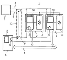
- the invention is illustrated by the only figure in the drawing explained in more detail.
- the figure shows a schematic Circuit diagram of the device for signal protection according to the invention.
- variable message signs 2 schematically two variable message sign 2 shown.
- the variable message signs 2 each have one Display device 3, for example composed of a matrix Illuminated dots illuminated by light guide bundles be, as well as an actuator 4.
- the actuators 4 control the individual display devices 3 and are over a control bus 5 connected to a central unit 6.
- To the The central unit 6 shares the display of a traffic sign Via this control bus 5 an actuator 4 the target state a currently selected display device 3.
- the target state is sent to the selected display device 3 transmitted, which in turn feedback on the displayed Current status is transferred back to the actuators 4.
- For Power supply is provided by an energy supply device 7, the actuators via a line 8 to the power supply 4 and via an operating voltage line 9 the display devices 3 powered.
- control processors 10 which shows the actual states with the target states to be displayed to compare.
- the current status of all variable message signs with the help of a so-called Checked in the actuator 4, signal protection matrix checked.
- the signal protection matrix describes which Actual states are not different at the same time Variable message signers may be displayed (Conflict), so that a traffic hazard is avoided.
- Detected a control processor 10 a deviation of the actual from Desired state or one in the signal protection matrix as dangerous marked combination of actual states (conflict), so at least the display devices involved 3 switched to a safe state, for example they are switched off. In the case of conflict, one will be opposed higher security by switching off everyone in the system 1 arranged display devices 3 achieved.
- an emergency shutdown circuit 11 which connects individual actuators 4 with the central unit 6. There are switches in each actuator and in the central unit 12 provided that are triggered in the event of an error. A switch 13 to interrupt the operating voltage line 9, the is in the emergency shutdown circuit 11, causes in the event of an error an interruption of the operating voltage line 9. This all display devices are switched off. So both a shutdown by the actuators 4 as well as one Shutdown via the operating voltage line 9 ensured.
- the line 8 for Power supply to the actuators 4, the operating voltage line 9, the control bus 5 and the emergency shutdown circuit 11 together in a cable harness from the central unit 6 to the individual variable message signs 2 led.
Landscapes
- Physics & Mathematics (AREA)
- General Physics & Mathematics (AREA)
- Traffic Control Systems (AREA)
- Inverter Devices (AREA)
- Road Signs Or Road Markings (AREA)
- Communication Control (AREA)
- Stereo-Broadcasting Methods (AREA)
Applications Claiming Priority (2)
| Application Number | Priority Date | Filing Date | Title |
|---|---|---|---|
| DE19811082 | 1998-03-13 | ||
| DE19811082 | 1998-03-13 |
Publications (3)
| Publication Number | Publication Date |
|---|---|
| EP0942401A2 true EP0942401A2 (fr) | 1999-09-15 |
| EP0942401A3 EP0942401A3 (fr) | 2000-08-30 |
| EP0942401B1 EP0942401B1 (fr) | 2004-09-22 |
Family
ID=7860880
Family Applications (1)
| Application Number | Title | Priority Date | Filing Date |
|---|---|---|---|
| EP99104966A Expired - Lifetime EP0942401B1 (fr) | 1998-03-13 | 1999-03-12 | Méthode et dispositif pour la fiabilité du signal dans les agencements de feu de signalisation |
Country Status (4)
| Country | Link |
|---|---|
| EP (1) | EP0942401B1 (fr) |
| AT (1) | ATE277394T1 (fr) |
| DE (1) | DE59910549D1 (fr) |
| DK (1) | DK0942401T3 (fr) |
Families Citing this family (1)
| Publication number | Priority date | Publication date | Assignee | Title |
|---|---|---|---|---|
| DE102005046760B4 (de) * | 2005-09-29 | 2008-09-04 | Siemens Ag | Verfahren und Vorrichtung zur Ansteuerung ein oder mehrerer Verkehrsbeeinflussungselemente |
Family Cites Families (4)
| Publication number | Priority date | Publication date | Assignee | Title |
|---|---|---|---|---|
| DE3337700A1 (de) * | 1983-10-17 | 1985-05-02 | Stührenberg, Rolf, 4930 Detmold | Vorrichtung zur signalsicherung bei lichtzeichenanlagen |
| DE3541549A1 (de) * | 1985-11-25 | 1987-05-27 | Stuehrenberg Rolf | Verfahren und vorrichtung zur signalsicherung in lichtzeichenanlagen |
| DE3805949A1 (de) * | 1988-02-25 | 1989-09-07 | Siemens Ag | Einrichtung zur teilabschaltung einer strassenverkehrssignalanlage |
| FR2647932B1 (fr) * | 1989-06-02 | 1991-09-06 | Forclum Force Lumiere Elect | Dispositif de telesurveillance de feux de carrefour et procede de mise en service d'un tel dispositif |
-
1999
- 1999-03-12 DK DK99104966T patent/DK0942401T3/da active
- 1999-03-12 AT AT99104966T patent/ATE277394T1/de not_active IP Right Cessation
- 1999-03-12 EP EP99104966A patent/EP0942401B1/fr not_active Expired - Lifetime
- 1999-03-12 DE DE59910549T patent/DE59910549D1/de not_active Expired - Fee Related
Also Published As
| Publication number | Publication date |
|---|---|
| DE59910549D1 (de) | 2004-10-28 |
| DK0942401T3 (da) | 2005-01-24 |
| EP0942401A3 (fr) | 2000-08-30 |
| EP0942401B1 (fr) | 2004-09-22 |
| ATE277394T1 (de) | 2004-10-15 |
Similar Documents
| Publication | Publication Date | Title |
|---|---|---|
| DE60023055T2 (de) | Stellwerkanlage für ein Eisenbahnsystem | |
| EP0082300B1 (fr) | Système de câblage multiplex pour véhicules | |
| EP0875810B1 (fr) | Méthode et dispositif de surveillance d'une installation comprenant plusieurs unités fonctionnelles | |
| DE19916452C2 (de) | Vorrichtung für einen Powerring | |
| DE102016100175B4 (de) | Robotersystem, welches mit einer Mehrzahl von Controllern vorgesehen ist, die eine Mehrzahl von Industrierobotern betätigen | |
| DE2701925A1 (de) | Fahrzeugsteuerungssystem mit hoher zuverlaessigkeit | |
| EP2307256A1 (fr) | Procédé et dispositif pour faire fonctionner un équipement de sécurité ferroviaire | |
| EP0330164B1 (fr) | Dispositif de mise hors circuit partielle d'un système de signalisation routière | |
| DE3910864C1 (fr) | ||
| DE69005125T2 (de) | Modularüberwachungssystem für industrielle Einrichtungen. | |
| EP0942401B1 (fr) | Méthode et dispositif pour la fiabilité du signal dans les agencements de feu de signalisation | |
| DE3223779A1 (de) | Fehlersichere adersparende lichtsignalsteuereinrichtung | |
| DE102018220092A1 (de) | Verfahren und Vorrichtung zum Absichern von automatisierten Fahrfunktionen | |
| EP1420495B1 (fr) | Installation d'une fonction de protection dans un appareil de protection d'un réseau de distribution d'électricité | |
| WO1998056635A1 (fr) | Dispositif pour commander des passages a niveau | |
| EP0148284B1 (fr) | Installation de sécurité d'une voie de roulement pour aéroports | |
| EP3383723A1 (fr) | Dispositif et procédé de commande et/ou de surveillance d'unités fonctionnelles intelligentes décentralisées agencées dans un réseau ferroviaire | |
| AT397314B (de) | Verkehrswarnsystem | |
| DE102014016018B4 (de) | Schalteinrichtung für ein Bordnetz eines Kraftfahrzeugs, Bordnetz und Kraftfahrzeug | |
| DE3219366A1 (de) | Elektronische weichensteuerung | |
| DE69125570T2 (de) | Verfahren zur Blockierung und Verriegelung bei Schalthandlungen in elektrischen Schaltanlagen | |
| WO1999008489A1 (fr) | Procede et dispositif pour maintenir a un niveau constant le courant d'un circuit en serie d'installations de balisage installees sur des aeroports ou similaires | |
| DE3127363A1 (de) | "rechnergesteuertes stellwerk" | |
| DE3205885C1 (en) | Protection circuit against flashing-light corruption | |
| DE102008003439B4 (de) | Verkehrssignalisierungsmodul, Verkehrssignalisierungssystem und Verfahren zum Betrieb eines Verkehrssignalisierungssystems |
Legal Events
| Date | Code | Title | Description |
|---|---|---|---|
| PUAI | Public reference made under article 153(3) epc to a published international application that has entered the european phase |
Free format text: ORIGINAL CODE: 0009012 |
|
| AK | Designated contracting states |
Kind code of ref document: A2 Designated state(s): AT BE CH DE DK LI NL |
|
| AX | Request for extension of the european patent |
Free format text: AL;LT;LV;MK;RO;SI |
|
| PUAL | Search report despatched |
Free format text: ORIGINAL CODE: 0009013 |
|
| AK | Designated contracting states |
Kind code of ref document: A3 Designated state(s): AT BE CH CY DE DK ES FI FR GB GR IE IT LI LU MC NL PT SE |
|
| AX | Request for extension of the european patent |
Free format text: AL;LT;LV;MK;RO;SI |
|
| RIC1 | Information provided on ipc code assigned before grant |
Free format text: 7G 08G 1/07 A, 7G 08G 1/097 B |
|
| 17P | Request for examination filed |
Effective date: 20010219 |
|
| AKX | Designation fees paid |
Free format text: AT BE CH DE DK LI NL |
|
| GRAP | Despatch of communication of intention to grant a patent |
Free format text: ORIGINAL CODE: EPIDOSNIGR1 |
|
| RTI1 | Title (correction) |
Free format text: METHOD AND DEVICE FOR SIGNAL SAFETY IN TRAFFIC LIGHT CONTROL SYSTEMS |
|
| GRAS | Grant fee paid |
Free format text: ORIGINAL CODE: EPIDOSNIGR3 |
|
| GRAA | (expected) grant |
Free format text: ORIGINAL CODE: 0009210 |
|
| AK | Designated contracting states |
Kind code of ref document: B1 Designated state(s): AT BE CH DE DK LI NL |
|
| REG | Reference to a national code |
Ref country code: CH Ref legal event code: NV Representative=s name: SIEMENS SCHWEIZ AG Ref country code: CH Ref legal event code: EP |
|
| REF | Corresponds to: |
Ref document number: 59910549 Country of ref document: DE Date of ref document: 20041028 Kind code of ref document: P |
|
| REG | Reference to a national code |
Ref country code: DK Ref legal event code: T3 |
|
| PG25 | Lapsed in a contracting state [announced via postgrant information from national office to epo] |
Ref country code: LI Free format text: LAPSE BECAUSE OF NON-PAYMENT OF DUE FEES Effective date: 20050331 Ref country code: DK Free format text: LAPSE BECAUSE OF NON-PAYMENT OF DUE FEES Effective date: 20050331 Ref country code: CH Free format text: LAPSE BECAUSE OF NON-PAYMENT OF DUE FEES Effective date: 20050331 Ref country code: BE Free format text: LAPSE BECAUSE OF NON-PAYMENT OF DUE FEES Effective date: 20050331 |
|
| PLBE | No opposition filed within time limit |
Free format text: ORIGINAL CODE: 0009261 |
|
| STAA | Information on the status of an ep patent application or granted ep patent |
Free format text: STATUS: NO OPPOSITION FILED WITHIN TIME LIMIT |
|
| 26N | No opposition filed |
Effective date: 20050623 |
|
| BERE | Be: lapsed |
Owner name: *SIEMENS A.G. Effective date: 20050331 |
|
| PG25 | Lapsed in a contracting state [announced via postgrant information from national office to epo] |
Ref country code: NL Free format text: LAPSE BECAUSE OF NON-PAYMENT OF DUE FEES Effective date: 20051001 |
|
| REG | Reference to a national code |
Ref country code: CH Ref legal event code: PL |
|
| NLV4 | Nl: lapsed or anulled due to non-payment of the annual fee |
Effective date: 20051001 |
|
| REG | Reference to a national code |
Ref country code: DK Ref legal event code: EBP |
|
| BERE | Be: lapsed |
Owner name: *SIEMENS A.G. Effective date: 20050331 |
|
| PGFP | Annual fee paid to national office [announced via postgrant information from national office to epo] |
Ref country code: DE Payment date: 20080519 Year of fee payment: 10 |
|
| PGFP | Annual fee paid to national office [announced via postgrant information from national office to epo] |
Ref country code: AT Payment date: 20090213 Year of fee payment: 11 |
|
| PG25 | Lapsed in a contracting state [announced via postgrant information from national office to epo] |
Ref country code: DE Free format text: LAPSE BECAUSE OF NON-PAYMENT OF DUE FEES Effective date: 20091001 |
|
| PG25 | Lapsed in a contracting state [announced via postgrant information from national office to epo] |
Ref country code: AT Free format text: LAPSE BECAUSE OF NON-PAYMENT OF DUE FEES Effective date: 20100312 |