EP0942490A2 - Broche de contact à fixer dans des trous métallisés de circuits imprimés - Google Patents
Broche de contact à fixer dans des trous métallisés de circuits imprimés Download PDFInfo
- Publication number
- EP0942490A2 EP0942490A2 EP99104701A EP99104701A EP0942490A2 EP 0942490 A2 EP0942490 A2 EP 0942490A2 EP 99104701 A EP99104701 A EP 99104701A EP 99104701 A EP99104701 A EP 99104701A EP 0942490 A2 EP0942490 A2 EP 0942490A2
- Authority
- EP
- European Patent Office
- Prior art keywords
- trough
- approximately
- length
- section
- deeper
- Prior art date
- Legal status (The legal status is an assumption and is not a legal conclusion. Google has not performed a legal analysis and makes no representation as to the accuracy of the status listed.)
- Withdrawn
Links
Images


Classifications
-
- H—ELECTRICITY
- H01—ELECTRIC ELEMENTS
- H01R—ELECTRICALLY-CONDUCTIVE CONNECTIONS; STRUCTURAL ASSOCIATIONS OF A PLURALITY OF MUTUALLY-INSULATED ELECTRICAL CONNECTING ELEMENTS; COUPLING DEVICES; CURRENT COLLECTORS
- H01R12/00—Structural associations of a plurality of mutually-insulated electrical connecting elements, specially adapted for printed circuits, e.g. printed circuit boards [PCB], flat or ribbon cables, or like generally planar structures, e.g. terminal strips, terminal blocks; Coupling devices specially adapted for printed circuits, flat or ribbon cables, or like generally planar structures; Terminals specially adapted for contact with, or insertion into, printed circuits, flat or ribbon cables, or like generally planar structures
- H01R12/50—Fixed connections
- H01R12/51—Fixed connections for rigid printed circuits or like structures
- H01R12/55—Fixed connections for rigid printed circuits or like structures characterised by the terminals
- H01R12/58—Fixed connections for rigid printed circuits or like structures characterised by the terminals terminals for insertion into holes
- H01R12/585—Terminals having a press fit or a compliant portion and a shank passing through a hole in the printed circuit board
Definitions
- the invention relates to a contact pin with the features of the preamble of Claim 1.
- Such a contact pin is known from EP-A-0 831 558, which is a prior art in accordance with Art 54, Paragraph 3 EPC.
- the distances between two contact zones in both Cross-sectional halves are the same and the length of the contact zones is about twice as large like this distance, so that the press-in section is elongated.
- Both bottom surfaces the troughs are contoured rectangular, while the top contours of the troughs are octagonal.
- Such a contact pin is required to be inserted into the PCB hole does not damage the metallized surface, but it does damage one ensures a springy fit that keeps it centered with high precision and a good ensures electrical connection. These properties should also be retained when the contact pin is pulled out of the circuit board hole again and again is used.
- contact pins can be divided into two groups, namely those with Subdivide symmetrical cross section and those with asymmetrical cross section.
- a symmetrical cross-section means a mirror-image formation to two orthogonal Axes.
- the bridge contains the center of the perimeter connecting the contact zones.
- the contact pin according to EP-A-0 831 558 belongs to the second group.
- EP-A-0209936 belongs to the first group.
- the press-in section gains elasticity due to the flexibility of the leg ends. Uniform elastic deformation of all four leg ends are practically impossible to achieve even with high-precision production. At the Inserting the pin into the circuit board hole therefore leads to circumferential shifts the contact zones in the PCB hole with the result that a concentric fit is not is possible.
- EP-A-0234235 also belongs to the first group.
- the contact pin has an X-shaped Press-in zone, since the leg arms extend essentially radially, they can extend do not bend when inserting the pin into the PCB hole.
- the elasticity tries can be reached here through an additional longitudinal slot in the bridge.
- the group of asymmetrical cross-sections in the press-in section includes in addition to the EP-A-0831558 mentioned at the beginning, in which the bridge is flat in the central region is EP-A-0059462, DE-C-3210348 and DE-A-3804041.
- the latter is common Documents that the bridge between the two H-legs angled or bent is. The bend or curvature of the bridge increases when the contact pin is inserted. The bridge deforms like a curved leaf spring. However, the goal a parallel displacement of the two legs with mutual approximation at Inserting the press-in zone in the PCB hole not reached because of Resistance to deformation due to the asymmetrical design in the press-in zone is different on both sides.
- a contact pin of basically H-shaped Cross section in the press-in zone and a curved bridge between the both ribs have a high permanent elasticity behavior.
- the four contact zones a cuboid, whose length measured in the direction of the shaft is approximately that Corresponds to cross-sectional diagonals.
- the press-in zone length would have to be appropriate be reduced. But it turns out that with the previous training of Press-fit cross-section of this target is not achievable.
- the object of the invention is so a contact pin of the type mentioned train that the elastic clamping fit of the contact pin not only improves, but is designed so that it can also be used in much thinner circuit boards, e.g. 0.8 mm thickness secure attachment allowed.
- the four contact zones preferably form the corner points of a trapezoid, the larger trapezoidal side is assigned to the deeper depression of the press-in section, like this is known per se from DE-A-3220781. Swiveling occurs during the press-in process of the ribs, with the two further apart contact zones on the concave side of the bridge closer together, with the result that the four Contact zones now form the corner points of a rectangle. Thanks to the angular to the Longitudinal axis lying connecting surfaces on both sides adjacent to the Axially parallel side surfaces of both troughs is the axis parallelism of the four contact zones ensured.
- the invention has Pin an extremely compact press-in zone, in which the contact zone length is smaller than that is the smallest distance between two of the four contact zones.
- the four axially parallel axes ensure a length of only about 0.5 mm Contact zones for a secure press fit of the contact pin even in thin circuit boards of only 0.8 mm thickness.
- the insertion section of the contact pin is therefore still partially inside the PCB hole, so that sufficient chip space is created.
- the on the taper adjoining the contact zone area also still lies partly in the circuit board area, so that here the so-called push button effect Wear comes.
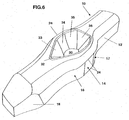
- each trough has an eight-sided circumferential wall that fits into the respective radius Bottom surface of the bridge runs in. A corresponding arch transition takes place between the trough peripheral surfaces and the outer surfaces of the ribs.
- the two hollows are designed differently and so the bottom surface of the deep trough has an elongated Octagon with pointed blunt end pointing in the direction of the pin tip, while the eight circumferential surfaces of the shallower trough in the area of the bottom surface rather symmetrical elongated octagon, approximating oval shape.
- the side surfaces of the deeper trough are each in the form of an oblique trapezoid with a Average edge length of at least approximately one third of that in the Trough center longitudinal plane along the bottom surface measured length of the deeper trough formed and these side surfaces have an edge length of at least on the top side approx. 0.25 mm and a length of 0.3 mm on the bottom.
- the Side surfaces of the shallower trough have longer top and bottom edges than that Side surfaces of the deeper trough and preferably the smallest edge length is Side surfaces of the shallower trough at least approximately 50% of that in the Longitudinal median level measured ground level.
- the edge length of the deck Side surfaces of the flatter trough corresponds to the contact zone length at the Rib outer sides, and this contact zone length is preferably 0.5 mm.
- the Side surfaces of both troughs are convexly curved at surface height and the chord height the surface curvature is greater on the side surfaces of the shallower trough than on the Side surfaces of the deeper trough.
- the chord height of the side surfaces is deeper trough about 0.03 mm.
- the corresponding chord height of the side surfaces of the shallower trough is at least approximately twice as large.
- the longitudinal median plane measured level of the lower trough at least approximately twice as large is like the length of the bottom surface of this trough measured in this plane.
- An important Characteristic of the deeper trough is that the width of the side surfaces at the expense of Width of the dome-side connecting surfaces is reduced.
- the top edge length of the dome-side connecting surfaces of the deeper trough at least approximately equal to that measured in the median longitudinal plane Floor length.
- These are long connecting surfaces of the deeper trough preferably flat and form an angle of at least one another approximately 70 °.
- These connection surfaces on the dome side form the inlet area the press-in zone. They close the very narrow gusset-like end face on the dome side on.
- These connecting surfaces are set at approximately 10 ° to the vertical.
- An arrangement the invention can still be seen in that the shaft-side connecting surfaces of the deeper trough contoured trapezoidal and at least approximately under 20 ° to the axis are arranged.
- the four rectilinear contact zones also define a straight prism trapezoidal base area and the length of the prism measured in the longitudinal direction of the shaft is smaller than its dimensions, such as width and height, measured at right angles to it.
- the length of the diagonals of the prism cross section is preferably at least that Three times the prism length measured in the axial direction.
- the length of the Injection section upstream insertion section at least approximately 80% of Length of the straight contact zones of the press-in section.
- an outlet section tapering to the shaft diameter whose length is at least approximately half the contact zone length of the Press-in section is.
- the insertion section and the outlet section are each approximately half inside the PCB hole.
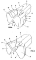
- a contact pin 10 with shaft 12 and press-in section 14, insertion section 16 and Outlet section 17 and pin tip 18 has the in FIG. 4 shown cross section, the two Ribs 20 and a bridge 22 connecting them.
- These four contact zones 24 form in Cross section of the end points of a trapezoid Relating to the curved bridge 22 is on the concave side of a deep trough 26 and on the opposite convex side a flat trough 28 is formed.
- the bridge 22 itself is asymmetrical to the shaft axis namely shifted towards the lower half. In the bridge 22 is the bending zone Ribs 20 of the press-in section 14.
- the two contact zones 24 in the upper half of the lower trough 26 Cross sections have a distance from each other that is greater than the distance of Contact zones 24 in the lower half containing the shallower trough 28.
- the exact Contact zones 24 running parallel to the axis thus also define a straight prism Trapezoidal cross-section.
- the outer rib surfaces are flat and form an angle of approx. 8 ° together.
- FIG. 5 is the deformation of the press-in section 14 when inserting the Contact pin illustrated in a circuit board hole 25.
- the two ribs 20 pivot thereby on the side of the deeper recess 26 inwards, so that the contact zone distance both sides of the bridge 22 is approximately the same.
- the narrow arched bridge 22 ensures the permanent elasticity of the press-in section 14.
- the deeper trough 26 has an octagonally contoured bottom surface 30 which can be joined to a transition radius adjoins an eight-part circumferential surface consisting of a dome-side end face 32, the two opposite side faces 34 and an end face 36 on the shaft side and two connection faces 33 on the dome side and two shaft-side connecting surfaces 35 are assembled.
- Characteristic of deep trough 26 are the side surfaces 34 that run parallel to the axis the pronounced long dome-side at approximately 20 ° to the axial direction Connecting surfaces 33.
- the deep recess 26 therefore has the shape of a pin tip 18 tapered trough.
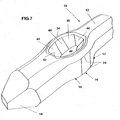
- the shallower trough 28 also has an octagonal base surface 40, a trapezoidal one dome-side end face 42, two axially parallel trapezoidal side faces 44, one Trapezoidal end face 46 on the shaft side and one lying obliquely to the shaft axis dome-side connection surfaces 43 and shaft-side connection surfaces 45.
- the Shape of the shallow trough 28 is an elongated octagon that you roughly look at fold symmetrically to a central transverse plane.
- the deep trough 26 can be described as pear-shaped or teardrop-shaped, the flat trough 28 can be described like an oval.
- cover-side contour of the trough at least approximates the base-side contour is geometrically similar. In any case, both the deck side and the bottom contours of both hollows octagon.
- the individual areas of both troughs are described below.
- the dome side End face 32 of the deeper depression 26 is flat, that is to say has no curvature. It runs approximately at an angle of 45 ° to the level of the floor surface 30 a narrow trapezoidal surface with a bottom edge length of 0.05 mm and one top edge length of 0.15 mm.
- the two coupling surfaces 33 on the dome side the lower trough 26 are skewed in the room. With the vertical they form one Angle of approx. 10 ° and together they form an angle of approx. 70 ° - in the Cover surface level measured - a.
- the bottom edge length of this dome-side Connection surfaces 33 is 0.3 mm and the top edge length is 0.75 mm.
- the material displaced by these comparatively long connecting surfaces 33 forms the Insertion section 16 of the contact pin 10.
- the two side surfaces 34 of the deeper recess 26 are slightly convex in their vertical section with a chord height of approx. 0.03 mm. she lie parallel to the shaft axis and are at an angle of approx. 15 ° to the vertical employed.
- the diagonal dimension of the press-in section 14 is generated with these surfaces, that is required to cover the hole tolerances in the circuit board.
- This Side surfaces are also used to create the straight contact zones 24 responsible.
- These side surfaces 34 are trapezoidal and taper from below slightly upwards, the lower edge length 0.30 mm and the upper edge length Is 0.25 mm.
- the shaft-side connecting surfaces 35 of the deeper recess 26 are in the Vertical section also slightly convex with a tendon height of 0.03 mm. This Surfaces are in connection with the end face 36 on the shaft side to be described for the creation of the outlet area and for the required "push button effect" responsible. These connecting surfaces 35 are at about 45 ° to the shaft axis slanted. Thanks to these connecting surfaces, the outlet area 17 is also connected sufficient wall thickness. The bottom edge length of this Connecting surfaces 35 is 0.20 mm and the top edge length 0.40 mm.
- the end face 36 of the deeper recess 26 on the shaft side lies transversely to the shaft axis and is light convex with 0.06 mm chord height.
- the bottom edge length is 0.10 mm and the top edge length 0.55 mm.
- the bottom surface 30 of the deeper trough 26 is over hers entire length concavely curved, and - as already mentioned - adjoins the Trough circumferential surfaces.
- the length of the bottom surface 30 between the two End faces 32, 36 is 0.75 mm.
- the dome-side end face 42 of the flatter trough 28 is transverse to the direction of the shaft and is set to the vertical at approx. 10 °. This end face 42 has no curvature.
- the Bottom edge length is 0.20 mm and the top edge edge length is 0.40 mm.
- the itself the dome-side end face 42 adjoining two dome-side Connecting surfaces 43 each form an angle of approximately 20 ° with the shaft axis and are with the dome-side connecting surfaces 33 of the deeper recess 26 for the Forming the insertion section 16 responsible.
- the bottom edge length of the dome-side connecting surfaces 43 is approximately 0.25 mm and the top side Edge length is 0.40 mm.
- the two side surfaces 44 are parallel to the axis. they are slightly convex in height with a tendon height of approx.
- the Bottom edge length is 0.40 mm and the top edge length is 0.50 mm.
- the bottom edge length is 0.20 mm and the top edge length is approximately 0.30 mm.
- the end face 46 on the shaft side is in turn trapezoidal in shape and lies transverse to the pin axis and their bottom edge length is 0.20 mm and the top edge length is 0.55 mm.
- bottom surface 40 is convex over the entire length and this curvature passes over narrow radii into the side and connecting surfaces.
- the middle Floor length between the two end faces is 0.80 mm.
- FIG. 10 illustrates the seat of the contact pin 10 in the hole 50 of a printed circuit board 52 a plate thickness of 0.8 mm.
- the pin is with a top view of the deeper recess 26 shown.
- the length of the four straight axially parallel contact zones 24 of the Press-in section 14 is 0.50 mm.
- This press-in section 14 is the Insertion section 16 upstream with a length of 0.40 mm, which is about half in the PCB hole 50 has space so that enough chip space for the displaced tin material is created.
- the outlet section 17 is also about half within the PCB hole 50, so that the "push button effect" can come into effect here.
Landscapes
- Coupling Device And Connection With Printed Circuit (AREA)
- Multi-Conductor Connections (AREA)
Applications Claiming Priority (2)
| Application Number | Priority Date | Filing Date | Title |
|---|---|---|---|
| DE19810897 | 1998-03-13 | ||
| DE19810897A DE19810897C1 (de) | 1998-03-13 | 1998-03-13 | Kontaktstift zur lötfreien Befestigung in metallisierten Löchern von Leiterplatten |
Publications (2)
| Publication Number | Publication Date |
|---|---|
| EP0942490A2 true EP0942490A2 (fr) | 1999-09-15 |
| EP0942490A3 EP0942490A3 (fr) | 2002-01-02 |
Family
ID=7860749
Family Applications (1)
| Application Number | Title | Priority Date | Filing Date |
|---|---|---|---|
| EP99104701A Withdrawn EP0942490A3 (fr) | 1998-03-13 | 1999-03-10 | Broche de contact à fixer dans des trous métallisés de circuits imprimés |
Country Status (2)
| Country | Link |
|---|---|
| EP (1) | EP0942490A3 (fr) |
| DE (1) | DE19810897C1 (fr) |
Cited By (1)
| Publication number | Priority date | Publication date | Assignee | Title |
|---|---|---|---|---|
| CN111755858A (zh) * | 2019-03-28 | 2020-10-09 | 株式会社自动网络技术研究所 | 压配合端子、基板用连接器及带基板的连接器 |
Families Citing this family (2)
| Publication number | Priority date | Publication date | Assignee | Title |
|---|---|---|---|---|
| DE202016008607U1 (de) * | 2015-05-06 | 2018-08-23 | PPM - Pforzheimer Präzisions Mechanik GmbH + Co. KG | Lötfreier Platinensteckkontakt |
| EP3688844B1 (fr) * | 2017-09-28 | 2023-11-29 | Interplex Industries, Inc. | Contact pourvu d'un élément de fixation à ajustement par pression |
Family Cites Families (13)
| Publication number | Priority date | Publication date | Assignee | Title |
|---|---|---|---|---|
| DE3266605D1 (en) * | 1981-03-02 | 1985-11-07 | Thaler Harmuth F | Pressurized connection pin |
| DE3210348C1 (de) * | 1982-03-20 | 1983-08-11 | Harting Elektronik Gmbh, 4992 Espelkamp | Stiftfoermiges Kontaktelement zur Befestigung in Leiterplatten-Bohrungen |
| DE3220781A1 (de) * | 1982-06-02 | 1983-12-08 | Harting Elektronik Gmbh, 4992 Espelkamp | Kontaktelement zur loetfreien befestigung in leiterplatten-bohrungen |
| DE3241061C2 (de) * | 1982-11-06 | 1986-04-10 | Erni Elektroapparate Gmbh, 7321 Adelberg | Elastischer Einpreßstift für die lötfreie Verbindung der Wickelpfosten elektrischer Steckverbinder o.dgl. mit durchkontaktierten Leiterplatten sowie Verfahren zu seiner Herstellung |
| NL8502046A (nl) * | 1985-07-16 | 1987-02-16 | Du Pont Nederland | Elektrische contactpen voor printplaat. |
| GB2186124A (en) * | 1986-01-30 | 1987-08-05 | Plessey Co Plc | Contact pin |
| JPH0431740Y2 (fr) * | 1986-09-26 | 1992-07-30 | ||
| DE3804041A1 (de) * | 1988-02-10 | 1989-08-24 | Harting Elektronik Gmbh | Stiftfoermiges kontaktelement zur befestigung in leiterplatten-bohrungen |
| US4878861A (en) * | 1988-11-01 | 1989-11-07 | Elfab Corporation | Compliant electrical connector pin |
| DE4002486A1 (de) * | 1990-01-29 | 1991-08-08 | Polytronic Kunststoff Elektro | Kontaktelement mit einer einpresszone |
| JP3250902B2 (ja) * | 1994-03-04 | 2002-01-28 | 富士通株式会社 | プレスフィットピン |
| JP2929176B2 (ja) * | 1996-09-20 | 1999-08-03 | モレックス インコーポレーテッド | プレスフィットピン |
| US6098281A (en) * | 1996-11-06 | 2000-08-08 | Weidmuller Interface Gmbh & Co. | Electrical pins and method for their insertion into apertures of a circuit board |
-
1998
- 1998-03-13 DE DE19810897A patent/DE19810897C1/de not_active Expired - Fee Related
-
1999
- 1999-03-10 EP EP99104701A patent/EP0942490A3/fr not_active Withdrawn
Cited By (1)
| Publication number | Priority date | Publication date | Assignee | Title |
|---|---|---|---|---|
| CN111755858A (zh) * | 2019-03-28 | 2020-10-09 | 株式会社自动网络技术研究所 | 压配合端子、基板用连接器及带基板的连接器 |
Also Published As
| Publication number | Publication date |
|---|---|
| DE19810897C1 (de) | 1999-08-19 |
| EP0942490A3 (fr) | 2002-01-02 |
Similar Documents
| Publication | Publication Date | Title |
|---|---|---|
| EP0236260B1 (fr) | Elément de construction pour maquettes, en particulier pour jeux de construction | |
| DE69738308T2 (de) | Kontaktstift mit in entgegen gesetzter Richtung orientierte Verankerungsflügel und Steckerelement | |
| DE4018164C2 (de) | Schneidklemm-Kontakt | |
| DE69204024T2 (de) | Elektrischer Flachbauverbinder. | |
| DE10252802B4 (de) | Aufzunehmendes Flachsteckerteil, Flachstecker und Verfahren zum Ausbilden bzw. Herstellen desselben | |
| DE10321348B4 (de) | Steckverbinder | |
| DE68917080T2 (de) | Elektrischer Verbinder für elektronische Gedächtniskarten, Verfahren der Verwirklichung eines derartigen Verbinders und Lese-Schreibvorrichtung mit diesem Verbinder. | |
| DE69417988T2 (de) | Leiterplattenrandverbinder mit Kontakten von verminderten Teilung | |
| DE2414640B2 (de) | Elektrischer Verbinder mit einer metallischen Anschlußklemme | |
| DE2435461C2 (de) | Elektrischer Kontaktstift | |
| DE2621634A1 (de) | Prismatisches spielzeugbauelement aus kunststoff | |
| DE68923016T2 (de) | Elektrischer Endstückstift mit nachgiebigem Teil. | |
| DE3221844C2 (fr) | ||
| EP0023296B1 (fr) | Procédé de fabrication d'une partie de serrage sur un élément en forme de tige susceptible d'être montée à force dans une ouverture | |
| DE2925590A1 (de) | Elektrische kontaktanordnung fuer einen an einer gedruckten schaltung anschliessbaren verbinder | |
| DE10214603A1 (de) | Vereinigbares Anschlußpaßstück, Konstruktion zum Vereinigen bzw. Verbinden einer Vielzahl von Anschlußpaßstücken und Verfahren | |
| DE2700617B2 (de) | Verfahren zum Herstellen eines elektrischen Bauteils mit Anschlußfahnen und mit diesem Verfahren hergestellter Bauteil | |
| DE29718565U1 (de) | Kontaktstift | |
| DE60027079T2 (de) | Druckkontakt-Verbinder | |
| DE69600812T2 (de) | Elektrischer Verbinder mit Montagepfosten | |
| DE19810897C1 (de) | Kontaktstift zur lötfreien Befestigung in metallisierten Löchern von Leiterplatten | |
| AT405627B (de) | Vertikalverbindung zwischen zwei bauelementen | |
| EP0100922B1 (fr) | Moitié d'un dispositif de connexion multipolaire | |
| DE3416968C1 (de) | Einstueckiges Kontaktelement zum Einpressen in eine ein- oder mehrlagige Leiterplatte | |
| DE68905399T2 (de) | Elektrischer Mehrstiftsteckverbinder der Art mit geringer Steckkraft. |
Legal Events
| Date | Code | Title | Description |
|---|---|---|---|
| PUAI | Public reference made under article 153(3) epc to a published international application that has entered the european phase |
Free format text: ORIGINAL CODE: 0009012 |
|
| AK | Designated contracting states |
Kind code of ref document: A2 Designated state(s): AT BE CH CY DE DK ES FI FR GB GR IE IT LI LU MC NL PT SE |
|
| AX | Request for extension of the european patent |
Free format text: AL;LT;LV;MK;RO;SI |
|
| PUAL | Search report despatched |
Free format text: ORIGINAL CODE: 0009013 |
|
| AK | Designated contracting states |
Kind code of ref document: A3 Designated state(s): AT BE CH CY DE DK ES FI FR GB GR IE IT LI LU MC NL PT SE |
|
| AX | Request for extension of the european patent |
Free format text: AL;LT;LV;MK;RO;SI |
|
| STAA | Information on the status of an ep patent application or granted ep patent |
Free format text: STATUS: THE APPLICATION HAS BEEN WITHDRAWN |
|
| 18W | Application withdrawn |
Withdrawal date: 20020404 |