EP0942496B1 - Koaxial-Steckverbinder - Google Patents
Koaxial-Steckverbinder Download PDFInfo
- Publication number
- EP0942496B1 EP0942496B1 EP99104965A EP99104965A EP0942496B1 EP 0942496 B1 EP0942496 B1 EP 0942496B1 EP 99104965 A EP99104965 A EP 99104965A EP 99104965 A EP99104965 A EP 99104965A EP 0942496 B1 EP0942496 B1 EP 0942496B1
- Authority
- EP
- European Patent Office
- Prior art keywords
- connector
- plug
- plug connector
- insulating tube
- inner conductor
- Prior art date
- Legal status (The legal status is an assumption and is not a legal conclusion. Google has not performed a legal analysis and makes no representation as to the accuracy of the status listed.)
- Expired - Lifetime
Links
Images



Classifications
-
- H—ELECTRICITY
- H01—ELECTRIC ELEMENTS
- H01R—ELECTRICALLY-CONDUCTIVE CONNECTIONS; STRUCTURAL ASSOCIATIONS OF A PLURALITY OF MUTUALLY-INSULATED ELECTRICAL CONNECTING ELEMENTS; COUPLING DEVICES; CURRENT COLLECTORS
- H01R24/00—Two-part coupling devices, or either of their cooperating parts, characterised by their overall structure
- H01R24/38—Two-part coupling devices, or either of their cooperating parts, characterised by their overall structure having concentrically or coaxially arranged contacts
- H01R24/40—Two-part coupling devices, or either of their cooperating parts, characterised by their overall structure having concentrically or coaxially arranged contacts specially adapted for high frequency
- H01R24/50—Two-part coupling devices, or either of their cooperating parts, characterised by their overall structure having concentrically or coaxially arranged contacts specially adapted for high frequency mounted on a PCB [Printed Circuit Board]
-
- H—ELECTRICITY
- H01—ELECTRIC ELEMENTS
- H01R—ELECTRICALLY-CONDUCTIVE CONNECTIONS; STRUCTURAL ASSOCIATIONS OF A PLURALITY OF MUTUALLY-INSULATED ELECTRICAL CONNECTING ELEMENTS; COUPLING DEVICES; CURRENT COLLECTORS
- H01R13/00—Details of coupling devices of the kinds covered by groups H01R12/70 or H01R24/00 - H01R33/00
- H01R13/02—Contact members
- H01R13/10—Sockets for co-operation with pins or blades
- H01R13/11—Resilient sockets
-
- H—ELECTRICITY
- H01—ELECTRIC ELEMENTS
- H01R—ELECTRICALLY-CONDUCTIVE CONNECTIONS; STRUCTURAL ASSOCIATIONS OF A PLURALITY OF MUTUALLY-INSULATED ELECTRICAL CONNECTING ELEMENTS; COUPLING DEVICES; CURRENT COLLECTORS
- H01R2103/00—Two poles
Definitions
- the invention relates to a coaxial connector, consisting of a plug with a socket connector on the front and a mating connector with a front Pin-plug part, in which the plug and mating plug Inner conductor held in the outer conductor in an insulating body is and in the combined state of the socket plug part of the connector with the male-male part of the mating connector their free inner conductor ends on the one hand and their free outer conductor ends, on the other hand, each under spring tension are connected in a contacting manner.
- Coaxial connectors of this type are known for example from the literature DE 3701471 C2. With regard to their dimensions, such coaxial connectors are internationally standardized by the "Cenelec Electronic Components Committee", or CECC for short.
- CECC 22230 defines a ratio 1.0 / 2.3 of outer conductor diameter / inner conductor diameter for the connector. Correspondingly, a ratio 1.6 / 5.6 of outer conductor diameter / inner conductor diameter is defined for the plug connection by CECC 22241.
- the value "1.0” stands for the outer diameter of the socket receiving the plug pin of the mating connector at the free end of the inner conductor of the plug.
- US 5,267,871 describes an electrical connector with an internal one Switch contact that is considered the closest prior art.
- the connector includes a conductive outer shell, which is a Insulating housing surrounds, and a pair of electrical contacts, which inside the Isoliergeophuses are arranged.
- the connector also has a receiving opening for the mating of a mating contact one with the connector mating connector that can be brought into a plug connection. From one of the A tongue forming the switching contact projects from both contacts. This extends If the mating connector is not plugged in, contact the other of the two contacts to electrically connect both contacts to each other connect. When the mating connector is inserted, the tongue is removed using the Counter contact pushed away from the other contact, so that the electrical Contact between the two contacts is separated. By on In this way, the switching contact implemented can provide such information Provide whether there is a mating connector in the connector is plugged in or not. A significant improvement in the wave resistance cannot be achieved with such a connector.
- the invention is based on the essential finding that the resilient plug socket on the part of the plug for the inner conductor plug connection in a coaxial connector can also be realized by a leaf spring representing the inner conductor in an insulating tube, into which the plug pin is joined when the plug and mating plug are joined the mating connector is inserted.
- the resilient plug socket of the plug on the inner conductor side in this way allows the effective outside diameter of this socket to be reduced in an extremely advantageous manner without mechanical problems to such an extent that the desired characteristic impedance Z L of 75 ° can be achieved for the plug connection.
- the socket plug part 1 shows in FIGS. 1 and 2 short piece of the bracing against the outer conductor 3 Isolierstoff emotions 4, in which the plug-side inner conductor 5 is supported. At least the part of the inner conductor 5 that extends within the socket connector part 1 is one Leaf spring 6.
- the leaf spring 6 is located in an insulating tube 7, which is arranged concentrically to the outer conductor 3, finger-like protruding into the socket plug part Pipe approach of the insulating body 4 is.
- the insulating tube 7 has an annular flange 8 at its free end and is here in its tube opening 9 in the form of a pre-centering funnel 10 expanded.
- the pre-centering funnel 10 serves to pre-center the its free end designed as a plug pin 11 inner conductor 12 of the male connector part 2.
- the outer conductor 13 of the pin plug part 2 goes in the area of its pin plug part 2 a spring bushing 15 which, as can be seen in FIG. 2, when the connector and mating connector are connected a spring contact with the inner wall of the outer conductor 3 of the connector in the area of its socket connector part 1.
- the tube opening 16 of the outer conductor 3 is at his free end expanded, also in the form of a pre-centering funnel 17 for the spring bushing at its free end 15 designed outer conductor 3 of the pin plug part 2.
- the inner conductor 5 in the area of the socket plug part 1 leaf spring 6 has a slightly S-shaped curvature with two centers of curvature 18 and 19.
- the mutual Distance a between the two centers of curvature 18 and 19 of the leaf spring 6 is approximately equal to half the insertion depth s of the connector pin 11 in the insulating tube 7 in the manufactured State of the plug connection.
- the leaf spring 6 also projects its free end over the pre-centering funnel 10 of the insulating tube 7 outwards. Is located starting from its free end, its first center of curvature 18 still within the insulating tube 7, namely below the pre-centering funnel 10.
- the leaf spring can be dimensioned as provided here without impairing its mechanical stability.
- Cross-sectional width of leaf spring Q b ⁇ 0.5
- Cross-sectional height of leaf spring Q h ⁇ 0.2
- FIGS. 4 to 10 show two further exemplary embodiments the invention. Those corresponding to the first embodiment Features are provided with the same reference symbols.
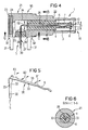
- the embodiment shown in Fig. 4 for an angle connector WS has a conductive housing 21 attached to its Front 22 in the outer conductor 3 of the socket plug part 1 transforms.
- the resilient plug socket of the socket plug part 1 consists of an insulating tube 7 with a S-shaped curved leaf spring 6 on the sides the female connector part 1, the free end of the one-piece Inner conductor 5 is.
- the inner conductor 5 is over its entire The length is in the form of a band, which means that it is a stamped sheet metal part
- the insulating material tube 7 is a finger-like tube attachment of the insulating body 4, the inner tube diameter D2 is equal to the inner diameter D1 of the insulating tube 7.
- the insulating body 4 including the insulating tube 7 is in the extension of the socket plug part 1 in the housing 21 arranged.
- the housing 21 has a cover on its rear 24 closable opening 25 for the assembly of the angled, a horizontal angle arm 26 and a vertical one Angled arm 27 having inner conductor 5.
- the inner conductor 5 is in the region of its horizontal angle arm 26 in the insulating body 4 and in the area of its vertical angle arm 27 held in an additional insulating support 28.
- the Insulating material support 28 is on the underside 29 of the Housing 21, which directly adjoins the rear side 23 thereof, inserted into the housing 21.
- At its free end is the vertical angle arm 27 of the inner conductor 5 as a pin-shaped Soldering foot 30 designed.
- the underside 29 has on the edge side their circumference evenly distributed four pin-shaped solder feet 31, which are each provided with an offset 32.
- the cross-sectional width B1 the curved leaf spring 6, which is the free end of the horizontal Angular arm 26 of the inner conductor 5 is approximately two thirds of the inner diameter D1 of the insulating tube 7.
- the section of the horizontal angle arm 26 of the inner conductor 5, which is located inside the insulating body 4, is B2 in its cross-sectional width at its pipe inside diameter D2 adjusted and points opposite to each other Pages each have a locking hook 33. With With the help of this locking hook 33 is the inner conductor 5, as well the section shown in Fig. 6 and shown in Fig. 4 AA clarifies with its horizontal angle arm 26 in the insulating body 4 fixed or anchored.
- this line section 34 In the transition area between the horizontal angle arm 26 of the Inner conductor 5 and its vertical angle arm 27 forms the Inner conductor 5 together with the housing 21 an insulating material-free Line section 34.
- this line section 34 to the other coaxial line sections of the angled connector WS has the inner conductor 5 an enlarged cross-sectional width in the transition area mentioned B3.
- For fixing or anchoring the inner conductor 5 with its vertical angle arm 27 in the insulating support 28 has the vertical angle arm 27 in the area this insulating material support 28 also on opposite one another Pages each have a locking hook 33.
- the insulating material support 23 shown in FIG. 8 also has their rectangular center channel 35 for the engagement of the inner conductor 5 with its vertical angle arm 27 on its circumference Pointed outer webs 36 parallel to the axis.
- the outer webs 36 are the insulating material support 23, like the one in FIG. 7 shown in Fig. 4 section CC still recognize lets, in the associated opening in the bottom 29th of the housing 21 held in the press fit.
- the embodiment shown in Fig. 9 in longitudinal section for a straight connector GS differs from Angle plug WS in Fig. 4 actually only in that the Bottom side 37 of its housing 38 here its front side 39 is opposite.
- the band-shaped inner conductor 5 is here, apart from the S-shaped curved spring 6, on his a free end on the part of the female connector part 1, a straight inner conductor 5, whose other free end, that emerges from the housing 38 on the underside 37, and parallel to the solder feet on the housing side 31 with offset 32, also a pin-shaped solder foot 30 is.
- the inner conductor 5 of the straight plug shown in FIG. 10 GS in FIG. 9 has the same extension as the inner conductor 5 corresponding to FIGS. 4 and 5 several sections different Section width.
- the one through the S-shaped curved band spring 6 given section again has the Cross-sectional width B1 and that within the insulating body 4 running section again the cross-sectional width B2 attached to the inner tube diameter D2 of the insulating body 4 is adjusted.
- the housing 38 also takes the insulating body here 4 including its insulating tube 7 with the band-shaped inner conductor 5 held here Formation of a non-insulating line section 40 in itself which adjoins the underside 37 of the housing 38.
- the inner conductor 5 has wave impedance matching this line section 40 to the rest coaxial line sections an enlarged cross-sectional width B3.
- the pipe inside diameter is D2 of the insulating body 4 is equal to the inner diameter D1 of the Insulating tube 7.
- the cross-sectional width B1 of the S-shaped band spring 6 of the inner conductor 5, which, as already stated, is approximately two thirds of the value of the inner diameter D1 of the insulating tube 7, is due to the fact that the insulating tube 7 when making the plug connection still the plug pin 11 of the mating connector while ensuring adequate Wave resistance adjustment must take in itself.
- the plug can be an angled plug WS according to FIG. 4 or a straight connector GS according to FIG. 9.
Landscapes
- Coupling Device And Connection With Printed Circuit (AREA)
- Cable Accessories (AREA)
Description
- Fig. 1
- das Buchsen-Steckerteil eines Steckers im Schnitt,
- Fig. 2
- das Buchsen-Steckerteil des Steckers und das Stift-Steckerteil des Gegensteckers im miteinander verbundenen Zustand von Stecker und Gegenstecker im Schnitt,
- Fig. 3
- der Schnitt AA der in Fig. 2 dargestellten Steckverbindung.
- Fig. 4
- ein einen Winkelstecker darstellendes Ausführungsbeispiel im Längsschnitt,
- Fig. 5
- der Innenleiter des Winkelsteckers nach Fig. 4 in perspektivischer Darstellung,
- Fig. 6
- der in Fig. 4 angegebene Schnitt AA des Winkel-Steckers,
- Fig. 7
- der in Fig. 4 angegebene Schnitt BB des Winkel-Steckers,
- Fig. 8
- das den abgewinkelten Teil des Innenleiters im Gehäuse des Winkelsteckers nach Fig. 4 halternde Isolierstoffteil,
- Fig. 9
- ein einen geraden Stecker darstellendes Ausführungsbeispiel im Längsschnitt,
- Fig. 10
- der Innenleiter des geraden Steckers nach Fig. 9 in perspektivischer Darstellung,
| Innendurchmesser Außenleiter Buchsen-Steckerteil | Dib ~ 3.0 |
| Innendurchmesser Außenleiter Stift-Steckerteil | Dis ~ 2.3 |
| Durchmesser Steckerstift | Ds ~ 0,52 |
| Querschnittsbreite Blattfeder: | Qb ~ 0,5 |
| Querschnittshöhe Blattfeder: | Qh ~ 0,2 |
Claims (15)
- Koaxial-Steckverbinder, bestehend aus einem Stecker (WS, GS)mit einem frontseitigen Buchsen-Steckerteil (1) und einem Gegenstecker mit einem frontseitigen Stift-Steckerteil (2),dadurch gekennzeichnet, daßbei dem beim Stecker (WS, GS) und Gegenstecker der Innenleiter (5, 12) im Außenleiter (3, 13) in einem Isolierstoffkörper (4, 14) gehaltert ist undbei dem im vereinigten Zustand des Buchsen-Steckerteils (1) des Steckers (WS, GS) mit dem Stift-Steckerteil (2) des Gegensteckers deren freien Innenleiterenden einerseits und deren freien Außenleiterenden andererseits jeweils unter Federspannung kontaktgebend miteinander verbunden sind,
wenigstens der Teil des Innenleiters (5) des Steckers (WS, GS)im Bereich seines Buchsen-Steckerteils (1) eine innerhalb eines zum Außenleiter (3) konzentrisch ausgerichteten Isolierstoffrohres (7) angeordnete Blattfeder (6) ist, die gemeinsam mit dem Isolierstoffrohr (7) dessen federnde Steckerbuchse darstellt,
das Isolierstoffrohr (7) ein in das Buchsen-Steckerteil (1) des Steckers hineinragender fingerartiger Rohransatz des Isolierstoffkörpers (4) ist,
die Blattfeder (6) über ihre Länge senkrecht zu ihrer Blattfederebene ein-, zwei- oder mehrfach gekrümmt ist und
beim Zusammenfügen von Stecker (WS, GS) und Gegenstecker der Steckerstift (11) beim Eingreifen in die Rohröffnung (9) am freien Ende des Isolierstoffrohres (7) die Blattfeder (6) unter Ausnutzung ihrer gekrümmten Gestaltung gegen die nahe Wandung des Isolierstoffrohres (7) drückt und diese dabei kontaktgebend spannt. - Koaxial-Steckverbinder nach Anspruch 1,
dadurch gekennzeichnet, daß
die Rohröffnung (9) am freien Ende des Isolierstoffrohrs (7) erweitert ist, und zwar zu einem Vorzentriertrichter (10) für den Steckerstift (11) des Gegensteckers. - Koaxial-Steckverbinder nach Anspruch 1 oder 2,
dadurch gekennzeichnet, daß
die Blattfeder (6) mit ihrem freien Ende über den Vorzentriertrichter (10) des Isolierrohres (7) hinaus unter einem solchen Winkel (a) zur Rohrachse (RA) des Isolierstoffrohres (7) nach außen übersteht, daß sie dem Steckerstift (11) beim Zusammenfügen von Stecker und Gegenstecker für ihr Spannen gegen die Innenwandung des Isolierstoffrohres (7) an diesem ihrem freien Ende eine schräge Kontaktzunge (20) bietet, die den Steckvorgang leicht und sicher gestaltet. - Koaxial-Steckverbinder nach einem der vorhergehenden Ansprüche,
dadurch gekennzeichnet, daß
die Blattfeder (6) an ihrem freien Ende eine leicht S-förmige Krümmung mit zwei Krümmungsschwerpunkten (18, 19) aufweist, deren Länge in erster Näherung gleich der Stecktiefe (s) des Steckerstiftes (11) im Isolierstoffrohr (7) im zusammengefügten Zustand von Stecker und Gegenstecker ist. - Koaxial-Steckverbinder nach Anspruch 4,
dadurch gekennzeichnet, daß
der Abstand (a) zwischen den beiden Krümmungsschwerpunkten (18, 19) der leicht S-förmigen Krümmung der Blattfeder (6) an ihrem freien Ende in erster Näherung gleich der halben Stecktiefe (s) des Steckerstiftes (11) im Isolierstoffrohr (7) im zusammengefügten Zustand von Stecker und Gegenstecker ist und
der vom freien Ende der Blattfeder (6) aus erste Krümmungsschwerpunkt (18) der Blattfeder (6) sich innerhalb des Isolierstoffrohres (7) etwas unterhalb des Vorzentriertrichters (10) befindet. - Koaxial-Steckverbinder nach einem der vorhergehenden Ansprüche,
dadurch gekennzeichnet, daß
der Innendurchmesser (di) des Isolierstoffrohres (7) des Steckers in erster Näherung gleich dem zweifachen Durchmesser (Ds) des Steckerstifts (11) des Gegensteckers ist,
die Querschnittsbreite (Qb) der Blattfeder (6) in erster Näherung gleich dem 1,5-fachen des Innendurchmessers (di) des Isolierstoffrohres (7) des Steckers ist und
das Verhältnis von Querschnittsbreite (Qb) zu Querschnittshöhe (Qh) der Blattfeder (6) in erster Näherung 2,5 beträgt. - Koaxial-Steckverbinder nach einem der vorhergehenden Ansprüche,
dadurch gekennzeichnet, daß
das Isolierstoffrohr (7) des Steckers an seinem freien Ende mit einem Ringflansch (8) versehen ist. - Koaxial-Steckverbinder nach einem der vorhergehenden Ansprüche,
gekennzeichnet durch
seine Bemessung für einen Wellenwiderstand von 75 O unter Einhaltung der Dimensionierung entsprechend Normung nach CECC 22230 für "RADIO FREQUENCY COAXIAL CONNECTORS Series 1,0/2,3" bzw. CECC 22241 "RADIO FREQUENCY COAXIAL CONNECTORS Series 1,6 /5,6". - Koaxial-Steckverbinder nach einem der Ansprüche 1 bis 8,
dadurch gekennzeichnet, daß
bei Gestaltung des Steckers (WS, GS) für einen festen Anbau an eine Leiterplatte dessen Gehäuse (21, 38) an seiner Frontseite (22, 39) das Buchsen-Steckerteil (1) und an seiner Unterseite (29, 37) stiftförmige Lötfüße (30, 31) für den Eingriff in diesen leiterplattenseitig zugeordnete kontaktierte Montagelöcher aufweist,
der einstückig ausgeführte Innenleiter (5) über seine gesamte Länge zwischen seinem eine Blattfeder (6) darstellenden einen freien Ende auf seiten des Buchsen-Steckerteils (1) und seinem einen stiftförmigen Lötfuß (30) darstellenden anderen freien Ende, das an der Unterseite (29, 37) aus dem Gehäuse (21, 38) des Steckers (WS, GS) herausragt, bandförmig ausgeführt ist und
der bandförmige Innenleiters (5) in dem Bereich, in dem er sich innerhalb des ihn im Außenleiter (3) halternden Isolierstoffkörpers (4) befindet, und zwar abgesehen von dessen das Isolierstoffrohr (7) darstellenden fingerartigen Rohransatz, in seiner Querschnittsbreite (B2) an dessen Rohr-Innendurchmesser (D2) angepaßt ist und zu seiner Verankerung im Isolierstoffkörper (4) seitliche Sperrhaken (33) aufweist. - Koaxial-Steckverbinder nach Anspruch 9,
gekennzeichnet durch
seine Ausführung als Winkelstecker (WS), mit einem leitenden Gehäuse (21), dessen Innenraum Außenleiterfunktion für den Koaxialleiter hat,
bei dem das Gehäuse (21) an seiner Rückseite (23), die seiner Frontseite (22) gegenüber liegt, eine von einer Abdekkung (24) verschließbare Öffnung (25) für die Montage des abgewinkelten bandförmigen Innenleiters (5) aufweist,
bei dem die an die Rückseite (23) unmittelbar angrenzende Unterseite (29) des Gehäuses (21) mit vier stiftförmigen Lötfüßen (31) versehen ist, die jeweils einen Offset (32) aufweisen und
bei dem der abgewinkelte bandförmige Innenleiter (5) auf seiten seines freien, den stiftförmigen Lötfuß (30) aufweisenden Endes innerhalb des Gehäuses (21) an der Unterseite (29) zusätzlich in einer Isolierstoffstütze (28) gehaltert und hierin mittels seitlicher Sperrhaken (33) verankert ist. - Koaxial-Steckverbinder nach Anspruch 10,
dadurch gekennzeichnet, daß
der im Gehäuse (21) innerhalb des Isolierstoffkörpers (4) einschließlich seines Isolierstoffrohres (7) und der Isolierstoffstütze (28) gehalterte abgewinkelte bandförmige Innenleiter (5) im Winkelbereich des so realisierten Koaxialleiters einen isolierstoffreien Leitungsabschnitt (34) bildet und
der bandförmige Innenleiter (5) zur Wellenwiderstandsanpassung in diesem isolierstoffreien Leitungsabschnitt (34) eine vergrößerte Querschnittsbreite (B3) hat. - Koaxial-Steckverbinder nach Anspruch 9,
gekennzeichnet durch
seine Ausführung als gerader Stecker (GS) mit einem einstückigen leitenden Gehäuse (38), dessen Innenraum Außenleiterfunktion für den Koaxialleiter hat,
bei dem das Gehäuse (38) an seiner Frontseite (39) in den Außenleiter (3) des Buchsen-Steckerteils (1) übergeht und an seiner Unterseite (37), die seiner Frontseite (39) gegenüberliegt, mit vier stiftförmigen Lötfüßen (31) versehen ist, die jeweils einen Offset (32) aufweisen. - Koaxial-Steckverbinder nach Anspruch 12,
dadurch gekennzeichnet, daß
das Gehäuse (38) den Isolierstoffkörper (4) einschließlich seines Isolierstoffrohres (7) mit dem hierin gehalterten bandförmigen Innenleiter (5) unter Bildung eines isolierstoffreien Leitungsabschnitts (40) in sich aufnimmt, der hierbei an die Unterseite (37) des Gehäuses (38) angrenzt und
der bandförmige Innenleiter (5) zur Wellenwiderstandsanpassung im Bereich dieses isolierstoffreien Leitungsabschnitts (40) eine vergrößerte Querschnittsbreite (B3) hat. - Koaxial-Steckverbinder nach einem der vorhergehenden Ansprüche,
dadurch gekennzeichnet, daß
der bandförmige Innenleiter (5) an seinem eine gekrümmte Blattfeder (6) darstellenden freien Ende auf seiten des Buchsen-Steckerteils (1) mit einer Oberflächenveredelung, z.B. in Form einer Goldauflage, versehen ist. - Koaxial-Steckverbinder nach einem der vorhergehenden Ansprüche,
dadurch gekennzeichnet, daß
der Innendurchmesser (D1, di) des einen fingerartigen Rohransatz des Isolierstoffkörpers (4) darstellenden Isolierstoffrohres (7) und der Rohr-Innendurchmesser (D2) des Isolierstoffkörpers (4) gleich groß sind.
Applications Claiming Priority (4)
| Application Number | Priority Date | Filing Date | Title |
|---|---|---|---|
| DE19810799 | 1998-03-12 | ||
| DE19810799 | 1998-03-12 | ||
| DE19815627 | 1998-04-07 | ||
| DE19815627 | 1998-04-07 |
Publications (3)
| Publication Number | Publication Date |
|---|---|
| EP0942496A2 EP0942496A2 (de) | 1999-09-15 |
| EP0942496A3 EP0942496A3 (de) | 2001-08-01 |
| EP0942496B1 true EP0942496B1 (de) | 2004-06-16 |
Family
ID=26044581
Family Applications (1)
| Application Number | Title | Priority Date | Filing Date |
|---|---|---|---|
| EP99104965A Expired - Lifetime EP0942496B1 (de) | 1998-03-12 | 1999-03-12 | Koaxial-Steckverbinder |
Country Status (3)
| Country | Link |
|---|---|
| EP (1) | EP0942496B1 (de) |
| AT (1) | ATE269593T1 (de) |
| DE (1) | DE59909711D1 (de) |
Family Cites Families (5)
| Publication number | Priority date | Publication date | Assignee | Title |
|---|---|---|---|---|
| DE3341356A1 (de) * | 1983-11-15 | 1985-05-23 | Kathrein-Werke Kg, 8200 Rosenheim | Koaxialkabel-anschlussvorrichtung |
| JPH0436065Y2 (de) * | 1984-12-30 | 1992-08-26 | ||
| JPH0231735Y2 (de) * | 1987-02-12 | 1990-08-28 | ||
| US5267871A (en) * | 1992-07-02 | 1993-12-07 | The Whitaker Corporation | Switching electrical connector |
| US5413502A (en) * | 1994-02-01 | 1995-05-09 | Wang; Tsan-Chi | Auto termination type electrical connector |
-
1999
- 1999-03-12 DE DE59909711T patent/DE59909711D1/de not_active Expired - Fee Related
- 1999-03-12 AT AT99104965T patent/ATE269593T1/de not_active IP Right Cessation
- 1999-03-12 EP EP99104965A patent/EP0942496B1/de not_active Expired - Lifetime
Also Published As
| Publication number | Publication date |
|---|---|
| DE59909711D1 (de) | 2004-07-22 |
| EP0942496A3 (de) | 2001-08-01 |
| ATE269593T1 (de) | 2004-07-15 |
| EP0942496A2 (de) | 1999-09-15 |
Similar Documents
| Publication | Publication Date | Title |
|---|---|---|
| DE69421798T2 (de) | Verbinder vom Typ Modular Jack | |
| DE69826608T2 (de) | Koax-Verbinder | |
| DE602005004750T2 (de) | Koaxialer integrierter Verbinder für Leiterplatten- Verbindung | |
| DE69230497T2 (de) | Befestigungsvorrichtung für ein verbindergehäuse | |
| DE69129580T2 (de) | Abgeschirmter elektrischer Verbinder für gedruckte Schaltungsplatten | |
| DE69424850T2 (de) | Elektrischer Verbinder zur Verwendung als Kupplung zweier gedruckter Leiterplatten | |
| DE3784922T2 (de) | Einpressgefertigter flachbausteckverbinder. | |
| DE69311185T2 (de) | Verbinder | |
| DE60031730T2 (de) | Kabelverbinder mit gesteuerter Impedanz | |
| DE69307620T2 (de) | Koaxialer Verbinder für die Verbindung von zwei Leiterplatten | |
| DE69207279T3 (de) | Koaxialverbinder zum Verbinden eines Koaxialkabels mit einer elektronischen gedruckten Schaltung | |
| DE60104328T2 (de) | Koaxialer verbinder | |
| DE2404669A1 (de) | Elektrischer stecker | |
| DE69401272T2 (de) | Verbesserung für die zusammenbaueinrichtung von komponente | |
| DE19751970A1 (de) | Flacher elektrischer Verbinder | |
| DE112018007963B4 (de) | Koaxialverbindervorrichtung | |
| DE69525138T2 (de) | Zuerst Polkontakte zuletzt Erdkontakt unterbrechender Steckverbinder | |
| DE69602020T2 (de) | Zusammenbau einer elektrischenanschlussbuchse und federkontakt dafür | |
| DE69500379T2 (de) | Elektrischer Verbinder mit mehreren Leitern ohne elektromagnetische Abschirmung zwischen den Leitern | |
| EP0867978A2 (de) | Koaxialer Winkelsteckverbinder | |
| DE69803920T2 (de) | Koaxialverbinder für gedruckte schaltungen | |
| EP0924809B1 (de) | HF-Koaxial-Winkel-Steckverbinderteil | |
| DE202008011394U1 (de) | Verbinder | |
| DE69813640T2 (de) | Elektrische verbinder | |
| CH705538A1 (de) | Steckverbindungsteil. |
Legal Events
| Date | Code | Title | Description |
|---|---|---|---|
| PUAI | Public reference made under article 153(3) epc to a published international application that has entered the european phase |
Free format text: ORIGINAL CODE: 0009012 |
|
| AK | Designated contracting states |
Kind code of ref document: A2 Designated state(s): AT BE CH DE FR GB IT LI NL SE |
|
| AX | Request for extension of the european patent |
Free format text: AL;LT;LV;MK;RO;SI |
|
| PUAL | Search report despatched |
Free format text: ORIGINAL CODE: 0009013 |
|
| AK | Designated contracting states |
Kind code of ref document: A3 Designated state(s): AT BE CH CY DE DK ES FI FR GB GR IE IT LI LU MC NL PT SE |
|
| AX | Request for extension of the european patent |
Free format text: AL;LT;LV;MK;RO;SI |
|
| RAP1 | Party data changed (applicant data changed or rights of an application transferred) |
Owner name: TYCO ELECTRONICS LOGISTICS AG |
|
| 17P | Request for examination filed |
Effective date: 20020121 |
|
| AKX | Designation fees paid |
Free format text: AT BE CH DE DK ES FI FR GB LI |
|
| RBV | Designated contracting states (corrected) |
Designated state(s): AT BE CH DE FR GB IT LI NL SE |
|
| 17Q | First examination report despatched |
Effective date: 20030627 |
|
| GRAP | Despatch of communication of intention to grant a patent |
Free format text: ORIGINAL CODE: EPIDOSNIGR1 |
|
| RIC1 | Information provided on ipc code assigned before grant |
Ipc: 7H 01R 13/646 A |
|
| RIC1 | Information provided on ipc code assigned before grant |
Ipc: 7H 01R 13/646 A |
|
| GRAS | Grant fee paid |
Free format text: ORIGINAL CODE: EPIDOSNIGR3 |
|
| GRAA | (expected) grant |
Free format text: ORIGINAL CODE: 0009210 |
|
| AK | Designated contracting states |
Kind code of ref document: B1 Designated state(s): AT BE CH DE FR GB IT LI NL SE |
|
| PG25 | Lapsed in a contracting state [announced via postgrant information from national office to epo] |
Ref country code: NL Free format text: LAPSE BECAUSE OF FAILURE TO SUBMIT A TRANSLATION OF THE DESCRIPTION OR TO PAY THE FEE WITHIN THE PRESCRIBED TIME-LIMIT Effective date: 20040616 Ref country code: FR Free format text: LAPSE BECAUSE OF NON-PAYMENT OF DUE FEES Effective date: 20040616 |
|
| REG | Reference to a national code |
Ref country code: GB Ref legal event code: FG4D Free format text: NOT ENGLISH |
|
| REG | Reference to a national code |
Ref country code: CH Ref legal event code: EP |
|
| REG | Reference to a national code |
Ref country code: CH Ref legal event code: NV Representative=s name: RITSCHER & PARTNER AG |
|
| REF | Corresponds to: |
Ref document number: 59909711 Country of ref document: DE Date of ref document: 20040722 Kind code of ref document: P |
|
| PG25 | Lapsed in a contracting state [announced via postgrant information from national office to epo] |
Ref country code: SE Free format text: LAPSE BECAUSE OF FAILURE TO SUBMIT A TRANSLATION OF THE DESCRIPTION OR TO PAY THE FEE WITHIN THE PRESCRIBED TIME-LIMIT Effective date: 20040916 |
|
| GBT | Gb: translation of ep patent filed (gb section 77(6)(a)/1977) |
Effective date: 20040922 |
|
| NLV1 | Nl: lapsed or annulled due to failure to fulfill the requirements of art. 29p and 29m of the patents act | ||
| PG25 | Lapsed in a contracting state [announced via postgrant information from national office to epo] |
Ref country code: AT Free format text: LAPSE BECAUSE OF NON-PAYMENT OF DUE FEES Effective date: 20050312 |
|
| PGFP | Annual fee paid to national office [announced via postgrant information from national office to epo] |
Ref country code: CH Payment date: 20050321 Year of fee payment: 7 |
|
| PG25 | Lapsed in a contracting state [announced via postgrant information from national office to epo] |
Ref country code: BE Free format text: LAPSE BECAUSE OF NON-PAYMENT OF DUE FEES Effective date: 20050331 |
|
| PLBE | No opposition filed within time limit |
Free format text: ORIGINAL CODE: 0009261 |
|
| STAA | Information on the status of an ep patent application or granted ep patent |
Free format text: STATUS: NO OPPOSITION FILED WITHIN TIME LIMIT |
|
| 26N | No opposition filed |
Effective date: 20050317 |
|
| EN | Fr: translation not filed | ||
| BERE | Be: lapsed |
Owner name: *TYCO ELECTRONICS LOGISTICS A.G. Effective date: 20050331 |
|
| PG25 | Lapsed in a contracting state [announced via postgrant information from national office to epo] |
Ref country code: LI Free format text: LAPSE BECAUSE OF NON-PAYMENT OF DUE FEES Effective date: 20060331 Ref country code: CH Free format text: LAPSE BECAUSE OF NON-PAYMENT OF DUE FEES Effective date: 20060331 |
|
| REG | Reference to a national code |
Ref country code: CH Ref legal event code: PL |
|
| BERE | Be: lapsed |
Owner name: *TYCO ELECTRONICS LOGISTICS A.G. Effective date: 20050331 |
|
| PGFP | Annual fee paid to national office [announced via postgrant information from national office to epo] |
Ref country code: IT Payment date: 20090330 Year of fee payment: 11 Ref country code: DE Payment date: 20090327 Year of fee payment: 11 |
|
| PGFP | Annual fee paid to national office [announced via postgrant information from national office to epo] |
Ref country code: GB Payment date: 20090403 Year of fee payment: 11 |
|
| GBPC | Gb: european patent ceased through non-payment of renewal fee |
Effective date: 20100312 |
|
| PG25 | Lapsed in a contracting state [announced via postgrant information from national office to epo] |
Ref country code: DE Free format text: LAPSE BECAUSE OF NON-PAYMENT OF DUE FEES Effective date: 20101001 |
|
| PG25 | Lapsed in a contracting state [announced via postgrant information from national office to epo] |
Ref country code: GB Free format text: LAPSE BECAUSE OF NON-PAYMENT OF DUE FEES Effective date: 20100312 Ref country code: IT Free format text: LAPSE BECAUSE OF NON-PAYMENT OF DUE FEES Effective date: 20100312 |