EP0942511A2 - Dauermagnetläufer und Montageverfahren - Google Patents
Dauermagnetläufer und Montageverfahren Download PDFInfo
- Publication number
- EP0942511A2 EP0942511A2 EP99104835A EP99104835A EP0942511A2 EP 0942511 A2 EP0942511 A2 EP 0942511A2 EP 99104835 A EP99104835 A EP 99104835A EP 99104835 A EP99104835 A EP 99104835A EP 0942511 A2 EP0942511 A2 EP 0942511A2
- Authority
- EP
- European Patent Office
- Prior art keywords
- core member
- magnetic elements
- curvature
- retaining shell
- permanent magnet
- Prior art date
- Legal status (The legal status is an assumption and is not a legal conclusion. Google has not performed a legal analysis and makes no representation as to the accuracy of the status listed.)
- Withdrawn
Links
Images

Classifications
-
- H—ELECTRICITY
- H02—GENERATION; CONVERSION OR DISTRIBUTION OF ELECTRIC POWER
- H02K—DYNAMO-ELECTRIC MACHINES
- H02K1/00—Details of the magnetic circuit
- H02K1/06—Details of the magnetic circuit characterised by the shape, form or construction
- H02K1/22—Rotating parts of the magnetic circuit
- H02K1/27—Rotor cores with permanent magnets
- H02K1/2706—Inner rotors
- H02K1/272—Inner rotors the magnetisation axis of the magnets being perpendicular to the rotor axis
- H02K1/274—Inner rotors the magnetisation axis of the magnets being perpendicular to the rotor axis the rotor consisting of two or more circumferentially positioned magnets
- H02K1/2753—Inner rotors the magnetisation axis of the magnets being perpendicular to the rotor axis the rotor consisting of two or more circumferentially positioned magnets the rotor consisting of magnets or groups of magnets arranged with alternating polarity
- H02K1/278—Surface mounted magnets; Inset magnets
-
- H—ELECTRICITY
- H02—GENERATION; CONVERSION OR DISTRIBUTION OF ELECTRIC POWER
- H02K—DYNAMO-ELECTRIC MACHINES
- H02K15/00—Processes or apparatus specially adapted for manufacturing, assembling, maintaining or repairing of dynamo-electric machines
- H02K15/02—Processes or apparatus specially adapted for manufacturing, assembling, maintaining or repairing of dynamo-electric machines of stator or rotor bodies
- H02K15/03—Processes or apparatus specially adapted for manufacturing, assembling, maintaining or repairing of dynamo-electric machines of stator or rotor bodies having permanent magnets
-
- Y—GENERAL TAGGING OF NEW TECHNOLOGICAL DEVELOPMENTS; GENERAL TAGGING OF CROSS-SECTIONAL TECHNOLOGIES SPANNING OVER SEVERAL SECTIONS OF THE IPC; TECHNICAL SUBJECTS COVERED BY FORMER USPC CROSS-REFERENCE ART COLLECTIONS [XRACs] AND DIGESTS
- Y10—TECHNICAL SUBJECTS COVERED BY FORMER USPC
- Y10T—TECHNICAL SUBJECTS COVERED BY FORMER US CLASSIFICATION
- Y10T29/00—Metal working
- Y10T29/49—Method of mechanical manufacture
- Y10T29/49002—Electrical device making
- Y10T29/49009—Dynamoelectric machine
- Y10T29/49012—Rotor
Definitions
- the present invention relates generally to permanent magnet rotors for electric motors, and more specifically to novel rotors having particular application in electronically commutated motors operable at relatively high rotor speeds, and to a novel method for assembly of the rotor and to electric motors provided with said rotors.
- Permanent magnet rotors for dynamoelectric machines typically are constructed of a generally cylindrical iron core which may be of a solid, laminated or sintered metal construction, and around which are positioned a plurality of magnetic elements.
- the magnetic elements typically are arcuate shaped with an inner contour conforming to the outer surface of the core such that the magnets may contact the outer circumferential surface of the core.
- the magnetic elements generally are made from barium or strontium ferrite, samarium cobalt, neodymium iron boron (rare earth) or other known magnetic materials.
- Permanent magnet rotors of this general type find particular application in motors having control circuitry which controls energization of the windings in one or more predetermined sequences to provide rotational magnetic fields and thereby rotation of the rotor.
- the relative high mass of the materials used to form magnetic elements and the relatively high rotor speeds create significant forces during rotor operation, including centrifugal forces and substantial momentum forces upon sudden stops or reversals of direction of rotor rotation. Retention of the magnetic elements in predetermined radial positions about the core is, therefore, necessary for reliable motor operation.
- motors operating in fluid systems are contained in a hermetically sealed unit with the motor exposed to the fluid, such as the coolant in a refrigeration system.
- a hermetically sealed unit with the motor exposed to the fluid, such as the coolant in a refrigeration system.
- the fluid such as the coolant in a refrigeration system.
- permanent magnet variable speed motors to drive compressors in refrigeration systems.
- adhesives contain organic materials which are soluble in, or are leached out by, the refrigerant fluids used in these systems, resulting in matter being introduced into these fluids or otherwise accumulating in the capillary tubes and thereby causing serious or complete system failure, a motor containing minimum amounts of organic materials is desirable.
- One such technique has been to wrap the magnetic elements with a plastic or fiberglass material, or a relatively fine wire, and then covering the wrapping with an adhesive or epoxy resin overcoat.
- This technique is disadvantageous for its obvious costly labor intensive requirements and also because all of these materials become potential contaminants in any fluid system in which the rotor assembly may be used.
- One of the primary objects of the present invention is to provide a novel permanent magnet rotor assembly in which the magnetic elements are encased in such a manner as to efficiently prevent the accumulation of dust and also to retain within the rotor assembly any particles attracted by the magnetic elements, or any particles of magnetic material that may break off the magnetic elements as a result of handling, chipping, flaking or cracking.
- Another primary object of the present invention is to provide a novel permanent magnet rotor assembly in which the magnetic elements are encased in such as manner as to eliminate the possibility of organic or other material leaking or leaching from the rotor assembly and thereby becoming the source of a contaminant in any fluid system in which the rotor may be used.
- Another primary object of the present invention is to provide a novel permanent magnet rotor assembly which is particularly tolerant of substantial dimensional tolerance variations in the magnetic elements and retaining shell.
- Another primary object of the present invention is to provide a novel method for assembling a permanent magnet rotor which provides relatively low cost and ease of manufacture and yet results in optimum magnetic element retention.
- Another primary object of the present invention is to provide a permanent magnet rotor assembly having improved means to prevent slippage of the magnets relative to the rotor during high speed operation.
- Still another object of the present invention is to provide a rotor structure which is extremely durable and yet relatively easy to manufacture and at relatively low cost.
- a further object of the present invention is to provide an electric motor with a permanent magnet rotor constructed and/or assembled in accordance with the foregoing objects.
- the invention consists in the novel parts, constructions, arrangements, combinations, steps and improvements herein shown and described.
- a permanent magnet rotor comprising a cylindrical rotor core member having a longitudinal axis, first and second flat ends, and an outer circumferentially extending surface having an outer radius of curvature; a substantially cylindrical magnetic member having a longitudinal axis and inner and outer substantially circumferentially extending surfaces, said inner surface having a circumference substantially equal to the outer circumference of said core member; a hollow cylindrical retaining shell having an inner circumference substantially equal to the outer circumference of said magnetic member; means for preventing relative movement between said core member, said magnetic member and said retaining shell; and first and second annular end plates secured to said first and second flat ends of said core member, respectively, said end plates having an outer circumference substantially equal to the inner circumference of said retaining shell.
- a method of assembling a permanent magnet rotor in accordance with the present invention comprises the steps of providing a hollow cylindrical retaining shell having first and second ends, an inner circumference, an inner surface and an inner radius of curvature; coating said inner surface of said retaining shell with an adhesive; providing a plurality of arcuate magnetic elements having inner and outer arcuate surfaces and inner and outer radii of curvature, said outer radius of curvature being substantially equal to said inner radius of curvature of said retaining shell; positioning said magnetic elements within said retaining shell with said outer arcuate surfaces adhered to said inner surface of said retaining shell such that said inner arcuate surfaces of said magnetic elements define a cylindrical space with a diameter; coating said inner arcuate surfaces of said magnetic elements with an adhesive; inserting a cylindrical rotor core member into said cylindrical space, said core member having first and second flat ends, an outer radius of curvature substantially equal to said inner radius of curvature of said magnetic elements, and a cross-sectional diameter substantially equal to said diameter of said cylindrical space; securing
- the method of assembling a permanent magnet rotor in accordance with the present invention comprises the steps of providing a cylindrical rotor core member having a longitudinal axis, first and second flat ends, and an outer circumferentially extending surface having an outer radius of curvature; securing a first annular end plate to said first flat end of said core member, said end plate having an outer circumference; providing a hollow cylindrical retaining shell having first and second ends, and an inner circumferentially extending surface having an inner radius of curvature, the inner circumference of said retaining shell being substantially equal to the outer circumference of said first end plate; sliding said core member and said first end plate into said retaining shell until said first end plate is flush with said first end of said retaining shell, whereupon an annular space is created between said outer surface of said core member and said inner surface of said retaining shell; providing a plurality of arcuate magnetic elements having inner and outer radii of curvature and longitudinally extending opposed radial end surface, said inner radius of curvature of said
- the method of assembling a permanent magnet rotor in accordance with the present invention thus includes the steps of forming a plurality of discrete grooves in the outer peripheral surface of a cylindrical rotor core member, each of said grooves being parallel to each other and to the longitudinal axis of the core; securing a circular end plate to one end of the rotor core member, the end plate having a diameter greater than that of the core member; placing the end plate and core subassembly within a thin-walled hollow cylindrical retaining shell adapted to slip-fit over the outer circumferential edge of the end plate until one end of the retaining shell is flush with the outer face of the end plate; inserting a plurality of arcuate-shaped magnetic elements into the annulus between the core and the retaining shell, each of said magnetic elements having a chamfered edge along its longitudinally extending inner radii; aligning the chamfered edges of adjacent magnetic elements with each of said grooves in the core so as to form a plurality of enclosed longitudinally extending channels between the
- Use of the assembly methods of the present invention facilitates construction of a rotor structure which is highly tolerant of a relatively wide range of dimensional variations in the magnetic elements which surround the core while assuring fixed retention of the magnetic elements relative to the core, both longitudinally and rotationally.
- Rotors produced in accordance with the preferred embodiments of the present invention are completely devoid of organic materials and, therefore, can be used to particular advantage in fluid systems such as, for example, hermetically sealed refrigeration compressor applications, where exposure to refrigeration and/or lubricating fluids is likewise to occur, and where relatively high efficiency ratings may be required.
- a rotor assembly in accordance with the present invention fully encases the magnetic elements in non-magnetic, preferably metallic material, thereby preventing the magnetic elements from attracting dust and also retaining any free particles of magnetic material within the non-magnetic encasement structure.
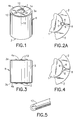
- Fig. 1 is a perspective view of a permanent magnet rotor constructed in accordance with a preferred embodiment of this invention.
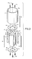
- Fig. 2 is an exploded view of the rotor of Fig. 1.
- Fig. 2A is an enlarged schematic view, partially broken away, illustrating the assembled position of one of the locking spiral pin members shown in Fig. 2.
- Fig. 3 is an elevational view of the rotor of Fig. 1.
- Fig. 4 is an enlarged schematic view similar to Fig. 2A illustrating an alternate configuration for locating the locking spiral pin member shown in Fig. 2A.
- Fig. 5 is a partial perspective view of an alternate embodiment for the locking pin member of Fig. 2A, the view illustrating a "c"-shaped elongated pin structure.
- Fig. 6 is a perspective view of a permanent magnet rotor construction in accordance with an alternate embodiment of the invention.
- Fig. 7 is an exploded view of the rotor of Fig. 6.
- Fig. 8 is an elevational view of the rotor of Fig. 7.
- rotor R includes a rotor core 1 , a pair of annular end plates 4a and 4b , a plurality of arcuate shaped magnetic elements 2 , and an outer magnet retaining shell 3 which, as more fully described hereafter, retains the magnetic elements 2 securely against the core 1 to prevent movement of the magnets relative to the core.
- the core 1 is illustrated as comprising a solid metallic or sintered iron cylindrical core having a longitudinal cylindrical bore 1a extending axially through the core and defining a central axis 10 .
- core 1 may be made as a laminated metallic core, which may be preferred in some applications.
- magnetic elements 2 are employed which comprise similarly shaped arcuate magnetizable elements. It will be understood that the term “magnetic elements” also includes magnetizable elements since, at the time of assembly with core 1 to form the rotor R , the magnetizable elements may or may not be in a magnetized condition.
- Each magnetic element 2 has an inner arcuate surface 2a having a radius of curvature substantially identical to the radius of curvature of the outer cylindrical surface of the core 1 so as to fit closely against the circumferentially extending surface of the core when the rotor R is assembled.
- the end plates 4a and 4b comprise identical flat rings or annular washers, preferably formed from aluminum or, alternatively, non-magnetic stainless steel, having an outer radius preferably equal to the combined radius of the cylindrical surface of core 1 and the outer surface of the magnetic elements 2 when assembled onto the core.
- Each end plate 4a and 4b has an inner radius larger than the radius or bore 1a in core 1 , but smaller than the radius of the outer cylindrical surface of the core.
- the rotor retaining shell 3 is preferably made from a non-magnetic metal, such as stainless steel.
- the wall thickness of shell 3 is preferably in the order of 0.254 mm, but advantageously may range from about 0.13 to about 0.5 mm in thickness.
- Shell 3 has a longitudinal length equal to the longitudinal length of the core 1 plus the combined thickness of the two end plates 4a and 4b , and defines opposite continuous circular end edge surfaces 3a and 3b which lie in planes perpendicular to the longitudinal axis of the shell and flush with the outer flat surfaces of the end plates.
- spring biasing means are provided to prevent relative rotational movement between magnetic elements 2 and rotor core member 1 , and also to urge the magnetic elements into force-fitting contact with the inner surface of retaining shell 3 .
- the outer circumferential surface of core 1 is provided with a plurality of longitudinally extending generally "v"-shaped grooves 5 (equal in number to the number of magnetic elements 2 ), and the inner longitudinally extending radial edges of each magnetic element 2 are chamfered, as shown at 6 , such that when magnets 2 are aligned about core 1 between grooves 5 , the grooves and chamfers mate to form a generally diamond-shaped channel 7 , as best seen in Fig. 2A.
- an appropriately sized elongated spiral pin member 8 is inserted into each channel 7 .
- Pin 8 is preferably formed by rolling or coiling a narrow, thin metallic band of non-magnetic stainless steel, or other suitable material, into an elongated cylindrical configuration, so as to be spring-biased.
- Fig. 4 an alternate embodiment of the present invention is illustrated.
- the outer surface of rotor core 1 remains smooth and spiral spring pins 8 are inserted into each of the triangularly-shaped channels 9 formed by mating chamfered surfaces 6 of magnets 2 and the surface of core 1 .
- the radially outwardly directed spring force, or wedging action of spiral pins 8 holds magnets 2 against both core 1 and retaining shell 3 by means of a tight friction fit.
- FIG. 5 an alternate embodiment of the spring-biasing member of the present invention is illustrated at reference numeral 11.
- an elongatd pin member is provided which is generally "c"-shaped in cross-section.
- Pin 11 is sized such that it must be compressed in order to insert it into either of the channel configurations 7 or 9 and thereafter exerts an outwardly directed spring force or wedging action against the channel walls similarly to that of pins 8 .
- each of the end plates 4a and 4b is assembled to core 1 by means of a plurality, preferably three, of spiral, self-threading drive screws 12 which are driven or force-pressed through smooth-walled holes 13 and 14 bored through the end plates 4a and 4b and into core 1, respectively ( Fig. 2 ).
- screws 12 Upon being briven or pressed into holes 13 and 14, screws 12 create threads in the walls of the boreholes and thereby lock end plates 4a and 4b against the ends of core 1 .
- it will be understood that equally satisfactory results may be obtained by forming threads in holes 13 and 14 and utilizing appropriate machine screws to mount the end plates in place.
- end plates 4a and 4b are formed from steel, no bore holes or screws are required to secure the end plates to core 1 . Instead, each of the end plates 4a and 4b is assembled to core 1 by laser welding.
- FIG. 6-8 there is illustrated an alternate embodiment of the present invention, indicated generally at R'.
- the core 1 , magnetic elements 2', retaining shell 3 and end plates 4'a and 4'b are all held together with a suitable curable adhesive or cement bonding material to provide a hermetically sealed encasement of the magnets.
- magnets 2' differ from magnets 2 only in that no chamfered edges are required and end plates 4'a and 4'b differ from end plates 4a and 4b only in that no bore holes are required.
- the retaining shell 3 also serves as the assembly fixture for building the rotor assembly.
- the retaining shell 3 is first coated with a suitable adhesive on its inner surface, whereupon the magnetic elements 2' are positioned as desired within the shell 3 with their outer arcuate surfaces adhered to the inner surface of the retaining shell 3 .
- the inner arcuate surfaces 2'a of the magnetic elements 2' are then adhesively coated, whereupon the rotor core 1 is slip-fit into the cylindrical hole formed by the inner arcuate surfaces 2'a of the magnetic elements 2' and thereafter adhered to the inner cylindrical magnet wall.
- each of the end plates 4'a and 4'b is, in turn, coated with a suitable adhesive and slip-fit within the retaining shell 3 at each end thereof and adhered to opposite ends of the core whereupon the outside faces of the end plates 4'a and 4'b advantageously are flush with the respective outer circumferential edges of the retaining shell 3 .
- the entire core/magnet/shell assembly is suitably clamped to hold the components in place until the adhesive is cured.
- the aforedescribed alternate embodiment of the rotor assembly of the present invention provides an effective seal of the ferric and ferromagnetic materials of the rotor at a relatively low manufacturing cost.
- the retaining shell 3 is not deformed or press-fit about the magnet/core subassembly but, instead, each of the components of the core/magnet/shell assembly merely fits within one another in line-to-line relationship and are held in place by the respective layers of adhesive or cement bonding material.
- the ends of shell 3 are not crimped or otherwise rolled over onto the end plates but, instead, remain flush with the outside faces of end plates 4'a and 4'b.
- the aforedescribed adhesive sealed rotor structure advantageously is useful in systems where the motor is not exposed to fluids which are capable of dissolving or leaching the adhesive or other bonding material.
- grooves 5 , channels 7 and 9 and pins 8 and 11 are merely representative of many configurations that could be employed and yet perform the described function with equally satisfactory results.
- grooves 5 and channels 7 and 9 may have rectangular, rounded or "u"-shaped configurations, or combinations thereof.
- pins 8 and 11 may be of any other appropriate shape or construction, so long as they perform the described spring-biasing and locking functions.
- any suitable number of arcuate magnetic elements 2 and 2' may be provided and each element may have other configurations, such as the shape of a bread loaf, i.e., where both the inner and outer radial surfaces are arcuate shaped but with a somewhat greater distance therebetween than is shown in Figs. 2 and 7 .
- the magnetic elements also advantageously may be formed as a single unitary annular structure and magnetized as desired at various radial positions about the magnetic ring element. If so constructed, suitably shaped grooves will then be formed on the inner annular surface of the magnetic ring so as to mate with grooves 5 on the core surface to thereby form channels such as shown at 7 .
Landscapes
- Engineering & Computer Science (AREA)
- Power Engineering (AREA)
- Manufacturing & Machinery (AREA)
- Permanent Field Magnets Of Synchronous Machinery (AREA)
Applications Claiming Priority (4)
| Application Number | Priority Date | Filing Date | Title |
|---|---|---|---|
| US7791898P | 1998-03-13 | 1998-03-13 | |
| US77918P | 1998-03-13 | ||
| US251020 | 1999-02-16 | ||
| US09/251,020 US6084330A (en) | 1998-03-13 | 1999-02-16 | Permanent magnet rotor and method of assembly |
Publications (2)
| Publication Number | Publication Date |
|---|---|
| EP0942511A2 true EP0942511A2 (de) | 1999-09-15 |
| EP0942511A3 EP0942511A3 (de) | 2001-07-25 |
Family
ID=26759850
Family Applications (1)
| Application Number | Title | Priority Date | Filing Date |
|---|---|---|---|
| EP99104835A Withdrawn EP0942511A3 (de) | 1998-03-13 | 1999-03-11 | Dauermagnetläufer und Montageverfahren |
Country Status (3)
| Country | Link |
|---|---|
| US (1) | US6084330A (de) |
| EP (1) | EP0942511A3 (de) |
| JP (1) | JPH11318048A (de) |
Cited By (9)
| Publication number | Priority date | Publication date | Assignee | Title |
|---|---|---|---|---|
| EP1152515A3 (de) * | 2000-04-28 | 2003-12-10 | Siemens Aktiengesellschaft | Läufer für hohe Drehzahlen |
| EP1533883A1 (de) * | 2003-11-18 | 2005-05-25 | SISME IMMOBILIARE S.p.A. | Permanentmagnetrotor zum schnellen Zusammenbau für elektrische Motoren und Verfahren zur Herstellung derselben |
| WO2007037738A1 (en) * | 2005-09-28 | 2007-04-05 | Itt Manufacturing Enterprises Inc. | Method for mounting magnet elements on a rotor for use in a permanent magnet motor |
| RU2312445C2 (ru) * | 2005-07-08 | 2007-12-10 | Открытое акционерное общество "Электропривод" | Двухпакетный торцевой генератор |
| US7545067B2 (en) | 2005-07-29 | 2009-06-09 | Siemens Aktiengesellschaft | Permanent magnet rotor for a brushless electrical machine |
| EP1455435B1 (de) * | 2003-03-04 | 2011-09-28 | LG Electronics, Inc. | Einphasiger Asynchronmotor mit einer dauermagnetischen Einheit |
| CN104854782A (zh) * | 2012-12-17 | 2015-08-19 | 大陆汽车有限责任公司 | 燃料泵 |
| EP3264571A3 (de) * | 2016-06-28 | 2018-04-04 | Trane International Inc. | Elektromotor mit abführung von oberwellenenergie |
| CN110544998A (zh) * | 2014-06-13 | 2019-12-06 | Lg 伊诺特有限公司 | 转子组件、马达和双离合器变速器 |
Families Citing this family (33)
| Publication number | Priority date | Publication date | Assignee | Title |
|---|---|---|---|---|
| BR9705306B1 (pt) * | 1997-10-24 | 2010-08-10 | rotor de motor elétrico. | |
| US6836954B1 (en) * | 1998-01-20 | 2005-01-04 | Zanussi Elettromeccanica S.P.A. | Rotor for an electronically commutated motor and improved method for the mass production thereof |
| JP2000197290A (ja) * | 1998-12-25 | 2000-07-14 | Hitachi Ltd | 永久磁石式回転電機及びそれを用いた電動車両 |
| US6963151B2 (en) * | 2002-02-04 | 2005-11-08 | Electric Boat Corporation | Composite lamina arrangement for canning of motors |
| US6974522B2 (en) * | 2003-09-29 | 2005-12-13 | Torrington Research Co. | Method and apparatus for mounting a plurality of magnet segments on a back ring |
| KR100565801B1 (ko) * | 2004-01-20 | 2006-03-29 | 삼성전자주식회사 | 렌즈셔터 구동용 스테핑모터 및 렌즈셔터 구동장치 및이를 가지는 렌즈유닛 |
| JP4475993B2 (ja) * | 2004-03-22 | 2010-06-09 | 並木精密宝石株式会社 | 多機能型振動アクチュエータ及び携帯端末機器 |
| JP4803525B2 (ja) * | 2004-04-12 | 2011-10-26 | 株式会社一宮電機 | ブラシレスモータ用ロータ、及びブラシレスモータ |
| US7183683B2 (en) * | 2005-06-23 | 2007-02-27 | Peopleflo Manufacturing Inc. | Inner magnet of a magnetic coupling |
| US7549205B2 (en) * | 2005-06-24 | 2009-06-23 | Peopleflo Manufacturing Inc. | Assembly and method for pre-stressing a magnetic coupling canister |
| CN100428611C (zh) * | 2005-11-16 | 2008-10-22 | 许晓华 | 直流电机四片装磁钢的夹持装置 |
| US20070138891A1 (en) * | 2005-12-19 | 2007-06-21 | Emerson Electric Co. | Magnet retention and positioning sleeve for surface mounted rotor assemblies |
| WO2007074036A1 (en) | 2005-12-29 | 2007-07-05 | Arcelik Anonim Sirketi | An electric motor |
| US20070177978A1 (en) * | 2006-01-31 | 2007-08-02 | Zhongshan Broad-Ocean Motor Co., Ltd. | Damping structure for a rotor assembly of a motor |
| US7710081B2 (en) | 2006-10-27 | 2010-05-04 | Direct Drive Systems, Inc. | Electromechanical energy conversion systems |
| US20100019598A1 (en) | 2008-07-28 | 2010-01-28 | Direct Drive Systems, Inc. | Rotor for an electric machine |
| KR101070439B1 (ko) * | 2009-10-19 | 2011-10-06 | 영 춘 정 | 영구자석을 이용한 전기모터용 회전자 |
| JP2011120328A (ja) * | 2009-12-01 | 2011-06-16 | Yaskawa Electric Corp | 永久磁石形モータ用のロータ、永久磁石形モータ及びこれらの製造方法 |
| US9479018B1 (en) * | 2011-06-24 | 2016-10-25 | Power Group International Corporation | Electrical machine having locked permanent magnets and rotor slices |
| US9190878B2 (en) | 2012-03-16 | 2015-11-17 | Globe Motors, Inc. | Rotor including anti-rotation feature for multi-pole structure |
| JP2013198233A (ja) * | 2012-03-19 | 2013-09-30 | Hitachi Automotive Systems Ltd | 回転電機 |
| CN103107662B (zh) * | 2012-12-31 | 2015-07-08 | 北京金风科创风电设备有限公司 | 加热装置及采用该加热装置的磁轭和磁体的粘结方法 |
| EP3292614A1 (de) * | 2015-05-06 | 2018-03-14 | Arçelik Anonim Sirketi | Halteanordnung zur verwendung bei einem elektromotor eines hermetischen verdichters |
| DE102017203736A1 (de) | 2017-03-07 | 2018-09-13 | Mahle International Gmbh | Elektromotor |
| DE102017223622A1 (de) * | 2017-12-21 | 2019-06-27 | Brose Fahrzeugteile GmbH & Co. Kommanditgesellschaft, Würzburg | Rotor für einen Elektromotor und Elektromotor |
| EP3767808A4 (de) | 2018-03-16 | 2021-12-15 | Mitsui High-Tec, Inc. | Verfahren zur herstellung eines eisenkernprodukts, eisenkernprodukt und verfahren zur herstellung eines rotors |
| JP6382465B1 (ja) * | 2018-03-16 | 2018-08-29 | 株式会社三井ハイテック | 回転体の製造方法 |
| JP6430058B1 (ja) * | 2018-07-20 | 2018-11-28 | 株式会社三井ハイテック | 回転体の製造方法 |
| EP4037159A1 (de) | 2021-02-02 | 2022-08-03 | Black & Decker, Inc. | Leiterplattenanordnung für einen kompakten bürstenlosen motor |
| CN116388423A (zh) * | 2023-03-15 | 2023-07-04 | 大连环友屏蔽泵有限公司 | 转子、转子的组装方法、转子的检漏方法、屏蔽电泵 |
| WO2025017825A1 (ja) * | 2023-07-18 | 2025-01-23 | 日産自動車株式会社 | ロータ |
| US20260012051A1 (en) * | 2024-07-08 | 2026-01-08 | Schaeffler Technologies AG & Co. KG | Segmented end plates for electric motors |
| TWI907197B (zh) * | 2024-12-05 | 2025-12-01 | 奇鋐科技股份有限公司 | 轉子磁鐵固定結構 |
Family Cites Families (14)
| Publication number | Priority date | Publication date | Assignee | Title |
|---|---|---|---|---|
| JPS589500Y2 (ja) * | 1977-06-24 | 1983-02-21 | 株式会社デンソー | 磁石発電機の回転子 |
| DE3622231A1 (de) * | 1986-07-02 | 1988-01-07 | Bosch Gmbh Robert | Permanentmagnetrotor fuer elektrische maschinen |
| US4742259A (en) * | 1987-05-11 | 1988-05-03 | Franklin Electric Co., Inc. | Permanent magnet rotor for electric motor |
| US5345669A (en) * | 1988-06-08 | 1994-09-13 | General Electric Company | Method of making a permanent magnet rotor |
| US5144735A (en) * | 1988-06-08 | 1992-09-08 | General Electric Company | Apparatus for assembling a permanent magnet rotor |
| US5040286A (en) * | 1988-06-08 | 1991-08-20 | General Electric Company | Method for making permanent magnet rotor |
| US5237737A (en) * | 1988-06-08 | 1993-08-24 | General Electric Company | Method of making a permanent magnet rotor |
| US5563463A (en) * | 1988-06-08 | 1996-10-08 | General Electric Company | Permanent magnet rotor |
| US4973872A (en) * | 1988-10-07 | 1990-11-27 | Emerson Electric Co. | Dynamoelectric machine rotor assembly with improved magnet retention stucture |
| US4910861A (en) * | 1988-10-07 | 1990-03-27 | Emerson Electric Co. | Method of manufacturing retention structure for electric motor rotor magnets |
| US4918802A (en) * | 1989-02-06 | 1990-04-24 | Franklin Electric Co., Inc. | Method and apparatus for making permanent magnet rotors |
| US6348752B1 (en) * | 1992-04-06 | 2002-02-19 | General Electric Company | Integral motor and control |
| JPH06253515A (ja) * | 1993-02-24 | 1994-09-09 | Matsushita Refrig Co Ltd | 自己始動形永久磁石式同期電動機の回転子 |
| US5898990A (en) * | 1997-04-14 | 1999-05-04 | General Motors Corporation | Method of assembling a magnet ring on a rotor |
-
1999
- 1999-02-16 US US09/251,020 patent/US6084330A/en not_active Expired - Fee Related
- 1999-03-11 EP EP99104835A patent/EP0942511A3/de not_active Withdrawn
- 1999-03-15 JP JP11068372A patent/JPH11318048A/ja active Pending
Cited By (10)
| Publication number | Priority date | Publication date | Assignee | Title |
|---|---|---|---|---|
| EP1152515A3 (de) * | 2000-04-28 | 2003-12-10 | Siemens Aktiengesellschaft | Läufer für hohe Drehzahlen |
| EP1455435B1 (de) * | 2003-03-04 | 2011-09-28 | LG Electronics, Inc. | Einphasiger Asynchronmotor mit einer dauermagnetischen Einheit |
| EP1533883A1 (de) * | 2003-11-18 | 2005-05-25 | SISME IMMOBILIARE S.p.A. | Permanentmagnetrotor zum schnellen Zusammenbau für elektrische Motoren und Verfahren zur Herstellung derselben |
| RU2312445C2 (ru) * | 2005-07-08 | 2007-12-10 | Открытое акционерное общество "Электропривод" | Двухпакетный торцевой генератор |
| US7545067B2 (en) | 2005-07-29 | 2009-06-09 | Siemens Aktiengesellschaft | Permanent magnet rotor for a brushless electrical machine |
| WO2007037738A1 (en) * | 2005-09-28 | 2007-04-05 | Itt Manufacturing Enterprises Inc. | Method for mounting magnet elements on a rotor for use in a permanent magnet motor |
| US7761976B2 (en) | 2005-09-28 | 2010-07-27 | Itt Manufacturing Enterprises Inc. | Method for mounting magnet elements on a rotor for use in a permanent magnet motor |
| CN104854782A (zh) * | 2012-12-17 | 2015-08-19 | 大陆汽车有限责任公司 | 燃料泵 |
| CN110544998A (zh) * | 2014-06-13 | 2019-12-06 | Lg 伊诺特有限公司 | 转子组件、马达和双离合器变速器 |
| EP3264571A3 (de) * | 2016-06-28 | 2018-04-04 | Trane International Inc. | Elektromotor mit abführung von oberwellenenergie |
Also Published As
| Publication number | Publication date |
|---|---|
| EP0942511A3 (de) | 2001-07-25 |
| US6084330A (en) | 2000-07-04 |
| JPH11318048A (ja) | 1999-11-16 |
Similar Documents
| Publication | Publication Date | Title |
|---|---|---|
| US6084330A (en) | Permanent magnet rotor and method of assembly | |
| US5345669A (en) | Method of making a permanent magnet rotor | |
| US5237737A (en) | Method of making a permanent magnet rotor | |
| KR100310721B1 (ko) | 무브러시모터의영구자석회전자및그제조방법 | |
| US5779456A (en) | Magnetic drive | |
| US5175461A (en) | Permanent magnet rotor having magnet positioning and retaining means | |
| US5923111A (en) | Modular permanent-magnet electric motor | |
| US5898990A (en) | Method of assembling a magnet ring on a rotor | |
| US4918802A (en) | Method and apparatus for making permanent magnet rotors | |
| JPS58163255A (ja) | 永久磁石式同期モ−タの回転子 | |
| EP1715560A1 (de) | System zur Befestigung von Dauermagneten | |
| US20020195900A1 (en) | Stator with a radial winding and method for manufacturing same | |
| US20130123026A1 (en) | Magnetic drive power transfer system | |
| JPH0583892A (ja) | 永久磁石回転子 | |
| US6289575B1 (en) | Method of manufacturing a stacked stator assembly for a linear motor | |
| US20230052600A1 (en) | Electric machines having a radially embedded permanent magnet rotor and methods thereof | |
| US20050236914A1 (en) | Stepping motor and drive device | |
| JP3770300B2 (ja) | 回転子およびステッピングモータ | |
| US10826341B2 (en) | Rotor of motor apparatus | |
| EP0350789A1 (de) | Elektromagnetische Kupplung | |
| JPH099539A (ja) | 永久磁石回転電機の回転子 | |
| JPH09219946A (ja) | 小型モータ用のロータ | |
| JP3105181B2 (ja) | マグネットカップリングの耐食性インナーマグネット | |
| EP0801455A2 (de) | Zweiphasiger unipolar betriebener bürstenloser Gleichstrommotor | |
| CN218569951U (zh) | 转子、旋转电机以及泵 |
Legal Events
| Date | Code | Title | Description |
|---|---|---|---|
| PUAI | Public reference made under article 153(3) epc to a published international application that has entered the european phase |
Free format text: ORIGINAL CODE: 0009012 |
|
| AK | Designated contracting states |
Kind code of ref document: A2 Designated state(s): CH DE FR GB IT LI SE |
|
| AX | Request for extension of the european patent |
Free format text: AL;LT;LV;MK;RO;SI |
|
| PUAL | Search report despatched |
Free format text: ORIGINAL CODE: 0009013 |
|
| AK | Designated contracting states |
Kind code of ref document: A3 Designated state(s): AT BE CH CY DE DK ES FI FR GB GR IE IT LI LU MC NL PT SE |
|
| AX | Request for extension of the european patent |
Free format text: AL;LT;LV;MK;RO;SI |
|
| AKX | Designation fees paid |
Free format text: CH DE FR GB IT LI SE |
|
| STAA | Information on the status of an ep patent application or granted ep patent |
Free format text: STATUS: THE APPLICATION IS DEEMED TO BE WITHDRAWN |
|
| 18D | Application deemed to be withdrawn |
Effective date: 20020126 |