EP0942541A2 - Système de communication à AMDC avec contrÔle de la puissance de transmission - Google Patents
Système de communication à AMDC avec contrÔle de la puissance de transmission Download PDFInfo
- Publication number
- EP0942541A2 EP0942541A2 EP19990102883 EP99102883A EP0942541A2 EP 0942541 A2 EP0942541 A2 EP 0942541A2 EP 19990102883 EP19990102883 EP 19990102883 EP 99102883 A EP99102883 A EP 99102883A EP 0942541 A2 EP0942541 A2 EP 0942541A2
- Authority
- EP
- European Patent Office
- Prior art keywords
- spreading code
- transmission power
- spreading
- transmission
- communications
- Prior art date
- Legal status (The legal status is an assumption and is not a legal conclusion. Google has not performed a legal analysis and makes no representation as to the accuracy of the status listed.)
- Withdrawn
Links
Images


Classifications
-
- H—ELECTRICITY
- H04—ELECTRIC COMMUNICATION TECHNIQUE
- H04W—WIRELESS COMMUNICATION NETWORKS
- H04W52/00—Power management, e.g. Transmission Power Control [TPC] or power classes
- H04W52/04—Transmission power control [TPC]
- H04W52/18—TPC being performed according to specific parameters
- H04W52/26—TPC being performed according to specific parameters using transmission rate or quality of service QoS [Quality of Service]
- H04W52/267—TPC being performed according to specific parameters using transmission rate or quality of service QoS [Quality of Service] taking into account the information rate
-
- H—ELECTRICITY
- H04—ELECTRIC COMMUNICATION TECHNIQUE
- H04B—TRANSMISSION
- H04B7/00—Radio transmission systems, i.e. using radiation field
- H04B7/24—Radio transmission systems, i.e. using radiation field for communication between two or more posts
- H04B7/26—Radio transmission systems, i.e. using radiation field for communication between two or more posts at least one of which is mobile
-
- H—ELECTRICITY
- H04—ELECTRIC COMMUNICATION TECHNIQUE
- H04J—MULTIPLEX COMMUNICATION
- H04J13/00—Code division multiplex systems
- H04J13/0007—Code type
- H04J13/004—Orthogonal
- H04J13/0048—Walsh
-
- H—ELECTRICITY
- H04—ELECTRIC COMMUNICATION TECHNIQUE
- H04J—MULTIPLEX COMMUNICATION
- H04J13/00—Code division multiplex systems
- H04J13/10—Code generation
- H04J13/12—Generation of orthogonal codes
Definitions
- the present invention relates to CDMA transmission apparatuses used for cellular systems such as digital car telephones and portable telephones.
- a CDMA (Code Division Multiple Access) system is one of the multiple access system technologies used when a plurality of stations in radio communications such as car telephones and portable telephones carry out communications on a same frequency band simultaneously.
- an FDMA (Frequency Division Multiple Access) system, TDMA (Time Division Multiple Access) system, etc. are known.
- the CDMA system is a system chat achieves higher frequency utilization efficiency, capable of accommodating more users than the other technologies.
- the CDMA system implements multiple accesses through spread spectrum communications in which an information signal is transmitted with its spectrum spread over a sufficiently wide band relative to the original information bandwidth.
- One of the CDMA systems is a direct sequence system in which a spreading code is directly carried on the information signal during spreading.
- signals from multiple mobile stations are multiplexed on a same frequency area and same time zone.
- the CDMA system using direct sequence if a transmitting station which desires communication is located far and another transmitting station which does not desire communication (interfering station) is near, has a so-called "near-far" problem that the reception power of a received signal from the interfering station is greater than that from the transmitting station which desires communication, preventing the stations using only processing gain (spreading gain) from suppressing correlation between spreading codes, which disables communications.
- Unexamined Japanese Patent Publication No4-502841 includes an example of transmission power control method for a cellular system using a direct sequence CDMA system.
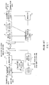
- FIG.1 illustrates the configuration to implement the transmission power control method.
- This cellular system consists of a base station apparatus and mobile station apparatuses and communications are normally carried out between a plurality of mobile station apparatuses and one base station apparatus.
- the base station apparatus receives a multiplexed signal from a plurality of mobile stations through antenna 1 and outputs it to analog receiver 2.
- Analog receiver 2 carries out processing such as amplification and frequency conversion of the received signal and the processed signal is supplied to digital receiver 3 for mobile stations.
- Digital receiver 3 separates a signal of a specific mobile station from the multiplexed received signal by performing correlation detection using a spreading code used on the mobile station side and outputs it to baseband processing circuit 4 and reception level detection circuit 6.
- Baseband processing circuit 4 obtains the reception data from the separated signal. On the other hand, it outputs the transmission data to the above mobile station to modulator 5 as a transmission signal.
- Reception level detection circuit 6 measures the level of the signal received from the above mobile station, generates a power control bit according to the measured level and outputs it to modulator 5. This power control bit is used to control the transmission power of the above mobile station.
- Modulator 5 multiplies the transmission signal from baseband processing circuit 4 and power control bit from reception level detection circuit 6 by a spreading code assigned to the above mobile station and outputs the result to adder 7.
- Adder 7 multiplexes spread signals for a plurality of mobile stations from the modulator. The multiplexed signal is subjected to processing such as conversion to RF frequency and amplification, then transmitted from antenna 1.
- the mobile station apparatus receives a signal from the base station through antenna 8 and outputs it to analog receiver 9.
- Analog receiver 9 carries out processing such as amplification and frequency conversion on the received signal and outputs the processed signal to digital receiver 10. Furthermore, analog receiver 9 is provided with an overall power level measuring circuit for the received signal and the measured power level is input to transmission level control circuit 13.
- Digital receiver 10 separates a signal directed to itself from the spread and multiplexed signal through correlative detection and outputs it to baseband processing circuit 11. It also extracts a power control bit from the separated signal and outputs it to transmission level control circuit 13. Baseband processing circuit 11 obtains reception data from the separated signal. At the same time, it outputs the transmission data to the base station as a transmission signal to modulator 12.
- Modulator 12 spreads the transmission signal from baseband processing circuit 11 by multiplying it by the assigned spreading code and outputs the result to transmission level control circuit 13.
- Transmission level control circuit 13 controls the transmission power of the spread signal using the overall power level from analog receiver 9 and the power control bit extracted from the received signal.
- the output signal of transmission level control circuit 13 is subjected to processing such as conversion to RF frequency and amplification, then transmitted from antenna 8.
- the transmission power control method in the cellular system configured as shown above controls the transmission power level using the overall power level measured by analog receiver 2 of the mobile station apparatus. This compensates variations of the central value of the reception level of the base station caused by the varying distance between the mobile station and base station as the mobile station moves. This method is called a "transmission power control method based on an open loop.”
- the power control bit is determined so that the transmission level of the mobile station may be raised, and to the contrary if it is higher than the reference level, the power control bit is determined so that the level of the mobile station may be lowered, and these power control bits are transmitted to the mobile station.
- the mobile station controls the transmission level using the power control bit extracted by digital receiver 10 and carries out compensation for variations of instantaneous values due to fading which is different for the uplink (mobile stations ⁇ base station) and downlink (base station ⁇ mobile station).
- This method is called a "transmission power control method based on a closed loop.”
- the direct sequence CDMA system uses transmission power control methods based on an open loop and closed loop.
- the CDMA system uses codes with high orthogonality as spreading codes to suppress interference between spreading codes. This allows the capacity of the system to be expanded.
- codes with high orthogonality In Walsh codes and orthogonal Gold codes known as codes with high orthogonality, the number of mutually orthogonal codes is limited to the same number of code length. Therefore, in order to secure the number of spreading codes assigned to the user, a method of combining short codes which have the same cycle as the length of the information symbol and long codes which have longer cycle than that of short codes is adopted.
- the uplink since the distance between a mobile station and the base station varies among a plurality of mobile stations and spreading code timing of the received signal in the base station differs from one mobile station to another, it is not possible to maintain the orthogonality of codes. Therefore, the number of users cannot be limited by the code length on the uplink.
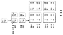
- Hierarchic type orthogonal codes such as Walsh codes are generated by combining generation matrices hierarchically as shown in FIG. 2, characterized by any two spreading codes in any hierarchy being mutually orthogonal.
- C10 to C13 are mutually orthogonal
- C20 to C27 are mutually orthogonal.
- both C20 and C24 consist of elements of C10 and elements with their codes inverted, and thus C20 and C24 are orthogonal to C11 to C13 excluding C10.
- a same communication information rate is used for the uplink and downlink, but when performing multi-media services in a cellular system such as data communications, the information rate can be asymmetric between the uplink and downlink.
- communications whose information rate is asymmetric between the uplink and downlink, for example when information is only sent from the mobile station side are called “asymmetric communications” and communications whose information rate is almost identical between the uplink and downlink are called “symmetric communications.”
- a CDMA communication apparatus comprising a frame assembly section for assembling frames with a known reference signal and transmission power bit and a transmission rate control section for setting a lower transmission rate of a transmission signal composed of the known reference signal and transmission power bit above than the transmission rate for symmetric communications.
- FIG.3 is a block diagram showing the configuration of a CDMA mobile communication system according to Embodiment 1 of the present invention.
- This mobile communication system consists of CDMA communication apparatuses such as a base station apparatus and mobile station apparatuses.
- the base station apparatus comprises encoder 101, pilot signal generator 102, frame configuration section 103, spreader 105, spreading code determination section 121, transmission signal amplitude control section 106, addition section 107, transmission RF section 108, antenna 109, reception RF section 110, correlator 111, decoder 112, reception SIR measuring instrument 113, and transmission power control bit generator 104.
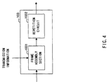
- Frame configuration section 103 in the base station apparatus comprises frame assembly section 1031 that assembles encoded data into frames and repetition circuit 1032 that performs repetition processing which is processing for transmission rate control on the frame-assembled frame data during asymmetric communications.
- Spreading code determination section 121 comprises, as shown in FIG.5, operating spreading code control section 1211 that controls spreading codes used for mobile stations under its control, code comparison section 1212 that compares spreading codes stored in memory 1213 in the case of asymmetric communications, determination section 1214 that determines spreading codes available based on the comparison result and code assignment section 1215 that assigns spreading codes to a specific downlink based on information on the spreading codes in use and the determination result as necessary.
- Memory 1213 stores hierarchic orthogonal type spreading codes such as Walsh codes.
- the mobile station apparatus comprises antenna 114, reception RF section 115, correlator 116, decoder 117, transmission power control section 118, transmission RF section 120 and transmission baseband processing section 119.
- transmission data for a mobile station are input to encoder 101, subjected to encoding processing, etc. and output to frame configuration section 103. Furthermore, pilot signal generator 102 generates a pilot signal whose data pattern is fixed (known reference signal, pilot symbol for example) and outputs it to frame configuration section 103.
- frame configuration section 103 the output of encoder 101, the pilot signal from pilot signal generator 102 and the transmission power control bit from transmission power control bit generator 104 are input and they are assembled into a frame. That is, the above signals are assembled into frame data in frame assembly section 1031 of frame configuration section 103.
- frame configuration section 103 sets a low transmission rate through repetition processing by repetition circuit 1032 based on transmission information indicating asymmetric communications and configures a frame with only a pilot signal and transmission power control bit.
- the frame-configured data are output to spreader 105.
- Spreader 105 uses a spreading code determined by spreading code determination section 121 to perform spreading processing on the frame-configured data and outputs the spread signal to transmission signal amplitude control section 106.
- spreading code determination section 121 inputs transmission information as to whether the communication is symmetric or asymmetric to operating spreading code control section 1211. If the transmission information indicates that the communication is symmetric, operating spreading code control section 1211 extracts an unused spreading code with reference to memory 1213 according to the operating situation of the spreading codes and outputs it to code assignment section 1215. Code assignment section 1215 assigns the spreading code input to a specific downlink.
- operating spreading code control section 1211 extracts a spreading code included in a hierarchy of spreading codes longer than the spreading code used on the symmetric communication lines with reference to memory 1213.
- the extracted spreading code is sent to code comparison section 1212 where it is compared with the spreading code in use which is controlled by operating spreading code control section 1211.
- Comparison here is made by examining whether the component unit of the operating spreading code is used for the spreading code extracted.
- the comparison result is sent to determination section 1214 which then judges whether it can be used as the spreading code for the downlink in asymmetric communication.
- the spreading code which determination section 1214 judges usable is sent to code assignment section 1215 where the spreading code sent is assigned to a specific downlink.
- Transmission signal amplitude control section 106 controls the amplitude of the signal input and outputs the signal to adder 107.
- Adder 107 adds up the output of transmission signal amplitude control section 106 and signals from the transmission sections of other mobile stations and outputs the result to transmission RF section 108.
- Transmission RF section 108 performs modulation and frequency conversion on the input and this transmission signal is transmitted from antenna 109.
- the signal received through antenna 109 from a mobile station is subjected to frequency conversion and demodulation by reception RF section 110 and output to correlator 111 and the reception processing section for other mobile stations.
- the signal is despread with the spreading code used on the mobile station side and the desired wave signal is separated from the received signal.
- the separated and despread data are output to decoder 112 and reception SIR (signal to interference ratio) measuring instrument 113.
- Decoder 112 decodes the input and obtains received data.
- Reception SIR measuring instrument 113 measures reception SIR from the received signal and the measurement result is output to transmission power control bit generator 104.
- Transmission power control bit generator 104 compares the reception SIR input and reference SIR and controls the reception SIR so that it can approximate to the reference SIR, that is, generates a transmission power control bit for the mobile station so as to reduce the difference between the reference SIR and reception SIR.
- the transmission power control bit is output to frame configuration section 103.
- the signal received through antenna 114 from the base station is output to reception RF section 115.
- Reception RF section 115 performs frequency conversion and demodulation on the input and outputs it to correlator 116.
- Correlator 116 carries out despreading using the spreading code used on the base station side and outputs the despread data to decoder 117.
- Decoder 117 decodes the input and obtains received data. It also obtains a transmission power control bit and outputs this transmission power control bit to transmission power control section 118. Transmission power control section 118 uses the transmission power control bit sent from the base station to determine the transmission power and outputs it to transmission RF section 120.
- transmission data for the base station are subjected to transmission path encoding and spreading processing in transmission baseband processing section 119 and output to transmission RF section 120.
- Transmission RF section 120 carries out modulation and frequency conversion on the input and transmits this transmission signal from antenna 114.
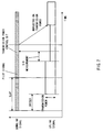
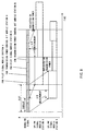
- FIG.6 is a timing chart of a signal under normal transmission power control.
- the downlink signal is a signal made up of a pilot signal, transmission power control bit and transmission data time-multiplexed in slot units by frame configuration section 103 and it is transmitted in such a frame configuration from the base station.
- the pilot signal is a signal which has a fixed information pattern and is used by the mobile station to estimate the transmission path for demodulation.
- the uplink signal is also transmitted as a signal slot cycles as with the downlink signal.
- an offset is provided for the downlink. The offset is set appropriately so that it may be reflected on the transmission power of the uplink.
- SIR measuring instrument 113 measures the reception SIR of the signal at the start of a slot of an uplink signal.
- the reception SIR represents the line quality.
- the measured reception SIR is sent to transmission power control bit generator 104 and is compared by transmission power control bit generator 104 with a reference SIR provided beforehand as the required quality.
- transmission power control bit generator 104 If the reception SIR is lower than the reference SIR, transmission power control bit generator 104 generates a transmission power control bit as a command ordering that the transmission power of the mobile station be increased and if the reception SIR is higher than the reference SIR, it generates a transmission power control bit as a command ordering that the transmission power of the mobile station be decreased and notifies it to the mobile station with the next slot.
- the mobile station extracts this transmission power control bit from the received signal and transmission power control section 118 determines the transmission power value from the transmission power control bit (command to increase/decrease the transmission power) and makes it reflect on the transmission power at the start of the next uplink slot. That is, the mobile station determines the transmission power according to commands of increasing/decreasing the transmission power from the base station and makes it reflect on the next uplink slot.
- the only signals transmitted on the downlink are pilot signals and transmission power control bits, and thus the carrier rate is extremely reduced.
- the transmission rate By controlling the transmission rate in this way, it is possible to send a signal with its transmission power reduced by transmission signal amplitude control section 106.
- a long hierarchic orthogonal type code is used as a spreading code used by spreader 105.
- signals can be transmitted with transmission power reduced, making it possible to reduce interference with other mobile stations.
- C20 uses C10 which is a spreading code one hierarchy ahead as its element. Therefore, C20 cannot maintain orthogonality with C10 and can no longer be used as a spreading code used normally for the downlink.
- C24 is assigned as a spreading code for the downlink. Like C20, C24 has C10 as its element and cannot maintain orthogonality with C10.
- C20 and C24 are mutually orthogonal. Therefore, C20 and C24 which cannot be used as spreading codes for a normal downlink can be used as spreading codes for pilot signals and transmission power control bits. As a result, it is possible to increase the number of users without reducing the number of spreading codes used for a normal downlink.
- spreading codes which cannot be used for a normal downlink are used as spreading codes for pilot signals and transmission power control bits for asymmetric communications, making it possible to secure a lot of spreading codes while maintaining orthogonality.
- This makes it possible to utilize spreading code resources effectively and increase the number of users. Furthermore, it allows the transmission rate to be reduced for pilot signals and transmission power control bits, thus suppressing interference with other mobile stations.
- the present invention can also be implemented by dividing a slot of the downlink into a plurality of subslots and using each subslot as a downlink signal for a different asymmetric communication user.
- spreading codes of the downlink can be used more efficiently, and thus more users can be accommodated within the system.
- Transmission power control of the base station can also be applied to this case.
- the CDMA communication apparatus uses hierarchic orthogonal type spreading codes, sets low transmission rates of the downlink in asymmetric communications with the uplink alone, for example, and transmits transmission power control bits on the downlink using spreading codes of a hierarchy of long codes.
- it is capable of performing open-loop transmission power control for the uplink during asymmetric communication with only the uplink while avoiding a shortage of spreading codes on the downlink.
Landscapes
- Engineering & Computer Science (AREA)
- Computer Networks & Wireless Communication (AREA)
- Signal Processing (AREA)
- Quality & Reliability (AREA)
- Mobile Radio Communication Systems (AREA)
Applications Claiming Priority (2)
| Application Number | Priority Date | Filing Date | Title |
|---|---|---|---|
| JP07831698A JP3904716B2 (ja) | 1998-03-10 | 1998-03-10 | Cdma移動通信システム |
| JP7831698 | 1998-03-10 |
Publications (1)
| Publication Number | Publication Date |
|---|---|
| EP0942541A2 true EP0942541A2 (fr) | 1999-09-15 |
Family
ID=13658543
Family Applications (1)
| Application Number | Title | Priority Date | Filing Date |
|---|---|---|---|
| EP19990102883 Withdrawn EP0942541A2 (fr) | 1998-03-10 | 1999-03-04 | Système de communication à AMDC avec contrÔle de la puissance de transmission |
Country Status (6)
| Country | Link |
|---|---|
| US (1) | US6661783B1 (fr) |
| EP (1) | EP0942541A2 (fr) |
| JP (1) | JP3904716B2 (fr) |
| KR (1) | KR100332271B1 (fr) |
| CN (1) | CN1237839A (fr) |
| CA (1) | CA2265134A1 (fr) |
Cited By (5)
| Publication number | Priority date | Publication date | Assignee | Title |
|---|---|---|---|---|
| WO2001026406A1 (fr) * | 1999-10-07 | 2001-04-12 | Matsushita Electric Industrial Co., Ltd. | Dispositif de communication sans fil et procede de commande de puissance d'emission |
| WO2001095515A1 (fr) * | 2000-06-05 | 2001-12-13 | Linkair Communications, Inc. | Procede de tramage et systeme hertzien synchrone associe |
| GB2368242A (en) * | 2000-06-27 | 2002-04-24 | Nec Corp | Dynamic assignment of spreading codes to a channel in accordance with traffic |
| WO2002054622A1 (fr) * | 2001-01-02 | 2002-07-11 | Nokia Corporation | Procede de commande de puissance a boucle ouverte et selection de debit binaire |
| EP1204225A4 (fr) * | 2000-06-26 | 2003-05-28 | Matsushita Electric Industrial Co Ltd | Dispositif de station de base et procede de communication |
Families Citing this family (10)
| Publication number | Priority date | Publication date | Assignee | Title |
|---|---|---|---|---|
| US6301237B1 (en) | 1997-12-30 | 2001-10-09 | Matsushita Electric Industrial Co., Ltd. | CDMA radio multiplex transmitting device and a CDMA radio multiplex receiving device |
| JP2001186082A (ja) * | 1999-12-24 | 2001-07-06 | Matsushita Electric Ind Co Ltd | Cdma移動通信システム及び方法 |
| KR100797460B1 (ko) | 2001-09-18 | 2008-01-24 | 엘지전자 주식회사 | 역방향 링크 데이터 레이트 제어 방법 |
| JP4592994B2 (ja) * | 2001-03-29 | 2010-12-08 | Necエンジニアリング株式会社 | 送信電力制御システム及びその方法並びにそれに用いる基地局 |
| US9629030B2 (en) * | 2003-10-14 | 2017-04-18 | Qualcomm Incorporated | Data rate control in soft handoff and during cell-switching |
| CN100375395C (zh) * | 2004-08-04 | 2008-03-12 | 中兴通讯股份有限公司 | 码分多址移动通信系统导频发射机 |
| JP4760904B2 (ja) * | 2006-02-17 | 2011-08-31 | 日本電気株式会社 | 帯域制限方法及び無線通信システム |
| US20090312044A1 (en) * | 2008-06-13 | 2009-12-17 | Ari Hottinen | Channel Estimation, Scheduling, and Resource Allocation using Pilot Channel Measurements |
| US8995560B2 (en) * | 2011-10-26 | 2015-03-31 | Google Technology Holdings LLC | Power detection of individual carriers of a multiple-carrier wideband signal |
| JP2015162696A (ja) * | 2014-02-26 | 2015-09-07 | 京セラ株式会社 | 通信機器及び制御方法 |
Family Cites Families (8)
| Publication number | Priority date | Publication date | Assignee | Title |
|---|---|---|---|---|
| US5056109A (en) | 1989-11-07 | 1991-10-08 | Qualcomm, Inc. | Method and apparatus for controlling transmission power in a cdma cellular mobile telephone system |
| US5257283A (en) | 1989-11-07 | 1993-10-26 | Qualcomm Incorporated | Spread spectrum transmitter power control method and system |
| US5265119A (en) | 1989-11-07 | 1993-11-23 | Qualcomm Incorporated | Method and apparatus for controlling transmission power in a CDMA cellular mobile telephone system |
| EP0715440B1 (fr) | 1994-06-22 | 2004-06-16 | NTT DoCoMo, Inc. | Detecteur synchrone et procede de synchronisation pour un recepteur numerique de telecommunications |
| US5719898A (en) | 1995-09-29 | 1998-02-17 | Golden Bridge Technology, Inc. | Fuzzy-logic spread-spectrum adaptive power control |
| FI104142B (fi) * | 1996-10-25 | 1999-11-15 | Nokia Mobile Phones Ltd | Radioresurssien käytön ohjausmenetelmä |
| US5963548A (en) * | 1997-01-21 | 1999-10-05 | Nokia Mobile Phones Limited | Apparatus and method for configuring a data channel for symmetric/asymmetric data transmission |
| US6377817B1 (en) * | 1999-05-03 | 2002-04-23 | Nokia Mobile Phones Ltd. | Asymmetric data transmission for use in a multi-modulation environment |
-
1998
- 1998-03-10 JP JP07831698A patent/JP3904716B2/ja not_active Expired - Fee Related
-
1999
- 1999-03-04 EP EP19990102883 patent/EP0942541A2/fr not_active Withdrawn
- 1999-03-06 KR KR1019990007419A patent/KR100332271B1/ko not_active Expired - Fee Related
- 1999-03-09 US US09/264,856 patent/US6661783B1/en not_active Expired - Lifetime
- 1999-03-10 CN CN99103677A patent/CN1237839A/zh active Pending
- 1999-03-10 CA CA002265134A patent/CA2265134A1/fr not_active Abandoned
Cited By (10)
| Publication number | Priority date | Publication date | Assignee | Title |
|---|---|---|---|---|
| WO2001026406A1 (fr) * | 1999-10-07 | 2001-04-12 | Matsushita Electric Industrial Co., Ltd. | Dispositif de communication sans fil et procede de commande de puissance d'emission |
| US6983165B1 (en) | 1999-10-07 | 2006-01-03 | Matsushita Electric Industrial Co., Ltd. | Radio communication apparatus and transmission power control method |
| WO2001095515A1 (fr) * | 2000-06-05 | 2001-12-13 | Linkair Communications, Inc. | Procede de tramage et systeme hertzien synchrone associe |
| EP1204225A4 (fr) * | 2000-06-26 | 2003-05-28 | Matsushita Electric Industrial Co Ltd | Dispositif de station de base et procede de communication |
| US6738646B2 (en) | 2000-06-26 | 2004-05-18 | Matsushita Electric Industrial Co., Ltd. | Base station device and method for communication |
| US7460880B2 (en) | 2000-06-26 | 2008-12-02 | Matsushita Electric Industrial Co., Ltd. | Communication terminal apparatus and base station apparatus |
| US7761113B2 (en) | 2000-06-26 | 2010-07-20 | Panasonic Corporation | Communication terminal apparatus and base station apparatus |
| GB2368242A (en) * | 2000-06-27 | 2002-04-24 | Nec Corp | Dynamic assignment of spreading codes to a channel in accordance with traffic |
| WO2002054622A1 (fr) * | 2001-01-02 | 2002-07-11 | Nokia Corporation | Procede de commande de puissance a boucle ouverte et selection de debit binaire |
| US6778839B2 (en) | 2001-01-02 | 2004-08-17 | Nokia Corporation | Method and device for transmission power selection and bit rate selection for channels with open loop power control |
Also Published As
| Publication number | Publication date |
|---|---|
| US6661783B1 (en) | 2003-12-09 |
| CA2265134A1 (fr) | 1999-09-10 |
| JP3904716B2 (ja) | 2007-04-11 |
| KR19990077660A (ko) | 1999-10-25 |
| JPH11261481A (ja) | 1999-09-24 |
| CN1237839A (zh) | 1999-12-08 |
| KR100332271B1 (ko) | 2002-04-12 |
Similar Documents
| Publication | Publication Date | Title |
|---|---|---|
| US7006463B2 (en) | CDMA communication system and its transmission power control method | |
| US6542484B1 (en) | Code allocation for radiocommunication systems | |
| JP2993554B2 (ja) | 送信電力制御法および前記送信電力制御法を用いた通信装置 | |
| EP0682419B1 (fr) | Contrôle de puissance de transmission pour un radio mobile utilisant boucle ouverte et fermée | |
| EP0809365B1 (fr) | Commande des puissances pendant la commutation douce dans un système de communication mobile à accès multiple par division de code | |
| US6480479B1 (en) | CDMA cellular radio transmission system | |
| US6504832B1 (en) | Channel assigning device and method using quasi-orthogonal code in a CDMA communication system | |
| JP3078330B2 (ja) | Cdma通信システムにおける遠隔送信機電力制御 | |
| KR100431387B1 (ko) | 이동국 장치 및 송신 전력 제어 방법 | |
| EP1117195A2 (fr) | Station de base et procédé de commande de la puissance de transmission | |
| KR100526523B1 (ko) | 이동통신시스템에서 순방향 공통전력제어채널의 전력을제어하기 위한 장치 및 방법 | |
| US6661783B1 (en) | CDMA transmission apparatus | |
| EP0986192A2 (fr) | Appareil de communication de station mobile,appareil de communication de station base et procédé de communication radio pour le contrôle de la puissance de transmission | |
| KR20030035040A (ko) | 이동통신시스템의 핸드오프시 역방향 전력제어채널의전송제어를 위한 방법 및 장치 | |
| US6618427B1 (en) | Spread spectrum communication system and base station thereof | |
| EP1156600A1 (fr) | Terminal et procede amcr | |
| KR20020016634A (ko) | 이동국 장치, 기지국 장치 및 무선 통신 방법 | |
| JP3248667B2 (ja) | 送信電力制御方法 | |
| US6973063B1 (en) | Methods, systems and apparatus for precompensating for interference among transmitted coded signals | |
| JP3581049B2 (ja) | フレーム構成方法、フレーム構成装置、フレーム構成、送信電力制御方法および無線局 | |
| JP3215699B1 (ja) | 送信電力制御方法 | |
| KR100616356B1 (ko) | 대역 확산 시스템의 고속 순방향 서플리멘털 채널에 대한데이터 전송 속도 결정 방법 |
Legal Events
| Date | Code | Title | Description |
|---|---|---|---|
| PUAI | Public reference made under article 153(3) epc to a published international application that has entered the european phase |
Free format text: ORIGINAL CODE: 0009012 |
|
| AK | Designated contracting states |
Kind code of ref document: A2 Designated state(s): AT BE CH CY DE DK ES FI FR GB GR IE IT LI LU MC NL PT SE |
|
| AX | Request for extension of the european patent |
Free format text: AL;LT;LV;MK;RO;SI |
|
| STAA | Information on the status of an ep patent application or granted ep patent |
Free format text: STATUS: THE APPLICATION HAS BEEN WITHDRAWN |
|
| 18W | Application withdrawn |
Effective date: 20030128 |