EP0942585A2 - Bildverarbeitungsverfahren und -Gerät und Aufzeichnungsgerät - Google Patents
Bildverarbeitungsverfahren und -Gerät und Aufzeichnungsgerät Download PDFInfo
- Publication number
- EP0942585A2 EP0942585A2 EP99301829A EP99301829A EP0942585A2 EP 0942585 A2 EP0942585 A2 EP 0942585A2 EP 99301829 A EP99301829 A EP 99301829A EP 99301829 A EP99301829 A EP 99301829A EP 0942585 A2 EP0942585 A2 EP 0942585A2
- Authority
- EP
- European Patent Office
- Prior art keywords
- density
- ink
- recording
- pixel
- superimpose
- Prior art date
- Legal status (The legal status is an assumption and is not a legal conclusion. Google has not performed a legal analysis and makes no representation as to the accuracy of the status listed.)
- Withdrawn
Links
Images











Classifications
-
- H—ELECTRICITY
- H04—ELECTRIC COMMUNICATION TECHNIQUE
- H04N—PICTORIAL COMMUNICATION, e.g. TELEVISION
- H04N1/00—Scanning, transmission or reproduction of documents or the like, e.g. facsimile transmission; Details thereof
- H04N1/23—Reproducing arrangements
- H04N1/2307—Circuits or arrangements for the control thereof, e.g. using a programmed control device, according to a measured quantity
- H04N1/2346—Circuits or arrangements for the control thereof, e.g. using a programmed control device, according to a measured quantity according to a detected condition or state of the reproducing device, e.g. temperature or ink quantity
-
- G—PHYSICS
- G06—COMPUTING OR CALCULATING; COUNTING
- G06K—GRAPHICAL DATA READING; PRESENTATION OF DATA; RECORD CARRIERS; HANDLING RECORD CARRIERS
- G06K15/00—Arrangements for producing a permanent visual presentation of the output data, e.g. computer output printers
- G06K15/02—Arrangements for producing a permanent visual presentation of the output data, e.g. computer output printers using printers
- G06K15/10—Arrangements for producing a permanent visual presentation of the output data, e.g. computer output printers using printers by matrix printers
- G06K15/102—Arrangements for producing a permanent visual presentation of the output data, e.g. computer output printers using printers by matrix printers using ink jet print heads
-
- H—ELECTRICITY
- H04—ELECTRIC COMMUNICATION TECHNIQUE
- H04N—PICTORIAL COMMUNICATION, e.g. TELEVISION
- H04N1/00—Scanning, transmission or reproduction of documents or the like, e.g. facsimile transmission; Details thereof
- H04N1/23—Reproducing arrangements
- H04N1/2307—Circuits or arrangements for the control thereof, e.g. using a programmed control device, according to a measured quantity
-
- H—ELECTRICITY
- H04—ELECTRIC COMMUNICATION TECHNIQUE
- H04N—PICTORIAL COMMUNICATION, e.g. TELEVISION
- H04N1/00—Scanning, transmission or reproduction of documents or the like, e.g. facsimile transmission; Details thereof
- H04N1/40—Picture signal circuits
- H04N1/40087—Multi-toning, i.e. converting a continuous-tone signal for reproduction with more than two discrete brightnesses or optical densities, e.g. dots of grey and black inks on white paper
-
- G—PHYSICS
- G06—COMPUTING OR CALCULATING; COUNTING
- G06K—GRAPHICAL DATA READING; PRESENTATION OF DATA; RECORD CARRIERS; HANDLING RECORD CARRIERS
- G06K2215/00—Arrangements for producing a permanent visual presentation of the output data
- G06K2215/0082—Architecture adapted for a particular function
- G06K2215/0094—Colour printing
Definitions
- the present invention relates to an image processing method and apparatus for generating image data for recording an image by using recording materials having different densities, and a recording apparatus for recording an image by using the recording materials, each having different densities.
- Printing apparatuses such as printers, copying machines, and facsimile apparatuses are designed to print an image consisting of a dot pattern on a printing medium such as a paper sheet or thin plastic plate on the basis of image information.
- Such printing apparatuses are classified according to their printing schemes into an ink-jet type, wire dot type, thermal type, laser beam type, and the like.
- the ink-jet type (ink-jet printing apparatus) is designed to print an image by discharging/spraying ink (printing solution) droplets from the orifices of a print head and making them adhere to a printing medium.
- ink-jet printing apparatuses an apparatus using a print head having an array of a plurality of orifices to realize high printing speed and an apparatus having a plurality of print heads to be capable of color printing have been widely used.
- halftone processing methods such as a dither method and an error diffusion method are used in these ink-jet printing apparatuses as methods of faithfully reproducing the gradation of image information.
- a printing apparatus has a high resolution (1,000 dots/inch or more)
- excellent gradation printing can be performed.
- a printing apparatus has a low resolution (about 360 to 720 dots/inch)
- the printed dots of a highlight portion become conspicuous, and the discontinuity of pixels tends to make an image look rough.
- a method of converting each print dot itself into a multilevel dot is used.
- the voltage to be applied to a print head, the pulse width, or the like is controlled to modulate the diameter of each print dot adhering to a printing medium, thereby reproducing gradation.
- such a method is highly environment-dependent, and hence the diameters of print dots remain unstable, and there is a limit to the minimum size of a print dot that can be printed. It is therefore difficult to stably reproduce gradation.
- a density modulation method is also available, in which the density of dots in a dot matrix (predetermined area) is changed while the dot size remains the same.
- a considerably large area is required to increase the number of gradation levels, and hence the resolution decreases.
- a suction means and pressurizing means are used to remove foreign substances and bubbles from liquid paths by discharging ink from the nozzles of the print head.
- ink coagulations near orifices are removed by cleaning the ink discharge surfaces with a wiper.
- the orifice surfaces of the print head are wiped at a predetermined timing.
- preliminary discharging which differs from discharging for printing, is performed at a predetermined timing. With this operation, fresh ink is always supplied into each nozzle to perform stable printing.
- the present invention has been made in consideration of the prior art described above, and has as an object to provide an image processing method and apparatus in which when a plurality of recording materials are to be recorded and overlaid in accordance with the density of image data, density changes of these recording materials are predicted, and data for determining recording materials to be used for recording are generated on the basis of the predicted density values, and a recording apparatus for recording an image by using these recording materials.
- It is still another object of the present invention provide an image processing method and apparatus for predicting density changes of recording materials in the above manner, performing recording upon determining recording materials to be used for recording on the basis of the predicted density values, and performing density interpolation by distributing, to pixels around a target pixel, the error between the density value of the target pixel to be recorded and the actual density value of the image data, thereby generating image data with improved gradation reproducibility, and a recording apparatus for recording an image by using these recording materials.
- An ink/film system having an additive property is a system in which when an image is to be printed on a transparency film, which is used to print a transmission image, by using the ink-jet method, the density of a given pixel increases if ink is superimposed a plurality of number of times at the same pixel position.
- the number of gradation levels can be greatly increased by superimposing a plurality of types of ink, each having different density at the same pixel position.
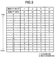
- Fig. 3 shows the contents of an ink type distribution table to explain how plural types of ink are discharged in accordance with image data (density data).
- the number of gradation levels per pixel having the color can be set to the maximum number, i.e., 2 n , by combining n types of ink represented by density ratios of 1 : 2 : ⁇ ⁇ ⁇ :2 i-1 : ⁇ ⁇ ⁇ :2 n-1 .
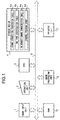
- Fig. 1 is a block diagram showing the construction of an ink-jet printing apparatus according to the first embodiment.
- reference numeral 1 denotes an image input unit such as a scanner
- numeral 2 denotes an operation unit having various keys for setting various parameters and designating a print start
- numeral 3 denotes a CPU for controlling the overall printing apparatus according to various programs stored in a storage medium 4.
- the storage medium 4 stores programs such as control programs and error processing programs for operating this printing apparatus. All the operations of this embodiment are executed on the basis of this program.
- a ROM, FD, CD-ROM, HP, memory card, magnetooptic disk, or the like can be used as the storage medium 4 storing such programs.
- the storage medium 4 includes a gamma correction conversion table 4a to be referred to in gamma conversion processing, an ink type distribution table 4b to be referred to in ink type distribution processing to be described later, an ink density change characteristic table 4e storing data that indicates the degrees of increases in ink density with respect to non-discharge times and is referred to during multilevel gradation processing and ink type distribution processing, and a control program group 4d storing various programs.
- Reference numeral 5 denotes a RAM that is used as a work area for various programs stored in the storage medium 4, a temporary saving area in error processing, and a work area in image processing.
- Reference numeral 6 denotes an image processing unit for generating a discharge pattern for realizing multilevel gradation by the ink-jet method on the basis of input image data
- numeral 7 denotes a printer unit (printer engine) for forming a dot image on a printing medium such as print paper on the basis of the print data generated by the image processing unit 6 in image printing operation
- numeral 8 denotes a bus line that is used to connect the components described above and transmit address signals, data, control signals, and the like.
- the image processing unit 6 in the first embodiment will be described next with reference to Figs. 2A and 2B.
- Fig. 2A shows the flow of processing in the image processing unit 6 in the first embodiment.
- An image signal CV input by the image input unit 1 is input to gamma correction processing 11.
- the signal is converted into a density signal CD indicating a density by referring to the gamma correction conversion table 4a.
- the image density signal CD having undergone gamma correction in this manner is stored in a page memory area in the image processing work area of the RAM 5.
- Target pixel selection processing 12 is performed to select one pixel, in the page memory area in the RAM 5, which is to be processed, and obtain the density data CD of the selected pixel.
- Ink type distribution processing 13 is performed to refer to the ink type distribution table 4b on the basis of the density value (CD value) of the target pixel selected by the target pixel selection processing 12, and select an ink combination candidate for expressing the density CD of the target pixel.
- Density change correction processing 14 is performed to calculate the nonuse time of each nozzle and predict a specific variation in the density obtained by the ink combination selected by the ink type distribution processing 13 with respect to the ideal density by referring to the ink density change characteristic table 4e, which is linearly approximated by the least squares method.
- the ink combination selected by the ink type distribution processing 13 is changed, as needed, to determine the optimal ink density combination, i.e., the binary data d1, d2, d3,... that indicate the discharging/non-discharging of ink (heads) corresponding to the respective pixel densities.
- binary data for the target pixel are determined, and the respective binary data are sent to the corresponding ink-jet head units to execute printing.
- Fig. 2B shows a modification of the first embodiment.
- the same reference numerals in Fig. 2B denote the same parts as in Fig. 2A, and a description thereof will be omitted.
- the error between the print density of the target pixel, which is printed after the above determination processing, and the density value of the target pixel is calculated, and error diffusion processing 16 is performed to distribute the error to pixels around the target pixel.
- Density error calculation processing 15 is performed to calculate the difference between the CD value of the target pixel and the density that can be expressed by the ink combination determined by the density change correction processing 14.
- the error calculated by the density error calculation processing 15 is diffused to the pixels around the target pixel on the page memory of the RAM 5 in accordance with distribution coefficients.
- the binary data d1, d2, d3,... indicating the discharging/non-discharging of ink per pixel are generated for the respective heads, each of which has ink having different density from each other, by repeating the above processing from the target pixel selection processing 12 to the error diffusion processing 16 with respect to all pixels of the image data input from the image input unit 1.
- the printer unit 7 forms a multilevel gradation image by discharging ink from an orifice array corresponding to the ink-jet head units for discharging ink, each having different density, in accordance with the binary data d1, d2, d3,... determined in this manner.
- reference numerals 17-1, 17-2,... denote delay circuits for adjusting the timings of spraying and superimposing ink at the same pixel position from each orifice array.
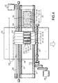
- the printer unit 7 in this embodiment will be described next with reference to Fig. 4.
- Fig. 4 is a schematic view showing the construction of the main part of the printer unit 7 in this embodiment.
- a plurality of ink-jet head units 21-1 to 21-4 are mounted on a carriage 20.
- Each ink-jet head unit 21 has an orifice (nozzle) array for discharging ink.
- the respective ink-jet head units 21 are arranged at predetermined intervals. Consequently, the nozzle arrays of the respective ink-jet head units are arranged at predetermined intervals.
- Each type of ink supplied to the nozzle array of each of the ink-jet head units 21-1 to 21-4 is supplied from each of ink cartridges 22-1 to 22-4.
- the ink cartridges 22-1 to 22-4 are ink cartridges for supplying the inks D1, D2, D3, and D4, respectively. The density of ink stored in each ink cartridge will be described later. Controls signals, print signals, and the like are sent from the image processing unit 6 to these ink-jet head units 21 through a flexible cable 23.
- Reference numeral 24 denotes a printing medium, e. g., print paper, a thin plastic plate, or the like, which is held by a paper discharge roller 25 through a convey roller (not shown) and conveyed in the direction indicated by the arrow during rotation of a convey motor 26;
- numeral 27 denotes a guide shaft for guiding and supporting the traveling of the carriage 20;
- numeral 28 denotes a linear encoder for detecting the traveling position of the carriage 20.
- the carriage 20 is conveyed/driven by a carriage motor 30 through a driving belt 29 to reciprocate along the guide shaft 27.
- Heating elements for generating heat energy for ink discharge are provided inside (liquid paths) the orifices of the ink-jet head units 21 described above.
- the heating elements are driven on the basis of print data in accordance with the read timing of the linear encoder 28 to spray ink droplets onto the printing medium 24 in the order of the inks D1, D2, D3, and D4 and make the droplets adhere thereto, thereby forming an image on the printing medium 24.
- a recovery unit 32 having a cap unit 31 (including caps 31-1 to 31-4) is mounted at the home position of the carriage 20 which is set outside a printable area by the ink-jet head units 21.
- the carriage 20 is moved to the home position, and the caps 31-1 to 31-4 of the cap unit 31 are used to close the orifices of the corresponding ink-jet head units 21-1 to 21-4, thereby preventing the respective ink-jet head units from clogging up due to the coagulation of ink inside the orifices upon evaporation of the ink solvent or the adhesion of foreign substances such as dust.
- the cap unit 31 is used to prevent orifices exhibiting low printing frequencies from causing discharge failures or clogging by performing idling discharge operation, i.e., discharging ink to the cap unit 31 at some distance from the orifices, or is used to perform discharge recovery operation for orifices that have caused discharge failures by driving a pump (not shown) to draw ink from the orifices while the orifices are capped with the cap unit 31.
- Reference numeral 33 denotes an ink reservoir to which ink is preliminary discharged from the ink-jet head units 21-1 to 21-4 when they pass over the ink reservoir 33 before printing operation.
- a blade and wiping member can be mounted near the cap unit 31 to clean the orifice formation surfaces of the ink-jet head units 21-1 to 21-4.
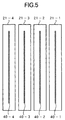
- Fig. 5 is a view showing the arrangement of orifices (nozzles) of the ink-jet head units 21-1 to 21-4 when viewed from the printing medium 24 side.
- the arrangement of the orifice arrays in the printer unit 7 and an image forming method according to this embodiment will be described with reference to Fig. 5.
- reference numerals 40-1 to 40-4 denote orifice arrays for discharging the inks D1 to D4, respectively.
- the orifice array of each unit has 256 orifices with a 600-dot (600-dpi) per inch in the vertical (sub-scanning) direction.
- a 256-dot wide image in the sub-scanning direction can be formed by superimposing the four types of inks D1 to D4 . This can shorten the print time and form a high-gradation image.
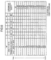
- Fig. 6 shows the arrangement of the ink type distribution table 4b in this embodiment, and more specifically, an ink type distribution table storing binary data indicating ink discharging (1)/non-discharging (0) of the inks D1, D2, D3, and D4 in correspondence with image data (density data), the transmission densities of the inks D1, D2, D3, and D4, and superimposed transmission densities of superimposed discharge obtained by ink combinations.
- each density data is expressed by eight bits, with a smaller value representing a lower density (thin) and a larger value representing a higher density (thick).
- the transmission density of a transparency film as a printing medium is set to "OD".
- the transmission densities of the inks D1, D2, D3, and D4 are expressed by the transmission densities obtained when 100% solid printing is performed by using each of types of the ink alone.
- the density ratio of the inks D1, D2, D3, and D4 is "1 : 2 : 4 : 8".
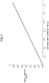
- Fig. 7 is a graph showing the density increase rate with respect to the non-discharge time of ink. This value is obtained by linearly approximating representative densities by the least squares method on the basis of experimental results.
- the abscissa represents the continuous non-discharge time of ink; and the ordinate denotes the increase rate of the transmission density (OD) of ink.
- the "non-discharge time” is the time interval between the instant at which ink is discharged from one nozzle of an ink-jet head unit and the instant at which ink is discharged next from this nozzle.
- ink is discharged from the nozzle array of the ink-jet head unit 21 of the ink-jet printing apparatus at a frequency of 10 kHz.
- 10,000 ink droplets are discharged from the nozzle array of the ink-jet head unit 21 with a 600-dpi pitch.
- the carriage 20 scans a short side of an A3 sheet in about 0.7 sec at about 423.3 mm/sec.
- the increase rate of the density of ink used in this embodiment is proportional to the continuous non-discharge time during scanning of the carriage 20 over a short side (297 mm) of an A3 sheet.
- An increase in ink density during scanning for printing operation results from the evaporation of the ink solvent at each nozzle tip. Once the ink whose density has increased at a nozzle tip is discharged as an ink droplet, fresh ink is charged into the nozzle tip. As a result, the ink density at the nozzle tip returns to the specified (original) density before the increase in density.
- the non-discharge time on the abscissa in Fig. 7 is expressed by a continuous non-discharging operation count at a discharge frequency of 10 kHz.
- an ink density increase is predicted on the basis of the continuous non-discharge count in the past by referring to this ink density increase graph, and the ink density value is corrected on the basis of the density increase.
- the ink density characteristics change table 4e (Fig. 9) is generated on the basis of the graph of Fig. 8 to allow the image processing unit 6 for performing image processing to easily refer to an ink density increase.
- the ink density increase rate is 150%.
- the contents of the ink density characteristics change table 4e will be described on the basis of this graph.
- Fig. 9 shows an example of the ink density change characteristics table 4e in this embodiment.
- the values shown in Fig. 9 are based the calculation results based on a density increase rate dD with respect to the continuous non-discharging operation count in Fig. 8, and are written in the ink density characteristics change table 4e in correspondence with the continuous non-discharging operation counts.
- the ink density characteristics change table 4e By generating the ink density characteristics change table 4e, in which the calculation results are written in advance, the calculation amount in the image processing unit 6 can be reduced, resulting in an increase in processing speed.
- the density increase rate dD is 4-byte data, an address offset occurs every four addresses in the ink density characteristics change table 4e.
- a continuous non-discharging operation count corresponds to an address offset, and can be made to correspond to the address by multiplying the non-discharge count by four. This value is added to the base address in the ink density characteristics change table 4e to obtain an access address.
- a density increase rate can be obtained by reading out the contents at the address.
- the ink density at the corresponding time can be predicted by multiplying this density increase rate by the original ink density to be obtained.
- Figs. 10A and 10B are schematic views showing the main scanning of the printer unit 7 in Fig. 4.
- Fig. 10A is a view showing the printing unit of the printer unit 7 when viewed from a side parallel to the recording surface of the printing medium 24 (direction parallel to Fig. 4).
- Fig. 10B is a view showing the printing medium 24 on the printing unit when viewed from above (direction perpendicular to Fig. 4).
- the carriage 20, on which the ink-jet head units 21-1 to 21-4 are mounted starts to move from the home position (not shown) in the direction indicated by an arrow S.
- the carriage 20 moves at a constant speed when the ink-jet head unit 21-1 passes over the ink reservoir 33.
- the ink-jet head units 21-1 to 21-4 pass over the ink reservoir 33 in the order named and preliminary discharge ink to the ink reservoir 33 at a position A (the position of the ink reservoir 33).
- a length B - C on the printing medium 24 corresponds to the print area, and printing is started from a position D.
- An image having a width E - F in Fig. 10B is printed in the first scanning operation, and an image having a width F - G is printed in the next scanning operation.
- ink is discharged from the nozzle array of each ink-jet head unit 21 of the ink-jet printing apparatus at a frequency of 10 kHz, and the print density in the main scanning direction is 600 dpi.
- the main scanning speed of the carriage 20 is therefore about 423.3 mm/sec. Assume that the distance from the preliminary discharging position A to the print start position D is 211.7 mm.
- each ink-jet head unit 21 reaches the print start position D on 0.5 sec after preliminary discharging, and starts printing in accordance with print data.
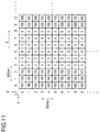
- Fig. 11 shows an example of the density data of image data stored in the page memory area in the image processing work area of the RAM 5 to print an image on the printing medium 24, as shown in Figs. 10A and 10B.
- reference symbols D, E, S, and the like correspond to the respective signals in Figs. 10A and 10B
- one lattice in Fig. 11 corresponds to one pixel data of 600 (dpi) images to be printed.
- print data corresponding to each ink is generated by predicting an ink density from the digital value of the density data instead of the OD value. That is, a 50% increase in OD value is equivalent to a 50% increase in density data.
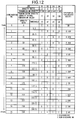
- Fig. 12 shows a table obtained by adding multilevel error diffusion thresholds corresponding to the processing in Fig. 2B and value corresponding to the density data of the transmission density of each type of ink, to the ink type distribution table 4b in Fig. 6.
- Fig. 13 shows an example of how weighting is performed to distribute an error in a target pixel to neighboring pixels of the target pixel in the multilevel error diffusion processing 16 (Fig. 2B) in the modification of the first embodiment described above.
- reference symbol "*" denotes a target pixel.
- the difference (error) between the printed density (OD) and the density data which can be expressed by an ink combination is distributed to the pixels around the target pixel in accordance with the error distribution coefficients shown in Fig. 13.
- the numbers starting from "0", which are assigned to the upper and left sides, indicate the addresses of pixels.
- An arbitrary pixel is indicated by coordinates (x, y) with x and y respectively indicating the horizontal and vertical directions. That is, a pixel (0, 0) indicates the pixel at the upper left position in Fig. 11.
- each pixel row in the main scanning direction corresponds to one nozzle of each of the ink-jet head units 21 with different ink densities.
- the density data of the pixel (0, 0) is "100".
- a combination of the inks D2 and D3, which is indicated by the combination number (No. ) 6, is selected as a candidate.
- the ink densities of both the inks D2 and D3 have increased 50%. It can be predicted from this that the density of the ink D2 has increased from "34" to "51", and the density of the ink P3 has increased from "68" to "102". With the combination of the inks D2 and D3, therefore, the superimpose density becomes "153" which is higher than target density "102" by about 50%.
- the density level of the ideal ink combination obtained from Fig. 12 is "102", and density "100" of the pixel (0, 0) is to be expressed. Since the density of the ink D2 has increased to "51”, the ink D2 is not discharged, and only the ink D3 (predicted density "102") is discharged. With this operation, the predicted print density becomes "102".
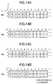
- the ink combination determined in this manner is stored as binary data indicating the discharging/non-discharging of each ink at an address in a corresponding one of memories Md1, Md2, Md3, and Md4 (in Figs. 14A-14D) in correspondence with the pixel.
- the difference/error is difference "-2" obtained by subtracting predicted density "102" that can be expressed from density data "100" of the pixel (0, 0).
- This difference is distributed to the pixels around the target pixel in accordance with the error distribution coefficients in Fig. 13 such that "-1" is distributed to the pixel (1, 0) at the right of the target pixel, and "-0.75" is distributed to the pixel (0, 1) immediately underneath the target pixel.
- the density data of the pixel (1, 0) is changed to "99”
- the density data of the pixel (0, 1) is changed to "99.25".
- the pixel (1, 0) at the right of the target pixel in Fig. 11 is set as the next target pixel.
- the density data of this pixel (1, 0) has become "99" by error diffusion from the pixel (0, 0) described above.
- the combination of the inks D2 and D3 (density value "102"), which is indicated by the combination number (No. 6) is selected as a candidate value nearest to the ideal value by referring to the table in Fig. 12. Since the ink D3 has been discharged to the pixel (0, 0) as described above, the density of the ink D3 is almost restored to the original value. In contrast to this, the density values of the remaining inks have been increased 50% as described above since no preliminary discharging is performed at the position A in Fig. 10A.
- the density levels of the inks D2 and D3 respectively become “51” and “68", and the density level of the combination of the inks D2 and D3 become “118".
- the density value of this ink is "25.5" which is 1.5 times “17”. Consequently, the density value of the combination of the inks D1 and D3 becomes "93.5", and hence the combination of the inks D1 and D3 can express density level "99" of the pixel (1,0) more appropriately than the combination of the inks D2 and D3. In this case, therefore, the inks D1 and D3 are discharged.
- the difference/error is difference "5.5” obtained by subtracting predicted density value "93.5" that can be expressed from density level "99" of the pixel (1, 0).
- This difference is distributed to the pixels around the target pixel in accordance with the error distribution coefficients in Fig. 13 such that "22/8" is distributed to the pixel (2. 0) at the right of the target pixel, “16.5/8” is distributed to the pixel (1, 1) immediately underneath the target pixel, and "5.5/8" is distributed to the lower left of the target pixel.
- These errors are respectively added to the density values of the pixels (2, 0), (1, 1), and (0, 1) around the target pixel.
- the pixel (2, 0) at the right of the target pixel is set as the next target pixel.
- the density data of this pixel (2, 0) has become "102.75" by error diffusion from the pixel (1, 0).
- the combination of the inks D2 and D3, which is indicated by the combination number (No. ) "6" is selected as a combination candidate by referring to the thresholds in Fig. 12. Since these inks D1 and D3 have been discharged to the pixel (1, 0), the densities of the inks D1 and D3 are restored to the original values. In contrast to this, the density values of the remaining inks have been increased 50% as described above since they are not discharged after preliminary discharging.
- the density values of the inks D2 and D3 respectively become “51” and “68", and the density value of the combination of the inks D1 and D3 becomes "118".
- the combination of D2 and D3 can express density level "102.75" of the pixel (2, 0) more appropriately. In this manner, the inks D2 and D3 are discharged to print the pixel (2. 0).
- the difference/error is difference "-15.25” obtained by subtracting predicted density value "118" from image density value "102.75” of the pixel (2, 0).
- This difference is distributed to the pixels around the target pixel in accordance with the error distribution coefficients shown in Fig. 13 such that "-61/8" is distributed to the pixel (3, 0) at the right of the target pixel, "-45.75/8” is distributed to the pixel (2, 1) immediately underneath the target pixel, and "-15.25/8" is distributed to the pixel (1, 1) at the lower left of the target pixel.
- These errors are then added to the density data of these neighboring pixels (3, 0), (2, 1), and (1, 1).
- the above processing is performed for the sequentially selected target pixels in the main scanning direction S on the basis of the density data of the respective pixels of an image, thereby obtaining the binary data d1, d2, d3, and d4 indicating the discharging/non-discharging of ink from the respective ink-jet head units 21, each having different ink density, in units of pixels.
- These data are stored as binary data indicating the discharging/non-discharging of the respective ink at the addresses in the memories Md1, Md2, Md3, and Md4 at which the pixel data (density data) have been stored as shown in Figs. 14A-14D.
- the processing for the pixel data of one main scanning line is complete in this manner, the first pixel (0, 1) on the next scanning line is set as the next target pixel, and processing is started in the main scanning direction S in the same manner as described above.
- processing is started on the basis of a prediction that the density of each ink has increased 50% at the target pixel (0, 1).
- Similar processing is repeated for each scanning line to generate binary data indicating the discharging/non-discharging of each ink. These data are then stored at the addresses in the memories at which the original pixel data have been stored.
- Figs. 14A to 14D show binary data (bit planes) Md1, Md2, Md3, and Md4 indicating the discharging/non-discharging of the inks D1, D2, D3, and D4 and generated in the RAM 5 in this embodiment.
- the ink-jet head units 21-1 to 21-4 are driven in synchronism with the traveling of the carriage 20 in accordance with these binary data. That is, the case shown in Figs.
- the ink-jet head unit 21-1 is driven in accordance with the binary data in Md1; the ink-jet head unit 21-2, in accordance with the binary data in Md2; the ink-jet head unit 21-3, in accordance with the binary data in Md3; and the ink-jet head unit 21-4, in accordance with the binary data in Md4.
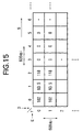
- Fig. 15 shows a case wherein the ink combination is changed on the basis of the ink type distribution table 4b in this embodiment, and printing is performed by driving the respective ink-jet head units on the basis of the binary data shown in Figs. 14A to 14D.
- Fig. 15 shows the actual print density levels (OD) in correspondence with the input density data shown in Fig. 11.
- Fig. 16 is a block diagram showing the schematic arrangement of an ink-jet printing apparatus according to the second embodiment of the present invention.
- the same reference numerals in Fig. 16 denote the same parts as in Fig. 1. Since density error calculation processing 15 and error diffusion processing 16 are the same as those in the first embodiment, a description thereof will be omitted.
- Reference numeral 4e denotes an ink density change characteristics table 4e (Fig. 9), in a storage medium 4, which indicates the ink density change characteristics of ink with respect to the continuous non-discharge time;
- numeral 5 denotes a RAM used as a work area for various programs in the storage medium 4, a temporary saving area in error processing, and a work area for image processing.
- the work area for various programs includes record history counters 5a that count the continuous non-discharging operation counts of the nozzles of the respective ink-jet head units and are used to predict density changes.
- the RAM 5 after the tables in the storage medium 4 are copied, the contents of the tables can be changed, and image processing can be performed while the changed tables are referred to.
- the ink density characteristics change table 4e can be directly generated on the basis of density variation data.
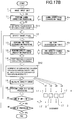
- Fig. 17A is a flow chart for explaining the flow of image processing in an image processing unit 6 in the second embodiment of the present invention. Note that since the arrangement of the ink-jet printing apparatus of the second embodiment is the same as that shown in Fig. 1, a description thereof will be omitted.
- the same reference numerals in Fig. 17A denote the same parts as in Fig. 2.
- Fig. 17A is a flow chart for explaining an example of image processing based on (one-pass) print algorithm for completing printing of an image corresponding to the print head width by one main scanning operation.
- the second embodiment includes the record history counters 5a for storing the print histories of the respective nozzles.
- the number of record history counters 5a is determined by the types of ink used in this ink-jet printing apparatus and the print algorithm. These counters 5a may be arranged in the form of hardware or may be arranged in the RAM 5 as shown in Fig. 16.
- the second embodiment includes the record history counters 5a corresponding to inks D1, D2, D3, and D4. These counters are denoted by reference symbols C1, C2, C3, and C4 (not shown).
- gamma correction processing 11 is performed to convert an image signal CV input from an image input unit 1 into a signal CD representing a density by using a gamma correction conversion table 4a, and stores it in a page memory area in the image processing work area of the RAM 5.
- Initial values are then set in the record history counters 5a corresponding to the respective ink-jet head units 21 (step S11). These initial values are obtained by converting the times required for the respective heads to move from the preliminary discharge position ("A" in Fig. 10A) before print operation to the image print start position ("D" in Fig. 10A) in each scanning operation into the number of dots.
- each pixel data that is stored in the page memory area in the RAM 5 and are to be processed from now on is sequentially selected and read out upon movement of each ink-jet head unit 21, thereby obtaining the density data CD of the pixel.
- an ink combination candidate for expressing the density data CD of the target pixel is selected on the basis of the readout CD value of the target pixel by referring to an ink type distribution table 4b.
- the degree of variation in ink density in actual printing operation with respect to the ideal density is predicted by referring to the ink density change characteristic table 4e (Fig. 9), which is linearly approximated by the least squares method using experimental values, on the basis of the value of the record history counter 5a for each nozzle used to print the pixel.
- binary data d1, d2, d3,... indicating the discharging/non-discharging of the respective ink-jet head units having ink, each having different density, are determined in correspondence with the density data of the target pixel.
- These binary data are respectively sent to the corresponding ink-jet head units to drive them, thereby performing printing operation.
- step S12 processing corresponding to the record history counters C1, C2. C3.... is performed on the basis of the binary data d1, d2, d3,... indicating the discharging/non-discharging of ink from the nozzles of the respective ink-jet head units.
- the record history counter 5a corresponding to each nozzle that is determined as a non-discharging nozzle is counted up (incremented) by one, whereas each nozzle that is determined as a discharging nozzle is set to "1". That is, the value of each record history counter 5a in the second embodiment indicates the consecutive non-discharging count of the corresponding nozzle.
- step S11 initialization of the history counters in step S11 is performed in units of lines to generate the binary data d1, d2, d3,... indicating the discharging/non-discharging of ink from the respective head units having ink, each having different density, in units of pixels.
- Fig. 17B is a flow chart showing a modification of the second embodiment.
- the same reference numerals in Fig. 17B denote the same portions as in Fig. 17A, and a description thereof will be omitted.
- the density change correction processing 14 is performed to calculate a density variation accompanying the ink combination selected by the ink type distribution processing 13 on the basis of the predicted density obtained by the density change prediction processing 10, and the ink combination is changed, as needed, thereby determining an optimal ink density combination, i.e., the binary data d1, d2, d3,... indicating the discharging/non-discharging at the respective ink-jet head units, each having ink with different density from each other, as in the modification of the first embodiment described above.
- Density error calculation processing 15 is performed to calculate the difference between the density data (CD value) of the target pixel and the density that can be expressed by the ink combination determined by the density change correction processing 14 in accordance with additive property, i.e., the density (OD) determined in consideration of density change prediction.
- the difference (error) calculated by the density error calculation processing 15 is diffused to the pixels around the target pixel in the page memory in accordance with the distribution coefficients shown in Fig. 13.
- the target pixel is completely processed.
- the processing from the target pixel selection processing 12 to the error diffusion processing 16 is performed for all the pixels of the image data on the basis of the density data (CD) of the image, thereby generating, in units of pixels, the binary data d1, d2, d3,... indicating the discharging/non-discharging of ink from the respective head units, each having ink with different density from each other.
- CD density data
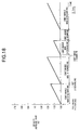
- Fig. 18 is a graph for explaining an example of how the ink density at a given nozzle changes in accordance with ink discharging/non-discharging.
- the ink density increases as a lapse of time in the interval between preliminary discharging and discharging of first one-dot ink, returns to the original density after one ink discharging operation, and increases again with time when the ink non-discharge state continues.
- the ink density at the nozzle does not increase.
- density increase rate data are referred to for each count value indicating a continuous non-discharge count.
- the density increase rates in Fig. 9 need not be referred to for each non-discharge count.
- the density increase rates may be referred to, for example, every two, four, or eight times of continuous non-discharge, i.e., a predetermined number of times of non-discharge at a time. This operation exerts little influence on the image quality especially when the value obtained by multiplying the difference between adjacent entries in the ink density change characteristic table 4e by the density before an increase in ink density is "0.01D" or less.
- a low-density (light) ink undergoes less change in density data (OD) with respect to a density increase rate than a high-density (dark) ink.
- density increase rates may be referred to in a longer cycle than with the use of a high-density ink.
- the number by which the number of times of continuous non-discharging is divided is calculated.
- x be the number indicating a cycle in which continuous non-discharge counts are referred to, i.e., the number by which the number of the times of continuous non-discharge in Fig. 9 is divided, the following inequality holds from the above description: x ⁇ 0.01 ⁇ (5000/0.5)/(ink density)
- the data amounts of the density change characteristic tables (Fig. 9) for the inks D1, D2, D3, and D4 can be reduced to, for example, 1/512, 1/256, 1/128, and 1/64, respectively.
- the memory capacity of each ink density change characteristic table 4e can be greatly reduced, and hence an economical advantage can be expected.
- the table may be referred to by the following method.
- the value of the record history counter is bit-shifted by a necessary amount to decrease the value of the record history counter to 1/(power of two), while the remainder is discarded.
- the resultant value is then added to the base address of the ink density change characteristic table 4e, and the density information at the resultant address is read out.
- Fig. 19 is a block diagram showing the arrangement of an ink-jet printing apparatus according to the third embodiment of the present invention.
- the same reference numerals in the third embodiment denote the same parts as in the first and second embodiments, and a description thereof will be omitted.
- reference numeral 4f denotes a carriage movement characteristic table storing the speed change characteristics of a carriage motor 30 for driving a carriage 20.
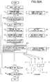
- Fig. 20A is a flow chart for explaining image processing in the third embodiment.
- the same reference numerals in Fig. 20A denote the same portions as in Figs. 2A and 17A, and a description thereof will be omitted.
- Fig. 20A shows a (one-pass) print algorithm for printing an image corresponding to the head width by one main scanning operation.
- a RAM 5 includes record history memories 5b (M1, M2, M3, and M4) respectively prepared for inks D1, D2, D3, and D4.
- step S20 initial values are set in the respective record history memories 5b.
- the initial values- in the respective record history memories 5b are time data each indicating the time required for the nozzle of each ink-jet head unit to move from the preliminary discharge position ("A" in Fig. 10A) in each main scanning operation to the print start position ("D" in Fig. 10A).
- This time data may be time data itself or any data, other than time data, which allows reference to the density change values in an ink density change characteristic table 4e (Fig. 9).
- target pixel selection processing 12 a target pixel to be processed is selected, and its density data CD is obtained.
- ink type distribution processing 13 an ink type distribution table 4b is referred to on the basis of the density value of the target pixel to determine an ink combination candidate for printing with the density of the target pixel.
- density change prediction processing 10 the degree of variation in ink density in actual printing operation with respect to the ideal density is predicted by referring to the ink density change characteristic table 4e, which is linearly approximated by the least squares method using experimental values, on the basis of the continuous non-discharge time data of the nozzles which are stored in the record history memories 5b for the respective nozzles.
- a density variation accompanying the ink combination selected by the ink type distribution processing 13 is calculated on the basis of the predicted density obtained by the density change prediction processing 10, and the ink combination is changed, as needed, thereby determining an optimal ink density combination, i.e., binary data d1, d2, d3,... indicating the discharging/non-discharging at the respective ink-jet head units, each having ink with different density from each other.
- step S21 M1, M2, M3,... of the record history memories 5b corresponding to the respective nozzles are updated on the basis of the binary data d1, d2, d3,... indicating the discharging/non-discharging at the nozzles, each having ink with different density from each other.
- time data indicating the time to the next ink discharge timing which is obtained from the relationship between the value in the carriage movement characteristic table 4f and the position of the current pixel, is added to the record history memory 5b corresponding to each nozzle determined as "non-discharging".
- no time data is added to the record history memory 5b corresponding to each nozzle determined as "discharging", and time data indicating the time to the next discharge timing is set in the memory 5b.
- the binary data d1, d2, d3,... indicating the discharging/non-discharging at the respective ink-jet head units, each having ink with different density, are determined in accordance with the density value of the target pixel.
- These binary data are respectively sent to the corresponding ink-jet head units.
- the head units are driven to perform printing.
- the processing from the target pixel selection processing 12 in Fig. 20A to the density change correction processing 14 is performed for all the pixels of one-line image data on the basis of the density values (CD) of the image.
- the history memories 5b are initialized in units of lines in step S20 to generate the binary data d1, d2, d3,... indicating the discharging/non-discharging of ink from the head units, each having ink with different density, in units of pixels.
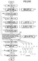
- Fig. 20B is a flow chart showing image processing in a modification of the third embodiment.
- the same reference numerals in Fig. 20B denote the same portions as in Fig. 20A, and a description thereof will be omitted.
- Density error calculation processing 15 is performed to calculate the difference between the CD value of the target pixel and the density that can be expressed by the ink combination determined by the density change correction processing 14 in accordance with the additive properties of the ink, i.e., the density (OD) determined in consideration of density change prediction.
- error diffusion processing 16 the difference (error) calculated by the density error calculation processing 15 is diffused to the neighboring pixels of the target pixel in the page memory in accordance with the distribution coefficients (Fig. 13).
- one pixel of interest (target pixel) is completely processed.
- the binary data d1, d2, d3,... indicating the discharging/non-discharging of ink from the respective head units, each having ink with different density in a color, are generated.
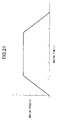
- Fig. 21 is a graph showing the movement characteristics of the carriage 20 (ink-jet head units 21) in the third embodiment with respect to a printing medium.
- the abscissa represents the moving time in the main scanning direction; and the ordinate represents the moving speed.
- Figs. 22A to 22C are views for explaining main scanning printing performed by the printer unit 7 in Fig. 4 and the ink discharging timing.
- Fig. 22A is a view showing the printing unit of the printer unit 7 when viewed from a side parallel to the recording surface of a printing medium 24.
- Fig. 22B is a plan view of the printing medium 24 set at the recording unit.
- the carriage 20 on which ink-jet head units 21-1 to 21-4 are mounted begins to move from the home position (not shown) in the direction indicated by an arrow S. While the ink-jet head unit 21-1 passes over an ink reservoir 33, the carriage 20 moves at a constant speed.
- the ink-jet head units 21-1 to 21-4 sequentially pass over the ink reservoir 33 in the order named and preliminary discharge ink to the ink reservoir 33 at a position A (the position of the ink reservoir 33). Printing operation is then performed in a length B - C.
- the moving direction of the carriage 20 is reversed, and the carriage 20 returns to the home position.
- the printing medium 24 is fed in the sub-scanning direction (F) by the width of an image printed by one main scanning operation to prepare for printing by the next main scanning operation.
- Fig. 22C is a graph showing the movement characteristics of each ink-jet head unit 21 mounted on the carriage 20 with respect to the printing medium 24 in main scanning operation.
- the abscissa represents the position of the carriage 20 in the main scanning direction; and the ordinate represents the time intervals of the discharge timings. Note that the position on the abscissa may be expressed in units of dots on the basis of the dot density (resolution) to facilitate reference in image processing.
- Reference symbol A denotes a preliminary discharge position
- reference H denotes a home position
- reference P1 denotes the first ink discharge position of the ink-jet head unit 21-1
- reference T1 denotes the discharge timing of the ink-jet head unit 21-1 at the position P1 on the printing medium 24
- references P2 to P4 denote the positions of the ink-jet head unit 21-1 when the ink-jet head units 21-2, 21-3, and 21-4 pass the preliminary discharge position A.
- Reference numerals T2, T3, and T4 therefore denote the discharge timings of the ink-jet head units 21-2 to 21-4 at the time when they pass the position P1.
- an ink density change caused when the ink-jet head unit 21-1 passes the position P1 can be obtained as follows. An ink density increase is obtained first by referring to Fig. 7 on the basis of the time required for the ink-jet head unit 21-1 to reach the position P1 from the preliminary discharge position A. The ink density change characteristic table 4e in Fig. 9 is then referred to.
- the number of dots corresponding to the distance is obtained on the basis of the print density, and the distance between the position A and the position P1 can be expressed on the basis of the number of dots.
- the time required for the ink-jet head unit 21-1 to reach the position P1 from the preliminary discharge position A can be obtained by adding the dot discharge timing intervals, in accordance with the number of dots between the position A and the position P1 in the movement characteristics graph shown in Fig. 22C.
- an ink density change caused when the ink-jet head unit 21-2 passes the position P1 may be obtained by referring to the ink density change characteristic table 4e in Fig. 9 on the basis of the time required for the ink-jet head unit 21-2 to reach the position P1 from the preliminary discharge position A.
- the ink-jet head unit 21-2 is spaced apart from the preceding ink-jet head unit 21-1 by the distance (P2 - P1).
- the time required for the ink-jet head unit 21-2 to reach the position P1 from the preliminary discharge position A can be obtained by referring to Fig. 22C in this manner in consideration of the distance (P2 - P1) to the preceding ink-jet head unit 21-1. This time is equal to the time required for the ink-jet head unit 21-1 to reach the position P2 from the preliminary discharge position A.
- the time required for the ink-jet head unit 21-3 to reach the position P1 from the preliminary discharge position A is equal to the time required for the ink-jet head unit 21-1 to reach the position P3 from the preliminary discharge position A.
- the time required for the ink-jet head unit 21-4 to reach the position P1 is equal to the time required for the ink-jet head unit 21-1 to reach the position P4.
- the initial values to be stored in the record history memories 5b for the first pixel of each line can be obtained in the above manner on the basis of these time values.
- the movement characteristics of the remaining ink-jet head units can be calculated by using the carriage movement characteristic table 4f for the ink-jet head unit 21-1 in consideration of the positions of the respective ink-jet head units relative to the position of the ink-jet head unit 21-1.
- the discharge timing of each ink-jet head unit at each point on the printing medium 24 can be controlled by making the position of each target pixel correspond to the printing position of each ink-jet head unit and referring to the carriage movement characteristic data in Fig. 22C.
- this timing interval prediction method By applying this timing interval prediction method to the image processing in Figs. 20A and 20B, density change prediction and correction with respect to non-discharging nozzles can be performed regardless of whether the carriage is moving at a constant speed, accelerating, or decelerating.
- the carriage 20 is moved to the home position H and stopped.
- the carriage motor 30 is rotated to accelerate the carriage 20.
- a timer (not shown) is started concurrently with the start of the movement of the carriage 20 to measure the intervals between pulse signals generated by the linear encoder 28 in synchronism with the movement of the carriage 20, thereby obtaining carriage movement characteristic data corresponding to the respective carriage positions.
- the obtained data are written in the work area of the RAM 5.
- This measurement is performed in the time interval between the instant at which the carriage 20 starts to run at a constant speed and the instant at which the carriage 20 decelerates and stops to complete one scanning operation. As a result, the carriage movement characteristic data shown in Fig. 22C is generated.
- Accurate carriage movement characteristic data can be obtained by repeating this measurement a plurality of number of times and obtaining the average of the resultant data.
- the carriage movement characteristic table 4f can be generated on the basis of this data.
- the carriage movement characteristic table 4f can be generated regardless of control on main scanning operation.
- Fig. 23 is a block diagram showing the functional arrangement of an ink-jet printing system according to the fourth embodiment of the present invention.
- the same reference numerals in Fig. 23 denote the same parts as in the drawings described above, and a description thereof will be omitted.
- the arrangement of a printer unit 7 including ink-jet heads and the like in the fourth embodiment is the same as that in Fig. 4, a description thereof will also be omitted.
- reference numeral 4c denotes a table group indicating ink density change characteristics with respect to the non-discharging time, which are referred to in multilevel gradation processing and ink type distribution processing.
- This table group includes a plurality of ink density change characteristic tables prepared according to humidity and temperature conditions.
- Reference numeral 9 denotes an image memory for storing image data input from an image input unit 1;
- numeral 410 denotes a bit plane memory for storing binarized image data;
- numeral 411 denotes a humidity sensor for measuring the environmental humidity around the printer unit 7; and
- numeral 412 denotes a temperature sensor for measuring the environmental temperature around the printer unit 7.
- ink-jet head units 21 of the printer unit 7 discharge ink from the nozzle arrays at a frequency of 10 kHz.
- 10,000 ink droplets are discharged from the nozzle array of each ink-jet head unit 21 with a 600-dpi pitch.
- a carriage 20 scans a short side of an A3 sheet in about 0.7 sec at a scanning speed of about 423.33 mm/sec.
- the density increase rate of each ink used in the fourth embodiment is proportional to the non-discharging time, and the slope of the density increase rate changes with temperature and humidity while the carriage 20 scans a short side (297 mm) of the A3 sheet.
- the "non-discharging time” is the time interval between the instant at which an ink droplet is discharged from one nozzle of the ink-jet head unit 21 and the instant at which the next ink droplet is discharged from this nozzle.
- Figs. 26A and 26B are graphs for explaining the data of the ink density change characteristic table 4c indicating the change rate of ink density with respect to the non-discharging time.
- Fig. 26A shows changes in ink density increase rate at a constant temperature of 30C° with changes in humidity from 10% to 70% at a rate of 10%.
- Fig. 26B shows changes in ink density increase rate at a constant humidity of 40% with changes in ambient temperature from 15C° to 35C° at a rate of 5C°.
- each ink-jet head unit 21 An increase in ink density during scanning operation of each ink-jet head unit 21 results from evaporation of the ink solvent at each nozzle tip.
- the ink whose density has increased at a nozzle tip is discharged as an ink droplet in one ink discharging operation, fresh ink is charged into the nozzle tip.
- the ink density at the nozzle tip returns to the prescribed (original) density before the increase in density.
- the printer unit 7 was carried into an environmental test room (not shown) in which temperature and humidity can be controlled.
- a test pattern for density increase rate measurement in Fig. 27B was printed with a specific ink while the humidity and temperature were kept constant.
- a densitometer (not shown)
- Ink density change characteristic tables like those shown in Figs. 26A and 268 can be obtained by calculating ink density increase rates on the basis of the above experimental results, linearly approximating the density increase rates at the respective points by the least squares method, and classifying the data obtained at a constant temperature or humidity as characteristic tables for the respective types of ink.
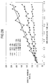
- Fig. 28 shows measured ink density increase rates of an ink having a transmission density of 3.2 D with respect to the non-discharging time under environments of a temperature of 30C° and a humidity of 15%, a temperature of 15C° and a humidity of 15%, and a temperature of 30C° and a humidity of 80%, and an example of linear approximation curves obtained by the least squares method.
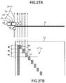
- Figs. 27A and 27B schematically show the main scanning unit of the printer unit 7 in Fig. 4.
- Fig. 27A is a side view of a printing section.
- Fig. 27B is a plan view of the printing medium 24 set at the printing section.
- reference numeral 20 denotes a carriage;
- numerals 21-1 to 21-4 denotes ink-jet head units;
- numeral 33 denotes an ink reservoir for preliminary discharging.
- the carriage 20 moves at a constant speed in the direction indicated by an arrow S.
- Each of the ink-jet head units 21-1 to 21-4 can preliminary discharge ink to the ink reservoir 33 at a position A where each of the ink-jet head units passes over the ink reservoir 33.
- the discharge frequency of the ink-jet head unit 21 is 10 kHz, and the print density in the main scanning direction is 600 dpi.
- a length B - C corresponds to 200 dots
- a length C - D corresponds to 200 dots.
- a convey motor 26 in Fig. 4 is driven to convey a printing medium 24 in the direction indicated by an arrow F and stop it such that the ink-jet head unit 21 comes to the sub-scanning position corresponding to a band W1 in Fig. 27B.
- the width of the band W1 corresponds to the length of an array of nozzles of each ink-jet head unit.
- the moving speed of the carriage 20 at which ink is discharged at a print density of 600 dpi and a discharge frequency of 10 kHz is 423.3 mm/sec. Note that the carriage 20 moves on the printing medium 24 at a constant speed while printing operation.
- the carriage 20 starts from the home position (not shown), and the ink-jet head unit 21-1 preliminary discharges ink to the ink reservoir 33 at the position A.
- the position B ink droplets are simultaneously discharged from all the nozzles of the ink-jet head unit 21-1.
- the main scanning operation is stopped.
- the carriage 20 then returns to the home position, and the first scanning operation is complete without feeding the printing medium 24.
- the ink-jet head unit 21-1 performs preliminary discharging at the position A. Then, ink droplets are simultaneously discharged from all the nozzles onto a portion shifted from the position B to the right by one dot. Thereafter, ink droplets are simultaneously discharged from all the nozzles onto a portion shifted from the position C to the right by one dot, and the main scanning operation is stopped. The carriage 20 then returns to the home position, and the second scanning operation is complete without feeding the printing medium 24.
- the printing medium 24 is fed in the direction indicated by the arrow F by one band.
- the band W2 is printed at the width B - C and a width E - F.
- the width B - D corresponds to 200 dots as in the case with the band W1
- the width E - F corresponds to 200 dots
- a width B - E corresponds to 500 dots.
- the ink-jet head unit 21-1 performs preliminary discharging at the position A.
- the position B ink droplets are simultaneously discharged from all the nozzles.
- the main scanning operation is stopped. The carriage 20 then returns to the home position, and the first scanning operation is complete without feeding the printing medium 24.
- preliminary discharging is performed at the position A, and ink droplets are simultaneously discharged from all the nozzles of the ink-jet head unit 21-1 onto a portion shifted from the position B to the right by one dot. Thereafter, ink droplets are simultaneously discharged from all the nozzles onto a portion shifted from the position E to the right by one dot.
- the main scanning operation is then stopped.
- the carriage 20 returns to the home position (not shown). The second scanning operation is complete without feeding the printing medium 24.
- the printing medium 24 is fed in the direction indicated by the arrow F by one band by the convey roller (not shown).
- the band W3 is printed at the length B - C and a length G - H.
- the length B - C corresponds to 200 dots as in the case with the band W1
- the length G - H corresponds to 200 dots
- a length B - G corresponds to 800 dots.
- the test pattern shown in Fig. 27B is printed.
- the interval of a pattern 55 printed on the band W1 corresponds to 200 dots, which correspond to a non-discharging time of 0.2 sec.
- the interval of a pattern 55 printed on the band W1 corresponds to 200 dots, which correspond to a non-discharging time of 0.02 sec.
- the interval of a pattern 56 printed on the band W2 corresponds to 500 dots, which correspond to a non-discharging time of 0.05 sec.
- the interval of a pattern 57 printed on the band W3 corresponds to 800 dots, which correspond to a non-discharging of 0.08 sec.
- Fig. 28 shows the result obtained by calculating ink density increase rates on the basis of the data obtained by printing the above patterns using an ink having a transmission density of 0.24 D under environments of a temperature of 30C° and a humidity of 15%, a temperature of 15C° and a humidity of 15%, and a temperature of 30C° and a humidity of 80%.
- the minimum interval of printed patterns is set to 200 dots to allow measurement with a densitometer having a large measurement spot. If, however, a densitometer having a small measurement spot or slit type measurement spot can be used, this print width may be reduced to, e.g., 10 dots.
- Figs. 24A and 24B are flow charts for explaining the flow of processing in the image processing unit 6 in the fourth embodiment of the present invention.
- the same reference numerals in Figs. 24A and 24B denote the same portions as in Figs. 2A, 2B, 17A, 17B, 20A, and 20B, and a detailed description thereof will be omitted.
- Figs. 24A and 24B show an example of how image processing is performed by a one-pass print algorithm for completing printing of an image corresponding to the head width (e.g., 256 nozzles) of each ink-jet head unit 21 by scanning the carriage 20 only once.
- the number of record history memories 5b required for this image processing is determined by the types of ink used for printing and the print algorithm. Note that the record history memories 5b are prepared in a RAM 5.
- an image signal CV input from the image input unit 1 is converted into a signal CD indicating a density by using a gamma correction conversion table 4a, and the signal is stored in the image memory 9.
- initial values are set in the record history memories 5b.
- the initial value in each record history memory 5b is time data indicating the time required for the nozzle of the corresponding head unit to move from the preliminary discharge position (corresponding to the position A in Fig. 27A) to the print start position (corresponding to "B" in Fig. 27A) for the image.
- target pixel selection processing 12 each pixel to be processed is sequentially selected from the image memory 9, and density data CD of each pixel is obtained.
- ink type distribution processing 13 an ink combination for expressing the density CD of the target pixel is selected by referring to an ink type distribution table 4b on the basis of the CD value of the target pixel.
- ink density change characteristic tables are stored in correspondence with combinations of humidities and temperatures within the environmental range in which the printer unit 7 in this embodiment can operate.
- a total of 48 types of ink density change characteristic tables are prepared, which are linearly approximated from experimental values by the least squares method while the humidity range of 20% to 90% is divided in increments of 10% and the environmental temperature range of 0C° to 50C° is divided in increments of 10C°.
- an ink density change characteristic table indicating an envirornent closet to the environment in which the printer unit 7 is installed is selected from the ink density change characteristic table group 4c on the basis of the values of the environmental humidity and temperature around the ink-jet head unit 21 which are detected by the humidity sensor 411 and the temperature sensor 412. Subsequently, the selected ink density change characteristic table is referred to on the basis of the non-discharging time data stored in the record history memory 5b for each nozzle, thereby predicting the degree of variation in print density based ink from the corresponding nozzle relative to the ideal density.
- a substantial print density variation caused by the ink combination selected by the ink type distribution processing 13 is calculated on the basis of the density predicted by the density change prediction processing 10, and the ink combination is changed, as needed, to determine an optimal ink density combination, i.e., the binary data d1, d2, d3, and d4 indicating the discharging/non-discharging of ink from the nozzles of the respective ink-jet head units.
- the record history memories 5b corresponding to the respective nozzles are updated on the basis of the binary data d1, d2, d3, and d4 indicating the discharging/non-discharging of ink from the respective nozzles.
- a target pixel is selected by using target pixel selection information, a counter that is incremented by one at the end of processing for each pixel, and the like.
- density change prediction is performed on the basis of the value of the record history memory 5b to predict that the ink density increases by an amount corresponding to the time intervals of ink discharge timings of each nozzle. For this reason, time data indicating the time to the next ink discharge timing is added to the data of the record history memory 5b corresponding to each nozzle determined as a non-discharging nozzle.
- time data indicating the time to the next ink discharge timing is set in the record history memory 5b corresponding to each nozzle determined as a discharging nozzle without adding it to the data of the memory. That is, the contents of each record history memory 5b represent the continuous non-discharging time of the corresponding nozzle.
- the binary data d1, d2, d3, and d4 are transferred first to a buffer memory 430 and then stored in the bit plane memory 410.
- the binary data sent in units of bits is bit-shifted every time it is sent. When these data are stored in a specified amount, the data are transferred to the bit plane memory 410.
- bit planes consisting of the binary data d1, d2, d3, and d4 are formed in different address areas in the bit plane memory 410.
- Fig. 24B is a flow chart showing a modification of the flow of processing in the fourth embodiment, in which the following processing is performed in addition to the processing described above.
- a density error is obtained, and density interpolation is performed by, for example, diffusing the error to neighboring pixels. Since the processing up to step S12 is the same as in Fig. 24A, a description thereof will be omitted.
- Density error calculation processing 15 is performed to calculate the difference between the CD value of the target pixel and the density that can be expressed by the ink combination determined by the density change correction processing 14, i.e., the density determined in consideration of density change prediction.
- error diffusion processing 16 the difference calculated by the density error calculation processing 15 is diffused to the pixels around the target pixel in the page memory in accordance with the distribution coefficients shown in Fig. 13. In this manner, the processing for the target pixel is complete.
- ink density change characteristic tables are prepared in correspondence with combinations of humidities set in increments of 10% and temperatures set in increments of 10°C.
- the standard for the classification of ink density change characteristic tables in the present invention is not limited to this, and a standard may be arbitrarily prepared in accordance with the types of ink to be used within the range in which gradation level correction can be properly performed.
- the number of ink density change characteristic tables to be prepared may be equal to the number of the types of ink.
- ink density change characteristic tables equal in number to the groups may be prepared.
- a plurality of ink density change characteristic tables are prepared such that humidities are set in increments of 10% and temperatures are set in increments of 10°C under the set humidities.
- the values in ink density change characteristic tables 4c can be linearly approximated from experimental values by the least squares method, as shown in Figs. 26A and 26B.
- density change characteristics may be stored in a storage medium 4 in correspondence with each type of ink corresponding to each combination of humidities and temperatures.
- an ink density change characteristic table 4c may be generated on the basis of the environmental humidities and temperatures detected by the humidity sensor 411 and the temperature sensor 412. In density change prediction processing, this table may be referred to.
- Figs. 25A and 25B are flow charts showing the flow of processing in an image processing unit 6 according to the sixth embodiment of the present invention.
- the same reference numerals in Figs. 25A and 25B denote the same portions as in the drawings described above, and a description thereof will be omitted.
- gamma correction processing 11 converts an image signal CV input through an image input unit 1 into a signal CD representing a density by using a gamma correction conversion table 4a, and stores the signal in an image memory 9.
- ink density change characteristic table generation processing in step S31 ink density change characteristic tables are generated from data representing the density change characteristics of each type of ink at the environmental humidities and temperatures (not shown) stored in the storage medium 4 on the basis of the state quantities of ambient humidities and temperatures around the printer unit 7 which are detected by the humidity sensor 411 and the temperature sensor 412. Since the subsequent processing is the same as that in the flow of processing shown in Fig. 24A, a description thereof will be omitted.
- Fig. 25B shows a modification of the sixth embodiment.
- density error calculation processing 15 and error diffusion processing 16 are also performed, and the pixel values around the target pixel in the image memory 9 are updated on the basis of the resultant errors.
- the density error correction method uses the error diffusion method as area gradation processing.
- gradation processing is not limited to error diffusion.
- other area gradation processing methods such as the density pattern method or the dither method may be used.
- a method of determining ink types and printing an image by using the density pattern method according to the seventh embodiment of the present invention will be described below, together with a density error correction method of distributing a density error caused in the method of this embodiment. Since the arrangement of an ink-jet printing apparatus according to the seventh embodiment is the same as that of the above embodiment, a description thereof will be omitted.
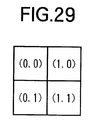
- each pixel of an image is expressed by a 2 x 2 dot density pattern (Fig. 29).
- the present invention is not limited to this.
- each pixel may have a matrix size of 4 x 4 dots.
- dots constituting the density pattern are printed by superimposing four types of ink D1, D2, D3, and D4, each having different density from each other in a color as in the above embodiment.
- 8-bit density levels that can be expressed by dots, and superimposed transmission densities are the same as those in Fig. 6 described above.
- the positions of the respective dots in the 2 x 2 density pattern i.e., the upper left, upper right, lower left, and lower right positions, are respectively defined as (0, 0), (1, 0), (0, 1), and (1, 1).
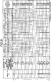
- Fig. 30 shows an example of how a density pattern is formed by sequentially assigning dots to the respective coordinate positions in matrices according to the gradation expression of density data shown in Fig. 6 (density data increases in increments of "17").
- density data increases in increments of "17"
- the density value of each dot in the matrices in Fig. 30 corresponds to 8-bit density data expressed by one dot in Fig. 6.
- the value blow each matrix indicates the average density (print density value) of the matrix.
- Fig. 31 shows the contents of an ink type distribution table 4b for forming the density pattern shown in Fig. 30 and, more specifically, an ink type distribution table representing the discharging/non-discharging of the inks D1, D2, D3, and D4 of the respective dots of each 2 x 2 density pattern corresponding to an image signal (density data), the transmission densities of the inks D1, D2, D3, and P4, and the transmission densities of the respective matrices obtained by superimposing the combinations of ink in the ink type distribution table.
- an ink type distribution table representing the discharging/non-discharging of the inks D1, D2, D3, and D4 of the respective dots of each 2 x 2 density pattern corresponding to an image signal (density data), the transmission densities of the inks D1, D2, D3, and P4, and the transmission densities of the respective matrices obtained by superimposing the combinations of ink in the ink type distribution table.
- ink type distribution processing 13 is performed for a target pixel on the basis of the above arrangement by using the ink type distribution table 4b in Fig. 31.
- an ink density change is predicted in accordance with the non-discharging time of each ink by referring to an ink density change characteristic table 4e (density change prediction processing 10), and correction processing for determining each ink type with the predicted density increase is performed (density change correction processing 14).
- data to be output to two nozzles is determined for one pixel.
- this embodiment differs from the previous embodiments.
- the error between the density value determined by the density change correction processing and the actual print density is further obtained to perform density correction for the corresponding pixel of the image data. This processing will be describe next.
- the density data of the pixel selected by target pixel selection processing 12 is "42.5".
- Ink types used to print this pixel are selected by the same method as in the above embodiment on the basis of the respective pixel values of the matrix and the ink type distribution table 4b (ink type distribution processing 13).
- An ideal ink combination is then determined by referring to the ink density change characteristic table 4e in consideration of the density increase of each ink based on the continuous non-discharging interval of each nozzle (density change correction processing 14).
- the error between the density obtained by the ink combination and the target density data "51" is calculated (density error calculation processing 15), and an error ⁇ E is distributed to the pixel data "51" at the position (1, 0). With this processing, the target pixel density at the position (1, 0) becomes "51 + ⁇ E0" (density error diffusion processing 16).
- an optimal ink combination for expressing the pixel density "51 + ⁇ E0" at the position (1, 0) is selected in consideration of the density increase of each ink based on the non-discharging interval of each nozzle.
- the error between the density value obtained by the ink combination and the target density value "51 + ⁇ E0" is calculated, and an error ⁇ E1 is distributed to the pixel "34" at the position (0, 1). With this processing, the density value of the pixel at the position (0, 1) becomes "34 + ⁇ E1.
- the nozzle of the print head which is used to print the dot at the position (0, 1) is located immediately below the nozzle that is used to print the dots at the positions (0, 0) and (1, 0). That is, the history counter used for referring to the non-discharging of this nozzle is the one corresponding to the nozzle.
- An optimal ink combination for expressing the density value "34 + ⁇ E1" is determined on the basis of the non-discharging interval of each nozzle in consideration of the ink density increase at the nozzle in the same manner as described above except for the history counter to be referred to.
- the processing from the ink type distribution processing 13 to the error diffusion processing 16 must be repeated four times for one target pixel data.
- the errors are distributed in the order of the positions (1, 0), (0, 1), and (1, 1).
- error distribution is not limited to this, and errors may be distributed to unprocessed dots on the basis of some appropriate distribution coefficients.
- the error ⁇ E0 caused at the position (0, 0) may be distributed to the positions (1, 0), (0, 1), and (1, 1) 1/3 the error at a time; the error ⁇ E1 caused at the position (1, 0), to the positions (0, 1) and (1, 1) 1/2 the error at a time; and the error ⁇ E2 caused at the position (0, 1), to the position (1, 1).
- the size of the density pattern, ink combinations, and the like are not limited to those presented in the embodiment described above.
- the density increase rate of each ink is not proportional to the non-discharging time, for example, if the density increase of each ink reaches its limit after a lapse of a predetermined period of time, the corresponding relationship may be reflected in the ink density change characteristic table 4e in Fig. 9.
- the ink density change characteristic tables have been described. However, such tables are not limited to density increases. That is, any curves that represent ink density increase characteristics can be used.
- the storage data can be written by arbitrary characteristic data.
- the density change characteristic tables in this embodiment are not limited to ink. That is, any tables that represent density changes of print results obtained by using sublimation type films, thermal transfer tapes, heat-sensitive sheets, and the like can be used.
- density change tables in this embodiment are replaced with the relationship between print duty and density increase, an increase in print density can be predicted, and corresponding correction can be performed. If, for example, record history information is converted into a cumulative heat amount in a past predetermined interval, a density increase can be predicted.
- the present invention may be applied to either a system constituted by a plurality of equipments (e.g., a host computer, an interface device, a reader, a printer, and the like), or an apparatus consisting of a single equipment (e.g., a copying machine, a facsimile apparatus, or the like).
- equipments e.g., a host computer, an interface device, a reader, a printer, and the like
- an apparatus consisting of a single equipment e.g., a copying machine, a facsimile apparatus, or the like.
- the present invention has been described as the scheme which has a means (e.g., an electricity-to-heat converter or laser light) for generating heat energy as energy used to discharge an ink, and changes the state of an ink by using the heat energy.
- a means e.g., an electricity-to-heat converter or laser light
- the present invention is not limited to this and can be applied to a scheme using a piezoelectric element as a means for discharging an ink. According to this scheme, high-density, high-definition printing operation can be realized.
- a satisfactory effect can be obtained when the on-demand type apparatus is employed because of the structure arranged in such a manner that one or more drive signals, which rapidly raise the temperature of an electrothermal converter disposed to face a sheet or a channel which holds the fluid (ink) to a level higher than levels at which film boiling takes place are applied to the electrothermal converter in accordance with print information so as to generate heat energy in the electrothermal converter and to cause the heat effecting surface of the print head to take place film boiling so that bubbles can be formed in the fluid (ink) to correspond to the one or more drive signals.
- the enlargement/contraction of the bubble will cause the fluid (ink) to be discharged through an orifice so that one or more droplets are formed.
- a pulse shape drive signal is employed, the bubble can be enlarged/contracted immediately and properly, causing a further preferred effect to be obtained because the fluid (ink) can be discharged while revealing excellent responsibility.
- a structure having an arrangement that the heat effecting surface is disposed in a bent region and disclosed in U.S. Patent No. 4,558,333 or 4,459,600 may be employed.
- the following structures may be employed: a structure having an arrangement that a common slit is formed to serve as a discharge section of a plurality of electrothermal converters and disclosed in Japanese Patent Laid-Open No. 59-123670; and a structure disclosed in Japanese Patent Laid-Open No. 59-138461 in which an opening for absorbing pressure waves of heat energy is disposed to correspond to the discharge section.
- a print head of the full line type having a length corresponding to the maximum width of a printing medium on which information can be printed by the printing apparatus
- either the construction which satisfies its length by a combination of a plurality of print heads as disclosed in the above specifications or the construction as a single full line type print head which has integrally been formed can be used.
- the invention is effective for a print head of the exchangeable chip type which enables electrical connection to the printer apparatus main body or supply of ink from the main body by being mounted onto the printer apparatus main body, or for use of a print head of the cartridge type provided integrally on the print head itself.
- the printer apparatus of each embodiment described above additionally employ a print head restoring means and an auxiliary means, because the printing operation can be further stabilized. More specifically, it is preferable to employ a print head capping means, a cleaning means, a pressurizing or suction means, an electrothermal converter, an another heating element or a preliminary heating means constituted by combining them, and a preliminary discharging mode of performing a discharging operation independently of a printing operation in order to perform stable printing.
- a fluid ink is employed in the aforesaid embodiment of the present invention
- an ink which is solidified at the room temperature or lower and as well as softened at the room temperature an ink in the form of a fluid at the room temperature, or an ink which is formed into a fluid when the print signal is supplied may be employed because the aforesaid ink-jet method is ordinarily arranged in such a manner that the temperature of ink is controlled in a range from 30C° or higher to 70C° or lower so as to make the viscosity of the ink to be included in a stable discharge range.
- an ink which is solidified when it is caused to stand, and liquified when heat energy is supplied in accordance with a print signal can be adapted to the present invention to positively prevent a temperature rise caused by heat energy by utilizing the temperature rise as energy of state transition from the solid state to the liquid state or to prevent ink evaporation.
- an ink which is liquified when heat energy is supplied in accordance with a print signal so as to be discharged in the form of fluid ink, or an ink which is liquified only after heat energy is supplied, e.g., an ink which starts to solidify when it reaches a printing medium, can be adapted to the present invention. It is the most preferred way for the ink to be adapted to the aforesaid film boiling method.
- the objects of the present invention are also achieved by supplying a storage medium, which records a program code of a software program that can realize the functions of the above-mentioned embodiments to the system or apparatus, and reading out and executing the program code stored in the storage medium by a computer (or a CPU or MPU) of the system or apparatus.
- the program code itself read out from the storage medium realizes the functions of the above-mentioned embodiments, and the storage medium which stores the program code constitutes the present invention.
- the storage medium for supplying the program code for example, a floppy disk, hard disk, optical disk, magneto-optical disk, CD-ROM, CD-R, magnetic tape, nonvolatile memory card, ROM, and the like may be used.
- the functions of the above-mentioned embodiments may be realized not only by executing the readout program code by the computer but also by some or all of actual processing operations executed by an OS (operating system) traveling on the computer on the basis of an instruction of the program code.
- OS operating system
- the functions of the above-mentioned embodiments may be realized by some or all of actual processing operations executed by a CPU or the like arranged in a function extension board or a function extension unit, which is inserted in or connected to the computer, after the program code read out from the storage medium is written in a memory of the extension board or unit.
- an excessive density increase at the start of printing of an image can be suppressed by changing the combination of types of ink, each type of ink has different density from each other and is to be substantially printed on the same portion, on the basis of the density change characteristics of the respective inks.
- high-resolution printing with excellent gradation characteristics can be provided even with changes in ink densities by correcting a portion, which cannot be properly corrected by only changing the ink combination, by image processing such as error diffusion.
- each embodiment described above has exemplified the ink-jet printing apparatus, but the present invention can be applied to other types of printing apparatuses.
- a printer using a heating head e.g., a sublimation printer
- continuous printing operation raises the temperature of the head.
- the density of a printed image increases. If the density change table described in the present invention is replaced with the relationship between print duty and density increase, an increase in the density of an image to be printed can be predicted, and corresponding correction can be performed.
- each embodiment described above has exemplified the ink-jet scheme using heat.
- the present invention is not limited to this.
- the present invention can be applied to an ink-jet scheme using piezoelectric elements.
- parameters such as variations in print density due to changes in quality of heat-sensitive sheets, ink ribbons, cartridge films for a sublimation type printer, and the like are input to density change tables, the tables can be corrected.
- the present invention can be implemented by a computer program operating on a computer.
- the computer program may also be obtained in electronic form for example by downloading the code over a network such as the Internet.
- a signal carrying processor implementable instructions for controlling a processor to carry out the method as hereinbefore described.
Landscapes
- Engineering & Computer Science (AREA)
- Physics & Mathematics (AREA)
- Multimedia (AREA)
- Signal Processing (AREA)
- General Physics & Mathematics (AREA)
- Mathematical Physics (AREA)
- General Engineering & Computer Science (AREA)
- Theoretical Computer Science (AREA)
- Discrete Mathematics (AREA)
- Ink Jet (AREA)
- Particle Formation And Scattering Control In Inkjet Printers (AREA)
- Fax Reproducing Arrangements (AREA)
Applications Claiming Priority (4)
| Application Number | Priority Date | Filing Date | Title |
|---|---|---|---|
| JP5979398 | 1998-03-11 | ||
| JP05979398 | 1998-03-11 | ||
| JP05887699A JP4018286B2 (ja) | 1998-03-11 | 1999-03-05 | インクジェット記録方法及び装置及び記録システム |
| JP05887699 | 1999-03-05 |
Publications (2)
| Publication Number | Publication Date |
|---|---|
| EP0942585A2 true EP0942585A2 (de) | 1999-09-15 |
| EP0942585A3 EP0942585A3 (de) | 2000-10-11 |
Family
ID=26399894
Family Applications (1)
| Application Number | Title | Priority Date | Filing Date |
|---|---|---|---|
| EP99301829A Withdrawn EP0942585A3 (de) | 1998-03-11 | 1999-03-11 | Bildverarbeitungsverfahren und -Gerät und Aufzeichnungsgerät |
Country Status (3)
| Country | Link |
|---|---|
| US (1) | US6439683B1 (de) |
| EP (1) | EP0942585A3 (de) |
| JP (1) | JP4018286B2 (de) |
Cited By (2)
| Publication number | Priority date | Publication date | Assignee | Title |
|---|---|---|---|---|
| EP0970814A3 (de) * | 1998-06-29 | 2001-01-10 | Canon Kabushiki Kaisha | Druckverfahren und Vorrichtung |
| US7118189B2 (en) | 2004-05-28 | 2006-10-10 | Videojet Technologies Inc. | Autopurge printing system |
Families Citing this family (39)
| Publication number | Priority date | Publication date | Assignee | Title |
|---|---|---|---|---|
| JP2001310535A (ja) * | 2000-04-28 | 2001-11-06 | Canon Inc | 記録装置、および記録ヘッドの濃度むら補正方法 |
| US7198347B2 (en) * | 2000-05-30 | 2007-04-03 | Seiko Epson Corporation | Adjustment of shift of dot position of printer |
| US20020149785A1 (en) * | 2001-03-30 | 2002-10-17 | Chia-Lin Chu | Automatic printer color correction based on characterization data of a color ink cartridge |
| EP1407426A1 (de) * | 2001-07-05 | 2004-04-14 | EM Microelectronic-Marin SA | Verfahren zum schlüssellosen entriegeln einer zugangstür zu einem abgeschlossenen bereich |
| JP4916059B2 (ja) * | 2001-07-31 | 2012-04-11 | キヤノン株式会社 | 画像処理装置 |
| JP2003066774A (ja) * | 2001-08-24 | 2003-03-05 | Canon Inc | 画像形成装置及び自己診断システム |
| JP2003154629A (ja) * | 2001-11-22 | 2003-05-27 | Ryobi Ltd | 両面印刷機の印刷濃度管理装置 |
| JP2004195964A (ja) * | 2002-12-02 | 2004-07-15 | Seiko Epson Corp | 印刷装置、コンピュータプログラム、コンピュータシステム、印刷方法、及び、印刷物の製造方法 |
| US20040253281A1 (en) * | 2003-06-12 | 2004-12-16 | Atrium Medical Corp. | Therapeutic markings applied to tissue |
| US7364263B2 (en) * | 2004-01-21 | 2008-04-29 | Silverbrook Research Pty Ltd | Removable inkjet printer cartridge |
| US7645025B2 (en) * | 2004-01-21 | 2010-01-12 | Silverbrook Research Pty Ltd | Inkjet printer cartridge with two printhead integrated circuits |
| US7097291B2 (en) | 2004-01-21 | 2006-08-29 | Silverbrook Research Pty Ltd | Inkjet printer cartridge with ink refill port having multiple ink couplings |
| US7425050B2 (en) * | 2004-01-21 | 2008-09-16 | Silverbrook Research Pty Ltd | Method for facilitating maintenance of an inkjet printer having a pagewidth printhead |
| US7441865B2 (en) | 2004-01-21 | 2008-10-28 | Silverbrook Research Pty Ltd | Printhead chip having longitudinal ink supply channels |
| US7374355B2 (en) * | 2004-01-21 | 2008-05-20 | Silverbrook Research Pty Ltd | Inkjet printer cradle for receiving a pagewidth printhead cartridge |
| US7303255B2 (en) | 2004-01-21 | 2007-12-04 | Silverbrook Research Pty Ltd | Inkjet printer cartridge with a compressed air port |
| US7328985B2 (en) * | 2004-01-21 | 2008-02-12 | Silverbrook Research Pty Ltd | Inkjet printer cartridge refill dispenser with security mechanism |
| US20050157112A1 (en) | 2004-01-21 | 2005-07-21 | Silverbrook Research Pty Ltd | Inkjet printer cradle with shaped recess for receiving a printer cartridge |
| US7469989B2 (en) * | 2004-01-21 | 2008-12-30 | Silverbrook Research Pty Ltd | Printhead chip having longitudinal ink supply channels interrupted by transverse bridges |
| US7731327B2 (en) | 2004-01-21 | 2010-06-08 | Silverbrook Research Pty Ltd | Desktop printer with cartridge incorporating printhead integrated circuit |
| US7448734B2 (en) | 2004-01-21 | 2008-11-11 | Silverbrook Research Pty Ltd | Inkjet printer cartridge with pagewidth printhead |
| US20050251152A1 (en) * | 2004-05-05 | 2005-11-10 | Atrium Medical Corp. | Illuminated medicated ink marker |
| US20060170730A1 (en) * | 2004-12-15 | 2006-08-03 | Rogers Robert E | Print head system minimizing stitch error |
| KR100622368B1 (ko) * | 2005-06-10 | 2006-09-13 | 삼성전자주식회사 | 노즐 에러 보상 방법 및 이 방법이 적용되는 화상형성장치 |
| JP4656125B2 (ja) * | 2007-11-12 | 2011-03-23 | セイコーエプソン株式会社 | インクジェット式記録装置 |
| JP2010201693A (ja) * | 2009-03-02 | 2010-09-16 | Mitsubishi Electric Corp | サーマルヘッド駆動方法および印画装置 |
| JP5152222B2 (ja) * | 2010-02-26 | 2013-02-27 | ブラザー工業株式会社 | 画像データ処理装置、液体吐出装置及びプログラム |
| US8693051B2 (en) * | 2010-09-24 | 2014-04-08 | Carestream Health, Inc. | High density ink-jet printing on a transparency |
| US8699107B2 (en) | 2010-11-23 | 2014-04-15 | Carestream Health, Inc. | High density ink-jet printing on a transparency in a cielab colorspace |
| US9056485B2 (en) | 2010-11-23 | 2015-06-16 | Carestream Health, Inc. | Color medical imaging on film |
| JP6029311B2 (ja) | 2011-05-10 | 2016-11-24 | キヤノン株式会社 | 画像処理装置および画像処理方法 |
| JP5975717B2 (ja) | 2011-05-10 | 2016-08-23 | キヤノン株式会社 | 画像処理方法および画像処理装置 |
| JP6315913B2 (ja) * | 2013-07-11 | 2018-04-25 | キヤノン株式会社 | インクジェット記録装置および検査パターン記録方法 |
| US9162509B1 (en) * | 2014-03-31 | 2015-10-20 | Xerox Corporation | System for detecting inoperative inkjets in printheads ejecting clear ink using thermal substrates |
| US9168737B1 (en) * | 2015-01-29 | 2015-10-27 | Funai Electric Co., Ltd. | System and method for ejecting adjustable amounts of ink |
| WO2016162092A1 (en) * | 2015-04-10 | 2016-10-13 | Hewlett-Packard Indigo B.V. | Selecting colorant amount for printing |
| JP6566720B2 (ja) * | 2015-05-25 | 2019-08-28 | キヤノン株式会社 | 画像処理装置および画像処理方法 |
| JP2018118382A (ja) * | 2017-01-23 | 2018-08-02 | セイコーエプソン株式会社 | 画像処理方法、画像処理装置および印刷システム |
| US10554860B2 (en) * | 2018-07-09 | 2020-02-04 | Toshiba Tec Kabushiki Kaisha | Image forming apparatus, test image, and output density adjustment method of image forming apparatus |
Citations (2)
| Publication number | Priority date | Publication date | Assignee | Title |
|---|---|---|---|---|
| EP0606022A1 (de) | 1993-01-08 | 1994-07-13 | Canon Kabushiki Kaisha | Aufzeichnungsverfahren zur Gradationsaufzeichnung mit hell- und dunkelfarbigen Tinten und Gerät dafür |
| EP0707966A2 (de) | 1990-10-04 | 1996-04-24 | Canon Kabushiki Kaisha | Bildaufzeichnungsgerät mit Aufzeichnungskopf |
Family Cites Families (15)
| Publication number | Priority date | Publication date | Assignee | Title |
|---|---|---|---|---|
| CA1127227A (en) | 1977-10-03 | 1982-07-06 | Ichiro Endo | Liquid jet recording process and apparatus therefor |
| US4330787A (en) | 1978-10-31 | 1982-05-18 | Canon Kabushiki Kaisha | Liquid jet recording device |
| US4345262A (en) | 1979-02-19 | 1982-08-17 | Canon Kabushiki Kaisha | Ink jet recording method |
| US4463359A (en) | 1979-04-02 | 1984-07-31 | Canon Kabushiki Kaisha | Droplet generating method and apparatus thereof |
| US4313124A (en) | 1979-05-18 | 1982-01-26 | Canon Kabushiki Kaisha | Liquid jet recording process and liquid jet recording head |
| US4558333A (en) | 1981-07-09 | 1985-12-10 | Canon Kabushiki Kaisha | Liquid jet recording head |
| JPS59123670A (ja) | 1982-12-28 | 1984-07-17 | Canon Inc | インクジエツトヘツド |
| JPS59138461A (ja) | 1983-01-28 | 1984-08-08 | Canon Inc | 液体噴射記録装置 |
| US4635078A (en) * | 1983-04-28 | 1987-01-06 | Canon Kabushiki Kaisha | Intermediate gradient image producing method |
| JPS6125365A (ja) * | 1984-07-13 | 1986-02-04 | Canon Inc | 中間調画像形成方法 |
| US5617123A (en) | 1987-05-20 | 1997-04-01 | Canon Kabushiki Kaisha | Image processing method utilizing multiple binarizing and recording agent depositing steps |
| US4855753A (en) * | 1987-06-19 | 1989-08-08 | Canon Kabushiki Kaisha | Method of ink jet recording and ink jet recording apparatus |
| US5111302A (en) * | 1988-12-02 | 1992-05-05 | Hewlett-Packard Company | Method and system for enhancing the quality of both color and black and white images produced by ink jet and electrophotographic printers |
| DE69524651T2 (de) | 1994-01-27 | 2002-06-13 | Hewlett-Packard Co.(A Delaware Corporation), Palo Alto | Drucksystem und -methode |
| US6142599A (en) | 1995-06-29 | 2000-11-07 | Canon Kabushiki Kaisha | Method for ink-jet recording and an ink-jet recording apparatus |
-
1999
- 1999-03-05 JP JP05887699A patent/JP4018286B2/ja not_active Expired - Fee Related
- 1999-03-10 US US09/265,589 patent/US6439683B1/en not_active Expired - Lifetime
- 1999-03-11 EP EP99301829A patent/EP0942585A3/de not_active Withdrawn
Patent Citations (2)
| Publication number | Priority date | Publication date | Assignee | Title |
|---|---|---|---|---|
| EP0707966A2 (de) | 1990-10-04 | 1996-04-24 | Canon Kabushiki Kaisha | Bildaufzeichnungsgerät mit Aufzeichnungskopf |
| EP0606022A1 (de) | 1993-01-08 | 1994-07-13 | Canon Kabushiki Kaisha | Aufzeichnungsverfahren zur Gradationsaufzeichnung mit hell- und dunkelfarbigen Tinten und Gerät dafür |
Cited By (3)
| Publication number | Priority date | Publication date | Assignee | Title |
|---|---|---|---|---|
| EP0970814A3 (de) * | 1998-06-29 | 2001-01-10 | Canon Kabushiki Kaisha | Druckverfahren und Vorrichtung |
| US6443548B1 (en) | 1998-06-29 | 2002-09-03 | Canon Kabushiki Kaisha | Printing apparatus and method for printing using a plurality of inks having different densities |
| US7118189B2 (en) | 2004-05-28 | 2006-10-10 | Videojet Technologies Inc. | Autopurge printing system |
Also Published As
| Publication number | Publication date |
|---|---|
| US6439683B1 (en) | 2002-08-27 |
| EP0942585A3 (de) | 2000-10-11 |
| JPH11320864A (ja) | 1999-11-24 |
| JP4018286B2 (ja) | 2007-12-05 |
Similar Documents
| Publication | Publication Date | Title |
|---|---|---|
| US6439683B1 (en) | Image processing method and apparatus and recording apparatus | |
| JP4164305B2 (ja) | インクジェット記録方法およびインクジェット記録装置 | |
| US7438374B2 (en) | Inkjet printing apparatus, printing control method for inkjet printing apparatus, program, and storage medium | |
| US7316464B2 (en) | Ink jet print apparatus and ink jet print method | |
| JP4298127B2 (ja) | 画像記録方法、画像記録装置、該画像記録装置の制御方法、コンピュータ可読記憶媒体及び画像処理方法 | |
| US6183055B1 (en) | Multi-pass recording system using random mask | |
| JPH10324002A (ja) | 記録装置及び該装置の制御方法 | |
| JP2000079696A (ja) | 記録装置 | |
| JP3839989B2 (ja) | 画像処理方法及び装置及び記録方法とその装置 | |
| JP3870133B2 (ja) | インクジェット記録装置、およびインクジェット記録方法 | |
| US6443548B1 (en) | Printing apparatus and method for printing using a plurality of inks having different densities | |
| JP2006159697A (ja) | 記録方法、及び記録装置 | |
| US7185964B2 (en) | Printing method and printing apparatus | |
| JPH1199638A (ja) | インクジェット画像記録方法及び装置 | |
| JP3160465B2 (ja) | インクジェット記録装置およびインクジェット記録方法 | |
| JP2002103652A (ja) | 記録装置、記録方法および記憶媒体 | |
| JP3253128B2 (ja) | インクジェット記録装置 | |
| JP2001088328A (ja) | 記録方法および記録装置 | |
| US6231149B1 (en) | Method and apparatus for image processing and image forming apparatus | |
| JP3799178B2 (ja) | インクジェット記録装置 | |
| JP2006192673A (ja) | 記録方法 | |
| JP2002103651A (ja) | 記録装置、記録方法および記憶媒体 | |
| JP3513341B2 (ja) | 記録装置及び記録方法 | |
| JPH111006A (ja) | 記録装置及び記録方法 | |
| JP2004322474A (ja) | 記録方法 |
Legal Events
| Date | Code | Title | Description |
|---|---|---|---|
| PUAI | Public reference made under article 153(3) epc to a published international application that has entered the european phase |
Free format text: ORIGINAL CODE: 0009012 |
|
| AK | Designated contracting states |
Kind code of ref document: A2 Designated state(s): DE FR GB IT NL |
|
| AX | Request for extension of the european patent |
Free format text: AL;LT;LV;MK;RO;SI |
|
| PUAL | Search report despatched |
Free format text: ORIGINAL CODE: 0009013 |
|
| AK | Designated contracting states |
Kind code of ref document: A3 Designated state(s): AT BE CH CY DE DK ES FI FR GB GR IE IT LI LU MC NL PT SE |
|
| AX | Request for extension of the european patent |
Free format text: AL;LT;LV;MK;RO;SI |
|
| RIC1 | Information provided on ipc code assigned before grant |
Free format text: 7H 04N 1/23 A, 7G 06K 15/10 B, 7B 41J 2/205 B |
|
| 17P | Request for examination filed |
Effective date: 20010312 |
|
| AKX | Designation fees paid |
Free format text: DE FR GB IT NL |
|
| GRAC | Information related to communication of intention to grant a patent modified |
Free format text: ORIGINAL CODE: EPIDOSCIGR1 |
|
| GRAP | Despatch of communication of intention to grant a patent |
Free format text: ORIGINAL CODE: EPIDOSNIGR1 |
|
| GRAP | Despatch of communication of intention to grant a patent |
Free format text: ORIGINAL CODE: EPIDOSNIGR1 |
|
| INTG | Intention to grant announced |
Effective date: 20130920 |
|
| STAA | Information on the status of an ep patent application or granted ep patent |
Free format text: STATUS: THE APPLICATION HAS BEEN WITHDRAWN |
|
| 18W | Application withdrawn |
Effective date: 20140107 |