EP0942629A1 - Procédé de détermination du comportement électrochimique d'un matériau d'électrode et de mesure de chute de potentiel interfaciale, procédé et dispositif de chauffage ohmique et application de matériaux à cet effet - Google Patents
Procédé de détermination du comportement électrochimique d'un matériau d'électrode et de mesure de chute de potentiel interfaciale, procédé et dispositif de chauffage ohmique et application de matériaux à cet effet Download PDFInfo
- Publication number
- EP0942629A1 EP0942629A1 EP99400623A EP99400623A EP0942629A1 EP 0942629 A1 EP0942629 A1 EP 0942629A1 EP 99400623 A EP99400623 A EP 99400623A EP 99400623 A EP99400623 A EP 99400623A EP 0942629 A1 EP0942629 A1 EP 0942629A1
- Authority
- EP
- European Patent Office
- Prior art keywords
- potential
- electrode
- values
- interfacial
- ohmic heating
- Prior art date
- Legal status (The legal status is an assumption and is not a legal conclusion. Google has not performed a legal analysis and makes no representation as to the accuracy of the status listed.)
- Granted
Links
- 239000000463 material Substances 0.000 title claims abstract description 78
- 238000010438 heat treatment Methods 0.000 title claims abstract description 61
- 238000000034 method Methods 0.000 title claims abstract description 24
- 239000007772 electrode material Substances 0.000 title claims abstract description 5
- 230000008569 process Effects 0.000 title description 5
- 238000003487 electrochemical reaction Methods 0.000 claims abstract description 15
- FAPWRFPIFSIZLT-UHFFFAOYSA-M Sodium chloride Chemical compound [Na+].[Cl-] FAPWRFPIFSIZLT-UHFFFAOYSA-M 0.000 claims abstract description 10
- 230000000737 periodic effect Effects 0.000 claims abstract description 7
- 238000004832 voltammetry Methods 0.000 claims abstract description 5
- 239000000523 sample Substances 0.000 claims description 32
- 238000005259 measurement Methods 0.000 claims description 30
- BASFCYQUMIYNBI-UHFFFAOYSA-N platinum Chemical compound [Pt] BASFCYQUMIYNBI-UHFFFAOYSA-N 0.000 claims description 15
- RTAQQCXQSZGOHL-UHFFFAOYSA-N Titanium Chemical compound [Ti] RTAQQCXQSZGOHL-UHFFFAOYSA-N 0.000 claims description 11
- 229910052719 titanium Inorganic materials 0.000 claims description 11
- 239000010936 titanium Substances 0.000 claims description 11
- 238000000576 coating method Methods 0.000 claims description 8
- 239000000470 constituent Substances 0.000 claims description 8
- 239000011248 coating agent Substances 0.000 claims description 7
- 210000004907 gland Anatomy 0.000 claims description 6
- 238000002484 cyclic voltammetry Methods 0.000 claims description 4
- 229910052741 iridium Inorganic materials 0.000 claims description 4
- 229910044991 metal oxide Inorganic materials 0.000 claims description 4
- 229910052707 ruthenium Inorganic materials 0.000 claims description 4
- KJTLSVCANCCWHF-UHFFFAOYSA-N Ruthenium Chemical compound [Ru] KJTLSVCANCCWHF-UHFFFAOYSA-N 0.000 claims description 3
- GKOZUEZYRPOHIO-UHFFFAOYSA-N iridium atom Chemical compound [Ir] GKOZUEZYRPOHIO-UHFFFAOYSA-N 0.000 claims description 3
- 150000004706 metal oxides Chemical class 0.000 claims description 3
- 229910000510 noble metal Inorganic materials 0.000 claims description 3
- 229910052715 tantalum Inorganic materials 0.000 claims description 3
- 230000006978 adaptation Effects 0.000 claims description 2
- 238000013213 extrapolation Methods 0.000 claims description 2
- 230000010354 integration Effects 0.000 claims description 2
- 238000004519 manufacturing process Methods 0.000 claims description 2
- 229920001296 polysiloxane Polymers 0.000 claims description 2
- 239000004065 semiconductor Substances 0.000 claims description 2
- 239000000758 substrate Substances 0.000 claims description 2
- GUVRBAGPIYLISA-UHFFFAOYSA-N tantalum atom Chemical compound [Ta] GUVRBAGPIYLISA-UHFFFAOYSA-N 0.000 claims description 2
- 239000000203 mixture Substances 0.000 claims 1
- 238000002408 directed self-assembly Methods 0.000 description 34
- 239000000243 solution Substances 0.000 description 16
- 239000011343 solid material Substances 0.000 description 10
- PXHVJJICTQNCMI-UHFFFAOYSA-N Nickel Chemical compound [Ni] PXHVJJICTQNCMI-UHFFFAOYSA-N 0.000 description 8
- 238000006243 chemical reaction Methods 0.000 description 8
- 229910001220 stainless steel Inorganic materials 0.000 description 8
- 239000010935 stainless steel Substances 0.000 description 8
- 229910052697 platinum Inorganic materials 0.000 description 7
- 230000000694 effects Effects 0.000 description 6
- 235000013305 food Nutrition 0.000 description 6
- 230000009931 harmful effect Effects 0.000 description 6
- 238000005868 electrolysis reaction Methods 0.000 description 5
- 229910021397 glassy carbon Inorganic materials 0.000 description 5
- HTXDPTMKBJXEOW-UHFFFAOYSA-N dioxoiridium Chemical compound O=[Ir]=O HTXDPTMKBJXEOW-UHFFFAOYSA-N 0.000 description 4
- 229910000457 iridium oxide Inorganic materials 0.000 description 4
- 229910052759 nickel Inorganic materials 0.000 description 4
- 230000001590 oxidative effect Effects 0.000 description 4
- 238000006722 reduction reaction Methods 0.000 description 4
- OKTJSMMVPCPJKN-UHFFFAOYSA-N Carbon Chemical compound [C] OKTJSMMVPCPJKN-UHFFFAOYSA-N 0.000 description 3
- 235000013405 beer Nutrition 0.000 description 3
- 230000007423 decrease Effects 0.000 description 3
- 229910000856 hastalloy Inorganic materials 0.000 description 3
- 238000007254 oxidation reaction Methods 0.000 description 3
- BPUBBGLMJRNUCC-UHFFFAOYSA-N oxygen(2-);tantalum(5+) Chemical compound [O-2].[O-2].[O-2].[O-2].[O-2].[Ta+5].[Ta+5] BPUBBGLMJRNUCC-UHFFFAOYSA-N 0.000 description 3
- 230000009467 reduction Effects 0.000 description 3
- 229910001925 ruthenium oxide Inorganic materials 0.000 description 3
- WOCIAKWEIIZHES-UHFFFAOYSA-N ruthenium(iv) oxide Chemical compound O=[Ru]=O WOCIAKWEIIZHES-UHFFFAOYSA-N 0.000 description 3
- 239000011780 sodium chloride Substances 0.000 description 3
- 239000000126 substance Substances 0.000 description 3
- 229910001936 tantalum oxide Inorganic materials 0.000 description 3
- 238000011282 treatment Methods 0.000 description 3
- 238000001075 voltammogram Methods 0.000 description 3
- 229910045601 alloy Inorganic materials 0.000 description 2
- 239000000956 alloy Substances 0.000 description 2
- 239000007864 aqueous solution Substances 0.000 description 2
- 230000008901 benefit Effects 0.000 description 2
- 239000003990 capacitor Substances 0.000 description 2
- 230000015556 catabolic process Effects 0.000 description 2
- 230000008859 change Effects 0.000 description 2
- 238000010411 cooking Methods 0.000 description 2
- 230000003247 decreasing effect Effects 0.000 description 2
- 238000006731 degradation reaction Methods 0.000 description 2
- 238000010586 diagram Methods 0.000 description 2
- 239000012530 fluid Substances 0.000 description 2
- 229910052750 molybdenum Inorganic materials 0.000 description 2
- 230000003647 oxidation Effects 0.000 description 2
- 238000002161 passivation Methods 0.000 description 2
- 241000894007 species Species 0.000 description 2
- 230000001960 triggered effect Effects 0.000 description 2
- ZAMOUSCENKQFHK-UHFFFAOYSA-N Chlorine atom Chemical compound [Cl] ZAMOUSCENKQFHK-UHFFFAOYSA-N 0.000 description 1
- 241001644893 Entandrophragma utile Species 0.000 description 1
- 241000287107 Passer Species 0.000 description 1
- 229910000831 Steel Inorganic materials 0.000 description 1
- WAIPAZQMEIHHTJ-UHFFFAOYSA-N [Cr].[Co] Chemical compound [Cr].[Co] WAIPAZQMEIHHTJ-UHFFFAOYSA-N 0.000 description 1
- QUDGEUNELQKIGL-UHFFFAOYSA-N [Ti].[Ni].[C] Chemical compound [Ti].[Ni].[C] QUDGEUNELQKIGL-UHFFFAOYSA-N 0.000 description 1
- 238000004458 analytical method Methods 0.000 description 1
- 230000001174 ascending effect Effects 0.000 description 1
- QVGXLLKOCUKJST-UHFFFAOYSA-N atomic oxygen Chemical compound [O] QVGXLLKOCUKJST-UHFFFAOYSA-N 0.000 description 1
- 230000004888 barrier function Effects 0.000 description 1
- 230000009286 beneficial effect Effects 0.000 description 1
- 230000015572 biosynthetic process Effects 0.000 description 1
- 238000004364 calculation method Methods 0.000 description 1
- 229940075397 calomel Drugs 0.000 description 1
- 229910052799 carbon Inorganic materials 0.000 description 1
- 239000003153 chemical reaction reagent Substances 0.000 description 1
- 239000003638 chemical reducing agent Substances 0.000 description 1
- 239000000460 chlorine Substances 0.000 description 1
- 229910052801 chlorine Inorganic materials 0.000 description 1
- 229910052804 chromium Inorganic materials 0.000 description 1
- 230000001447 compensatory effect Effects 0.000 description 1
- 239000012141 concentrate Substances 0.000 description 1
- 229910052802 copper Inorganic materials 0.000 description 1
- 230000007797 corrosion Effects 0.000 description 1
- 238000005260 corrosion Methods 0.000 description 1
- 125000004122 cyclic group Chemical group 0.000 description 1
- 230000007547 defect Effects 0.000 description 1
- 230000006866 deterioration Effects 0.000 description 1
- ZOMNIUBKTOKEHS-UHFFFAOYSA-L dimercury dichloride Chemical compound Cl[Hg][Hg]Cl ZOMNIUBKTOKEHS-UHFFFAOYSA-L 0.000 description 1
- 238000007599 discharging Methods 0.000 description 1
- 238000006073 displacement reaction Methods 0.000 description 1
- 238000004090 dissolution Methods 0.000 description 1
- 230000005684 electric field Effects 0.000 description 1
- 230000005611 electricity Effects 0.000 description 1
- 238000005516 engineering process Methods 0.000 description 1
- 239000013505 freshwater Substances 0.000 description 1
- 230000000977 initiatory effect Effects 0.000 description 1
- 230000003993 interaction Effects 0.000 description 1
- 229910052742 iron Inorganic materials 0.000 description 1
- 230000002427 irreversible effect Effects 0.000 description 1
- 230000007246 mechanism Effects 0.000 description 1
- VMWYVTOHEQQZHQ-UHFFFAOYSA-N methylidynenickel Chemical compound [Ni]#[C] VMWYVTOHEQQZHQ-UHFFFAOYSA-N 0.000 description 1
- 229910052760 oxygen Inorganic materials 0.000 description 1
- 239000001301 oxygen Substances 0.000 description 1
- 150000003057 platinum Chemical class 0.000 description 1
- 230000010287 polarization Effects 0.000 description 1
- 239000000700 radioactive tracer Substances 0.000 description 1
- 239000012088 reference solution Substances 0.000 description 1
- 150000003839 salts Chemical class 0.000 description 1
- 229920006395 saturated elastomer Polymers 0.000 description 1
- 239000013535 sea water Substances 0.000 description 1
- 238000000926 separation method Methods 0.000 description 1
- 239000010802 sludge Substances 0.000 description 1
- 239000007787 solid Substances 0.000 description 1
- 239000010959 steel Substances 0.000 description 1
- 230000001954 sterilising effect Effects 0.000 description 1
- 230000003746 surface roughness Effects 0.000 description 1
- 230000009466 transformation Effects 0.000 description 1
- 229910052721 tungsten Inorganic materials 0.000 description 1
- 229910052720 vanadium Inorganic materials 0.000 description 1
- XLYOFNOQVPJJNP-UHFFFAOYSA-N water Substances O XLYOFNOQVPJJNP-UHFFFAOYSA-N 0.000 description 1
Images


Classifications
-
- H—ELECTRICITY
- H05—ELECTRIC TECHNIQUES NOT OTHERWISE PROVIDED FOR
- H05B—ELECTRIC HEATING; ELECTRIC LIGHT SOURCES NOT OTHERWISE PROVIDED FOR; CIRCUIT ARRANGEMENTS FOR ELECTRIC LIGHT SOURCES, IN GENERAL
- H05B3/00—Ohmic-resistance heating
- H05B3/02—Details
- H05B3/03—Electrodes
-
- A—HUMAN NECESSITIES
- A23—FOODS OR FOODSTUFFS; TREATMENT THEREOF, NOT COVERED BY OTHER CLASSES
- A23B—PRESERVATION OF FOODS, FOODSTUFFS OR NON-ALCOHOLIC BEVERAGES; CHEMICAL RIPENING OF FRUIT OR VEGETABLES
- A23B2/00—Preservation of foods or foodstuffs, in general
- A23B2/05—Preservation of foods or foodstuffs, in general by heating using irradiation or electric treatment
Definitions
- the invention relates to the field of ohmic heating, mainly applied to the food industry, chemicals fine or effluent treatment.
- heating ohmic also called direct conduction heating
- direct conduction heating allows cooking, pasteurize, sterilize, specific products, heat-sensitive or viscous.
- this heating makes it possible to carry out treatments at high power density or requiring uniform temperatures in any point.
- effluent treatment it essentially consists of heat and concentrate thick sludge.
- Ohmic heating is conventionally carried out in a tank comprising at least two electrodes. A difference in electrical potential is applied to the terminals of these electrodes in order to establish, between them, an electric current of density equal to a few thousand A / m 2 , for example from 100 to 5000 A / m 2 with a current at 50 Hz (and more if the frequency is increased, for example 15000 A / m 2 ), depending on the product to be heated and the results to be obtained (duration, temperature). This current is thus brought into contact with the product placed in the cell.
- the current then passes through the product which heats by Joule effect, until reaching temperatures, as the case may be, of a few tens at 90 ° C, even 140 ° C, for periods ranging from a few tenths of a second to several hours.
- the heating cell ohmic is supplied with alternating current to promote the Joule effect by alternative displacement of the ionic species contained in the solution, whereas, in contrast, the direct current produced in a cell electrolysis tends to favor electrochemical reactions by exchange of electrons between the electrodes and the solution.
- the present invention proposes to analyze the variations of the potential of electrode-solution interaction in order to define the conditions appearance of faradaic currents caused by the use of electrochemical reactions, and act on the parameters involved in this definition in order to avoid pollution and electrolysis phenomena mentioned above.
- the subject of the invention is a method of determination of the electrochemical behavior of a working electrode, depending on its constituent material. This process is based on the measurement voltammetric, in saline solution, of the intensity of the electric current circulating between the electrode under test and a counter electrode as a function of potential difference applied between the working electrode and a reference electrode, this potential difference varying according to a periodic scanning over a range of values sufficient to generate, at the ends of this range, currents with non-linear variation in function of the applied potential, and determine a range of differences in potential of the working electrode admissible for ohmic heating, in which the current keeps a linear variation and beyond which the energetic threshold for triggering reactions electrochemical working electrode is crossed.
- the invention also relates to a method and a device for electrode interfacial potential drop measurement - solution in ohmic heating conditions.
- This device includes a platinum whose end is refined to present a measurement surface reduced while remaining compatible with the technology applied to this type electrode.
- the probe is placed at different distances close to the electrode to be tested, preferably less than 0.1 mm, the measurements of distance then being deduced from an adapted angular measurement. Measurement of the interfacial potential drop is obtained by linear extrapolation to zero distance of the different potential values obtained.
- the invention is then applied to the adaptation of the conditions of ohmic heating as a function of the potential difference range admissible material used to form the heating electrodes ohmic: these conditions are adapted by adjusting two parameters ohmic heating, namely the current density and the frequency of the applied voltage, so that the value of the interfacial potential drop of the material used, measured with the previous device, is located in the range of admissible potential difference, determined according to the process voltammetric for this same material.
- the material is usable as an ohmic heating electrode when the density values of current and frequency of the voltage limit its potential drop interfacial within the admissible potential range, as defined previously.
- a global parameter, product of the admissible potential range by the square of the interfacial capacity of the studied electrode, determined also by voltammetry, is used according to the invention to classify different constituent materials of electrodes according to their ability to produce ohmic heating without risk. It corresponds to the heating energy supplied by a given material crossed by a given current considered as purely capacitive, i.e. a current generated only by the polarization of the electrodes, without any component intervening electrochemical.
- DSA type coatings initials of "Dimensions Stable Anode", ie anode stable in dimensions, in English terminology), consisting of a titanium support covered with semiconductor layers formed of noble metal oxides (Ru, Ir, Ta, ...), are clearly superior to solid materials such as steel stainless steel known under the name “316L stainless steel", an alloy based on nickel called “hastelloy C22” (3% Fe, 3% W, 22% Cr, 3% Co, 56% Ni, 13% Mo), or carbon used in glassy form. DSA materials are known and distributed commercially, for example by the company From Nora-Permelec.
- DSAs as heating electrodes ohmic are all the more appreciable as they are compatible with the use of an alternating voltage supply at the frequency of network distribution (for example 50 Hz).
- alternating voltage supply at the frequency of network distribution (for example 50 Hz).
- type materials DSA it is thus possible to directly use the current at the frequency of the sector, without having to plan for the use of higher frequencies.
- DSA anodes are usually intended for electrolysers for the release of oxygen or chlorine from water freshwater or seawater. Crossed by a direct current, these anodes promote electrochemical reactions. Therefore, he was not indicated, a priori, to use these anodes in ohmic heating. Now he proven to be the most effective material to prevent these same electrochemical reactions, when used in alternating current for ohmic heating.
- the present invention also relates to a method of ohmic heating in which electrodes made of material are used DSA type.
- the present invention relates to heaters ohmic comprising electrodes made of DSA type material, as well as the use for the manufacture of electrodes for ohmic heating, DSA type material.
- the key parameters of ohmic heating are the frequency of the applied voltage and current density required.
- the intervention of other parameters are taken into account in order to obtain optimized results for ohmic heating.
- An ohmic heater usually comprises: a power supply with its command and control cabinet and one or several ohmic cells.
- An ohmic cell consists of a insulating structure of electricity which contains the product to be heated and two or several electrodes in contact with the solution. Such devices ohmic heating are described in particular in patents FR2704708 and FR2722053.
- the electrodes are made of a solid titanium substrate covered with a layer of metallic oxides of noble metals (Ruthenium, Iridium, Tantalum). It is thus possible, for example, to use oxide layers comprising respectively 100% of ruthenium oxide, 50% of ruthenium oxide and 50% of iridium oxide, 50% of iridium oxide and 50% of tantalum oxide. These last two variants have much more interesting characteristics for ohmic heating. These characteristics are linked to the value of the interfacial capacity greater than that of the variant comprising 100% Ruthenium which is degraded more quickly than the other two.
- noble metals Ruthenium, Iridium, Tantalum
- the values of the interfacial capacitance measured in an aqueous solution of sodium chloride with an electrical conductivity of 0.7 S / m at the frequency of 50 Hz are respectively from 1.9 to 5.3 mF / cm 2 .
- the rate of constituents can vary over a certain range from from about 25 to about 75% for each of the constituents, for example 25% iridium oxide - 75% tantalum oxide and 75% iridium oxide-25% tantalum oxide.
- the components of the coating have been adapted so as to obtain high interfacial capacity values in the product to treat.
- the roughness of the surface (characterized by Ra parameter generally used being defined as the arithmetic mean of profile deviations from the mean line per ⁇ m) could be brought from 18 ⁇ m to less than 1.8 ⁇ m.
- Ra parameter generally used being defined as the arithmetic mean of profile deviations from the mean line per ⁇ m
- roughness has been reduced at 0.6 ⁇ m.
- the roughness is less than 1.8 ⁇ m, especially less than 1 ⁇ m.
- FIG. 1 An electrical modeling of the ohmic heating cell is represented in FIG. 1. This modeling makes it possible to illustrate the role of the parameters of resistance to electrochemical phenomena of the material used: the drop in interfacial potential of the electrodes tested assumed to be identical, respectively ( ⁇ E i ) 1 and ( ⁇ E i ) 2 , and the interfacial capacitance Ci of each electrode.
- the reaction interface of an electrode with its immediate environment is modeled by an equivalent electrical circuit, circuit C1 for the first electrode and circuit C2 for the second electrode, the two circuits being connected by a resistor R, which the solution has of the cell.
- the product RI constitutes the ohmic drop intended to heat the fluid treated by the Joule effect.
- This product RI represents the essential part of the voltage ⁇ U applied between the electrodes, supplemented by the potential drops at the electrode-solution interfaces for each electrode, respectively ( ⁇ E i ) 1 , ( ⁇ E i ) 2 , hereinafter called drop of interfacial potential.
- Exceeding the threshold for triggering the diodes corresponds to the triggering of electrochemical reactions. This overshoot is obtained when the voltage across the circuits, corresponding to the drop in interfacial potential ⁇ E i , is greater than a limit value ⁇ E i , permissible, beyond which the energy threshold for triggering electrochemical reactions is crossed.
- the current which then crosses the equivalent impedance of this threshold branch, called farada current I f is the harmful current in ohmic heating.
- the two electrodes serving alternately as anode and cathode the farada current flows respectively in one then the other SB3 and SB2 sub-branch of each modeled circuit, in two directions opposites.
- current I flows from circuit C1 to circuit C2 (from left to right in the figure) during a given half-period
- the leakage current flows in the oxidizing sub-branch SB3 of circuit C1, and an oxidation reaction occurs at this electrode.
- the drop in interfacial potential of C2 is greater than the limit value, part of the current flows in the half-branch reducer SB2 of circuit C2, and a reduction reaction is observed at this electrode.
- FIG. 2 illustrates a circuit of cyclic voltammetry capable of determine the limit values, anodic and cathodic, of the fall of interfacial potential of an ohmic heating electrode, for each constituent material of such an electrode.
- Cyclic voltammetry is conventionally used for characterize the nature and concentration of the species modified by the passage of a current at a given potential between the electrodes of a electrolysis cell.
- the voltammetric measurement assembly of figure 2 is suitable for determining the extreme values of the difference of potential between a tested electrode and a reference electrode without that electrochemical reactions appear, and the determination of interfacial capacities of the electrode tested. Such values define an admissible potential range, characteristic of the material or coating of this electrode.
- the apparatus includes the tested electrode 1, called the working one, a reference electrode 2 whose potential is stable, the reference electrode being in the embodiment an electrode saturated with calomel, and a third electrode 3, called a counter electrode, to complete the balance of the charges transferred from the working electrode to the solution. The intensity of the measured current flows between the working electrode and the counter electrode.
- the reference solution is a corrosive solution at 20 grams per liter of NaCI salt, in order to be placed in attack conditions aggressive chemical, and the temperature is 20 ° C.
- the three electrodes are placed in a cell 4 containing the corrosive solution.
- a potentiostat 5 provided with a comparator 5a and a dimmer 5b is applied to terminals 2 and 3 of cell 4, in order to control the potential of the working electrode 1 with respect to the potential of the working electrode reference 2 to the value of the variable voltage applied E (t).
- the signal applied is a triangular voltage varying between -1 and +1 volt relative to at the potential of the reference electrode with a scanning speed of 100 mV / s, a frequency of 0.05 Hz.
- the circuit is completed by display means 7, constituted by an oscilloscope 7a and a table tracer 7b connected, by connection terminals 7c, on the one hand to potentiostat 5 and to cell 4 between the terminals of a shunt 8 and on the other hand signal generator 6.
- the potentiostat imposes a potential scan linear E (t) over time at the working electrode, the potential varying linearly with respect to the potential of the reference electrode, with the scanning speed of 100 millivolts per second.
- Current I measured between the working electrode 1 and the counter electrode 3 is recorded at resistance 8 terminals by plotter 7b.
- the working electrode 1 For the positive measured values of the current I, corresponding to the ascending half-cycle of the periodic scanning, the working electrode 1 constitutes an anode.
- the anode curve C a has a substantially linear central part, extended towards the higher values by a portion P1 of positive curvature.
- the working electrode 1 For the negative values of the current I, corresponding to the downward half-cycle of the periodic scanning, the working electrode 1 constitutes a cathode.
- the corresponding cathode curve C c has a substantially linear central part, extended towards the lower potential values by a portion P2 of negative curvature.
- the portions P1 and P2 correspond respectively to the oxidation and reduction phenomena generated when the potential at the electrode goes beyond the limit values for which a current faradic is produced, as explained above with reference to Figure 1.
- the upper admissible limit of the potential difference of the studied electrode is identified as being the value of the potential referenced E Ia in the figure, corresponding to the change of curvature of the anode curve C a at the junction of the portion P1.
- the excess current I fa which appears beyond the value E Ia , corresponds to the harmful faradaic current described above, and induced by electrochemical reactions.
- the admissible lower limit of the interfacial potential difference of the studied electrode is determined by the value of the potential, referenced E Ic in the figure, corresponding to the change in curvature of the cathode curve C c at the junction of the portion P2: this excess current I fa which appears beyond the value E Ia , in fact corresponds to the faradaic current induced by electrochemical reactions, as described with reference to FIG. 1.
- the central linear parts of the curves C a and C c correspond to the alternating circulation of a capacitive current I c between the electrodes successively playing the role of anode and cathode, as explained with reference to the modeling.
- the admissible range of values ⁇ E I having E Ia and E Ic as terminals, defines the potential difference value of the material constituting the working electrode for which it is then ensured, to the measurement uncertainties defined as a function of the ratio I c / I f , that no electrochemical reaction is triggered.
- the values of the voltage inversion potentials applied are adjusted so that the anodic and cathodic capacitive currents generated are substantially equivalent.
- An asymmetry at the level of anodic and cathodic values would lead to not consider the same capacitive load and therefore would provide erroneous results.
- the extreme values of the difference ranges of potential vary according to the corresponding variation of the currents anodic and cathodic.
- the latter being linked by the balance of the balance sheet of loads of the whole, the extreme potentials adjust themselves on the curve of the currents: the position of their ends varies so "opposite" and is deduced from the slope of the anodic and cathodic currents correspondents.
- To compare the potential difference ranges it So just know their amplitudes of variation without having to know the values of their extreme limits.
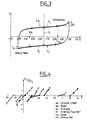
- Voltamograms such as that illustrated in FIG. 3, have an overall hysteresis-type form which allows access to a precise determination of the range of difference in interfacial potential limit ⁇ E I limit.
- a determination is obtained according to the invention by measuring the ratio between the faradaic and capacitive currents ⁇ I f / ⁇ I c , ⁇ I f being the sum of the faradaic currents and ⁇ I c , the sum of the constant capacitive currents obtained in the range of use ⁇ E I.
- the corresponding curves, known as faradic current are illustrated in FIG. 4 for the various mass materials: vitreous carbon, titanium, nickel, "uranus B6" (alloy based on Fe, with 25% of Ni, 20% of Cr, 4.5% Mo, 1.5% Cu), "316L stainless steel” and DSA "B".
- ⁇ I f and ⁇ I c corresponding to the mathematical integration of the values of the intensity of the currents on the corresponding potential ranges. They are directly measured, respectively, by the sum of the areas of the surfaces Sf a and Sf c ( Figure 3), corresponding to the presence of farada currents, I fa and I fc , for the potential values beyond the admissible range.
- ⁇ E I on the one hand and, on the other hand, at the surface Sc corresponding to the presence of the capacitive current I c in the range ⁇ E I.
- the value of the slopes of the anodic and cathodic farada current curves presented by the linear parts of the curves represented in FIG. 4 can provide a risk criterion: the lower these slopes, the more the excess of faradic harmful reaction triggered in the case of accidentally exceeding the ⁇ E I range is limited.
- titanium "T40” undergoes a passivation wave irreversible following the formation of an oxidized insulating layer when the potential exceeds 1.3 volts with respect to the electrode reference, while nickel and stainless steel "316L” undergo a strong current of dissolution when their anodic limit potential is exceeded.
- Tables Ia and Ib present the results obtained respectively for the various mass materials of electrodes and for materials of DSA type ("B";"C” in equal proportions of IrO 2 and Ta 2 O 5 , "LZA” coating in IrO 2 and RuO 2 , “Beer” coating in RuO 2 and “PITA” coating in IrO 2 and Ta 2 O 2 ).
- the range of admissible potential difference ⁇ E I is compared, for each material, with the value of the drop in interfacial potential measured directly under ohmic heating conditions. This comparison makes it possible to check whether this value is within the admissible range. Otherwise, the operating conditions should be adjusted, that is to say increasing the frequency of the applied voltage or decreasing the current density. Such an adjustment decreases the value of the drop in interfacial potential. When this value falls below the value of the admissible range, the material of the electrodes is suitable for ohmic heating, in the sense that an absence of triggering of electrochemical reaction is guaranteed.
- an increase in frequency of the voltage (60 volts rms), passing for example from 50 Hz to 2500 Hz, allows a decrease in interfacial potential drop from 0.5 V to 1 V depending on the material.
- a reduction in the current density from 5000 A / m 2 to 2500 A / m 2 at 50 Hz allows for the DSA "B" a reduction in potential drop from 0.65 V to 0.35 V.
- the method consists in measuring the potential difference between a ohmic heating electrode, consisting of the material to be tested, and a measurement probe whose distance to this electrode varies; then to vary the distance between this electrode and the probe, and to extrapolate to zero distance the regression line obtained from the different values of potential difference measured for different distances.
- the value of the intercept, halved due to the measurement peak-to-peak (not instant measurement) then represents the value of the difference in interfacial potential, characteristic of the material in the ohmic heating conditions.
- FIG. 5 illustrates two example diagrams obtained for electrodes made of DSA material "B", in a cell containing a corrosive sodium chloride solution at 20 g per liter, a voltage equal to 60 effective volts being applied across the terminals of the cell , with a current density of 5200 A / m 2 , and a temperature of 60 ° C.
- the extrapolated value ⁇ E i is 1.3 volts measured peak to peak, that is to say 0.65 volts maximum in instantaneous value, the applied voltage being respectively that of the sector, of frequency equal to 50 Hz, straight (A ), and a frequency voltage equal to 2500 Hz, right (B).
- a significant increase in frequency causes a decrease in drop in interfacial potential ⁇ E i , equal to 0.3 V (in instantaneous value) in the present case.
- the probe 10 is a platinum rod with a diameter equal to 1 mm, mounted on a support 11 capable of carrying out measurement steps of small amplitude, from a few tenths of a millimeter to less than 0.1 mm, and near the working electrode.
- the probe is 10 cm long and is coated with a heat-shrinkable sheath G on the part of the probe immersed in the cell solution.
- the rod is mounted on cell 12 using a cable gland 13, the X'X axis of the probe being at a distance equal to 13 mm from the axis of the electrode tested 14.
- a seal at silicone base is added between the probe and the cable gland.
- the part of the plunging probe 10 is curved so as to obtain contact between the refined end of the probe and the electrode to be tested 14. This end is flat and is in the form of a platinum disc of equal diameter at 0.1 mm.
- a protractor 15 is fitted on the main axis X'X of the probe and index tracking system 16 is arranged perpendicular to the X'X axis of the probe.
- the difference is measured potential between the probe and the electrode to be tested 14 connected to the ground of a oscilloscope (not shown) on a first measurement channel of the oscilloscope, as well as the total voltage ⁇ U applied between the electrode measurement and the other electrode (14 ') of the cell, on a second path of measured.
- the rotation of the probe around its axis increments the measurement by ten measurement points of the potential drop.
- the uncertainty of the measurement of the locations of the distance d results irregularity of the apparent surface of the platinum probe, this surface varying with the rotation of the vertical axis X'X of the platinum rod. To reduce this uncertainty, the diameter of the platinum probe is minimized to 0.1 mm.
- Table II brings together the values of the interfacial potential difference measured ⁇ E i for different materials constituting the electrode tested, under the conditions described above (in particular at 50 Hz of frequency and 5000 A / m 2 of density of current). Also shown in this table are the values of the ranges of admissible interfacial potential ⁇ E i of these same materials, as established by voltammetric analysis, as well as the values of the roughness.
- a global parameter integrating the drop in interfacial potential ⁇ E i and the interfacial electrical capacitance Ci of each material, is below used to serve as comparison criterion.
- This global parameter equal to ⁇ Ei.C i 2 , is characteristic of the heating energy of a material traversed by an electric current in a solution where heat is produced by the Joule effect.
- Solid materials have global parameters whose values are incommensurate with those of DSA materials, since they differ by a factor of 10 4 to 10 5 .
- the apparently most efficient solid material of solid materials namely vitreous carbon, presents significant uncertainties on the determination of interfacial capacities, greater than 50%. These uncertainties are due to the fact that the interfacial capacitance is sensitive to the surface state of the electrodes, and that this state is very variable for the material in question.
- the global parameter (C i 2 . ⁇ E i ) of DSA materials is calculated from measurements of the range of admissible interfacial potential ⁇ E i from an aqueous solution of sodium chloride at 20 g per liter, the values of the capacities Ci, determined according to the previously indicated protocol, have particularly stable values at the scanning speed of 100 mV / s.
- DSA materials are more resistant to an overvoltage at their interface, due to a smaller increase in farada current, which results in regression slopes of the farada current curves ( ⁇ I f / ⁇ I c ) lower for DSA materials, beyond the limit potential ranges ⁇ E i , as illustrated in Figure 4.
- a limited surface roughness defined as the variation maximum of the difference between the height of the asperities and the base surface is preferable, especially for food applications for reasons of hygiene and fouling.
- the influence of the temperature is not critical insofar as its variation, which uses compensatory phenomena, results in a conservation of the global parameter C i 2 . ⁇ E i ; thus an increase in temperature, which can reach values of the order of 140 ° C. in ohmic heating, has a penalizing effect on the admissible potential range ⁇ E i , largely offset by a beneficial effect on the value of the interfacial capacity.
- the invention is not limited to the applications mentioned and can by example apply to other techniques where materials under tension are in contact with a product, for example in the techniques pulsed electric fields (CEP for short).
- CEP pulsed electric fields
Landscapes
- Life Sciences & Earth Sciences (AREA)
- Engineering & Computer Science (AREA)
- Wood Science & Technology (AREA)
- Zoology (AREA)
- Chemical & Material Sciences (AREA)
- Food Science & Technology (AREA)
- Polymers & Plastics (AREA)
- Investigating Or Analyzing Materials By The Use Of Electric Means (AREA)
- Testing Resistance To Weather, Investigating Materials By Mechanical Methods (AREA)
Abstract
Description
- la figure 1, une modélisation du comportement électrique de la cellule de chauffage ohmique;
- la figure 2 illustre un montage de voltampérométrie cyclique apte à déterminer les valeurs limites, anodique et cathodique, de la chute de potentiel interfaciale d'une électrode;
- la figure 3, un voltammogramme I = f(E) obtenu pour un matériau de type DSA "B";
- la figure 4, des courbes de courant faradique pour différents matériaux massiques et à revêtement de type DSA;
- la figure 5, un diagramme de mesures de chutes de potentiel obtenues entre une électrode en matériau DSA "B" et une sonde de platine disposées à différentes distances rapprochées;
- la figure 6, un appareillage utilisé pour obtenir les mesures de chutes de potentiel interfaciales.
- une branche capacitive, B1, comportant un condensateur de capacité Ci , correspondant à la capacité interfaciale de l'électrode, formée par le va-et-vient des charges du courant alternatif (à la manière de la charge et la décharge d'un condensateur, d'où le modèle utilisé), ce va-et-vient formant le courant capacitif Ic qui génère l'effet Joule sans déclencher de réaction chimique : le courant capacitif Ic est le courant utile en chauffage ohmique ;
- une branche d'impédance à seuil, traduisant les réactions électrochimiques de l'interface suivant le sens du courant alternatif appliqué ; un modèle simple est constitué par une sous-branche dite réductrice SB2 et une sous-branche dite oxydante SB3, comportant chacune une diode de sens opposé, respectivement Dred et Dox, en série avec une résistance, respectivement rred et rox; les diodes laissent passer le courant dans le sens correspondant à celui de la demi-période de la tension alternative appliquée, dans la branche oxydante SB3 lorsque l'électrode correspondante est anode, et dans le sens réductrice SB2 lorsque l'électrode est cathode.
| Matériaux | Hastelloy | Carbone vitreux | Titane | Nickel | Uranus | Inox "316L" |
| EIa(V) | 0,175 | 0,525 | 1,2 | 0,05 | 0,4 | 0,275 |
| EIc(V) | -0,125 | 0,225 | 0 | -0,25 | 0 | -0,05 |
| ΔEI(V) | 0,3 | 0,3 | 1,2 | 0,3 | 0,4 | 0,325 |
| Matériaux DSA | "B" | "C" | LZA | "BEER" | "PITA" |
| EIa | 0,9 | 0,85 | 1,2 | 0,15 | 0,5 |
| EIc | 0,2 | -0,1 | 0,55 | 0,6 | -0,5 |
| ΔEI | 0,7 | 0,45 | 0,65 | 0,45 | 1 |
| Matériau | DSA "A" (RuO2) | DSA "B" | DSA "C" | Carbone vitreux | Inox | Hastelloy | Titane |
| ΔEi(V) | 0,7 | 0,65 | 0,65 | 2,3 | 2,5 | 2,7 | 4,8 |
| ΔEi(V) | 0,7 1 à 2 | >0,65 | 1 | 0,3 | 0,325 | 0,3 | 1,2 |
| Rugosité (µm) | 1,3 | 0,7 | 1,8 | 0,6 | 0,05 | 0,08 | 0,1 |
| Matériaux massifs | Acier Inox | Titane | Carbone vitreux | Nickel | Hastelloy |
| Ci(µF/cm2) | 35 | 50 | 260 | 27 | 63 |
| ΔEi(V) | 0,325 | 1,2 | 0,3 | 0,3 | 0,3 |
| Ci 2.ΔEi | 1 | 7,5 | 51 | 0.5 | 3 |
| Matériaux DSA | "B" | C | LZA | "BEER" | "PITA" |
| Ci(µF/cm2) | 1900 | 5600 | 27000 | 44000 | 39000 |
| ΔEi(V) | 0.7 | 0,45 | 0,65 | 0,45 | 1 |
| Ci 2.ΔEi | 0,06.106 | 0,35.106 | 1,2.106 | 2,2.106 | 3,8.106 |
| Rugosité (µm) | 0,7 | 1,8 | 6,96 | 3,22 | - |
Claims (15)
- Procédé de détermination du comportement électrochimique d'un matériau d'électrode, caractérisé en ce qu'il consiste à mesurer par voltampérométrie dans une solution saline, l'intensité (I) du courant électrique circulant entre l'électrode testée (1) et une contre-électrode en fonction d'une différence de potentiel (ΔU) entre l'électrode testée et une électrode de référence, cette différence de potentiel variant selon un balayage périodique sur une plage de valeurs suffisante pour engendrer, aux extrémités de cette plage, des courants (Ifa, Ifc) à variation non linéaire en fonction du potentiel appliqué, et à déterminer une plage de valeurs de potentiel admissible (ΔEi) pour un chauffage ohmique, dans laquelle le courant varie linéairement en fonction du potentiel et au-delà de laquelle le seuil énergétique de déclenchement de réactions électrochimiques est franchi.
- Dispositif de mise en oeuvre du procédé selon la revendication 1, comportant des moyens de mesure de type voltampérométrie cyclique à trois électrodes disposées dans une cellule (4), un potentiostat (5) appliqué aux bornes (2, 3) de la cellule (4) pour imposer à l'électrode de travail (1) une valeur de potentiel variable, un générateur de signal (6) qui, couplé à la cellule (4) via le potentiostat (5), applique aux bornes de la cellule un signal périodique,
caractérisé en ce que la cellule contient une solution saline corrosive, en ce que le signal appliquée est une tension de type triangulaire dont les valeurs de potentiels d'inversion sont ajustées de sorte que les courants capacitifs générés (Ifc, Ifa) soient sensiblement équivalents, et en ce que le circuit est complété par des moyens de visualisation (7), constitués par un oscilloscope et une table traçante, reliés au potentiostat (5) et à la cellule (4) entre les bornes d'un shunt (8). - Procédé selon la revendication 1, caractérisé en ce que la détermination de la plage de chutes de potentiel admissible (ΔEi) est obtenue en reportant, sur une courbe de courant faradique, le rapport entre les courants faradiques et capacitif (ΣIf/ΣIc) sur la totalité du domaine balayé, égal au rapport des aires de surface correspondantes mesurées sur la courbe de voltampérométrie par intégration des valeurs d'intensité des courants sur les plages de chute de potentiel interfaciales correspondantes.
- Procédé selon la revendication 3, caractérisé en qu'un critère de risque au-delà de la plage de chutes de potentiel limites (ΔEi) est défini par la pente linéaire de la courbe de courant faradique (ΣIf/ΣIc) dans les plages de valeurs de chutes de potentiel allant au-delà des valeurs limites.
- Procédé de mesure de chute de potentiel interfaciale électrode-solution dans les conditions de chauffage ohmique, caractérisé en ce qu'il consiste à utiliser une sonde disposée à différentes distances de l'électrode à tester, à déduire les mesures de distance de mesures angulaires de la rotation de l'électrode de référence, et à déterminer la chute de potentiel interfaciale (ΔEi) par extrapolation linéaire à distance nulle des différentes valeurs de potentiel mesurées entre l'électrode testée et la sonde.
- Dispositif de mise en oeuvre du procédé selon la revendication 5, caractérisé en ce qu'il comporte, comme sonde de mesure, une sonde à fil de platine d'axe vertical (X'X) et de diamètre sensiblement égal ou inférieur à 0,1 mm, ce fil étant recourbé à son extrémité pour venir en contact avec l'électrode testée et un index de mesure de déviation angulaire de l'axe (X'X) du fil disposé sur cet axe.
- Dispositif selon la revendication 6, caractérisé en ce que la sonde de mesure est revêtue d'une gaine thermorétractable sur sa partie immergée dans la solution, en ce que la sonde est montée sur la cellule (12) à l'aide d'un presse-étoupe (13), en ce qu'un joint à base de silicone est ajouté entre la sonde et le presse-étoupe pour assurer la rotation de la sonde à l'intérieur du presse-étoupe, et en ce que la tension interfaciale est mesurée entre l'électrode à tester (14) et la sonde sur une première voie de l'oscilloscope, alors que la tension totale appliquée (AU) est mesurée entre les électrodes (14, 14') de la cellule sur une deuxième voie de mesure de l'oscilloscope.
- Application à l'adaptation des conditions de chauffage ohmique au matériau d'électrode utilisé, caractérisé en ce que, pour chaque matériau, la valeur de chute de potentiel interfaciale (ΔEi) mesurée selon la revendication 5 est comparée à la plage de valeurs de potentiel admissible (ΔEi) déterminée selon la revendication 1, et ce que la fréquence de la tension et la densité de courant appliquées sont adaptées pour que la chute de potentiel interfacial reste inférieure à la plage de potentiel admise (ΔEi).
- Application à la sélection de matériaux constitutifs d'électrodes aptes au chauffage ohmique, caractérisé en ce qu'un critère global de classement, représentatif de l'énergie de chauffe obtenue, et égal au produit de la plage de potentiel interfaciale admissible (ΔEi), déterminée selon le procédé de la revendication 3, par le carré de la capacité interfaciale (Ci) de l'électrode dont le matériau constitutif est testé.
- Application selon la revendication 9 à la sélection de matériaux aptes aux techniques à champs pulsés.
- Matériaux aptes au chauffage ohmique et sélectionnés à l'aide du paramètre global conformément à la revendication 9, caractérisés en ce que ces matériaux sont de type DSA, constitués d'un support en titane recouvert de couches de semi-conducteur formées d'un oxyde de métal noble, ces matériaux formant le revêtement d'électrodes de chauffage ohmique à base de titane.
- Appareil de chauffage ohmique comportant des électrodes en matériau de type DSA comportant un substrat en titane recouvert d'au moins une couche d'oxydes métalliques de métaux nobles choisis parmi le Ruthénium, le Tantale, l'Iridium et leurs mélanges.
- Appareil selon la revendication 12, caractérisé en ce que la couche d'oxyde comporte au moins deux desdits oxydes métalliques dans des proportions allant de 25/75 à 75/25 en poids.
- Procédé de chauffage ohmique dans lequel on utilise des électrodes en matériau de type DSA.
- Utilisation pour la fabrication d'électrodes pour le chauffage ohmique de matériau de type DSA.
Applications Claiming Priority (2)
| Application Number | Priority Date | Filing Date | Title |
|---|---|---|---|
| FR9803154A FR2776073B1 (fr) | 1998-03-13 | 1998-03-13 | Procede de determination du comportement electrochimique d'un materiau d'electrode et de mesure de chute de potentiel interfaciale electrode/solution dans les conditions de chauffage ohmique, dispositif et applications a cet effet |
| FR9803154 | 1998-03-13 |
Publications (3)
| Publication Number | Publication Date |
|---|---|
| EP0942629A1 true EP0942629A1 (fr) | 1999-09-15 |
| EP0942629B1 EP0942629B1 (fr) | 2008-11-19 |
| EP0942629B8 EP0942629B8 (fr) | 2009-03-18 |
Family
ID=9524053
Family Applications (1)
| Application Number | Title | Priority Date | Filing Date |
|---|---|---|---|
| EP99400623A Expired - Lifetime EP0942629B8 (fr) | 1998-03-13 | 1999-03-12 | Procédé de détermination du comportement électrochimique d'un matériau d'électrode et de mesure de chute de potentiel interfaciale et dispositif de chauffage ohmique |
Country Status (4)
| Country | Link |
|---|---|
| EP (1) | EP0942629B8 (fr) |
| DE (1) | DE69939917D1 (fr) |
| ES (1) | ES2317687T3 (fr) |
| FR (1) | FR2776073B1 (fr) |
Cited By (1)
| Publication number | Priority date | Publication date | Assignee | Title |
|---|---|---|---|---|
| IT201900006559A1 (it) | 2019-05-06 | 2020-11-06 | Emmepiemme S R L | Riscaldatore ohmico a campo radiale e elettrodo flottante e relativo metodo di utilizzo. |
Citations (3)
| Publication number | Priority date | Publication date | Assignee | Title |
|---|---|---|---|---|
| EP0418404A1 (fr) * | 1989-09-15 | 1991-03-27 | Hewlett-Packard GmbH | Méthode de détermination des conditions de travail optimales dans un détecteur électrochimique et détecteur électrochimique utilisant cette méthode |
| US5235905A (en) * | 1985-05-31 | 1993-08-17 | Foodco Corporation | High pulsed voltage systems for extending the shelf life of pumpable food products |
| US5609900A (en) * | 1993-09-23 | 1997-03-11 | Reznik; David | Electroheating of food products using low frequency current |
-
1998
- 1998-03-13 FR FR9803154A patent/FR2776073B1/fr not_active Expired - Fee Related
-
1999
- 1999-03-12 EP EP99400623A patent/EP0942629B8/fr not_active Expired - Lifetime
- 1999-03-12 DE DE69939917T patent/DE69939917D1/de not_active Expired - Lifetime
- 1999-03-12 ES ES99400623T patent/ES2317687T3/es not_active Expired - Lifetime
Patent Citations (3)
| Publication number | Priority date | Publication date | Assignee | Title |
|---|---|---|---|---|
| US5235905A (en) * | 1985-05-31 | 1993-08-17 | Foodco Corporation | High pulsed voltage systems for extending the shelf life of pumpable food products |
| EP0418404A1 (fr) * | 1989-09-15 | 1991-03-27 | Hewlett-Packard GmbH | Méthode de détermination des conditions de travail optimales dans un détecteur électrochimique et détecteur électrochimique utilisant cette méthode |
| US5609900A (en) * | 1993-09-23 | 1997-03-11 | Reznik; David | Electroheating of food products using low frequency current |
Non-Patent Citations (2)
| Title |
|---|
| DATABASE INSPEC INSTITUTE OF ELECTRICAL ENGINEERS, STEVENAGE, GB; May 1993 (1993-05-01), P. LE PEURIAN, Y. QUEFFÉLEC: "UNE NOUVELLE APPLICATION DE L'EFFET JOULE POUR RÉCHAUFFER LES FLUIDES INDUSTRIELS: LE CHAFFAGE OHMIQUE", XP002085902 * |
| R. ZITNY, J. SESTAK: "DIRECT OHMIC HEATING IN LAMINAR FLOWS IN DUCTS", ACTA POLYTECHNICA, vol. 36, no. 4, 1996, TECH. UNIV. PRAGUE, CZECH REPUBLIC, pages 71 - 83, XP002085901 * |
Cited By (1)
| Publication number | Priority date | Publication date | Assignee | Title |
|---|---|---|---|---|
| IT201900006559A1 (it) | 2019-05-06 | 2020-11-06 | Emmepiemme S R L | Riscaldatore ohmico a campo radiale e elettrodo flottante e relativo metodo di utilizzo. |
Also Published As
| Publication number | Publication date |
|---|---|
| EP0942629B8 (fr) | 2009-03-18 |
| DE69939917D1 (de) | 2009-01-02 |
| EP0942629B1 (fr) | 2008-11-19 |
| ES2317687T3 (es) | 2009-04-16 |
| FR2776073A1 (fr) | 1999-09-17 |
| FR2776073B1 (fr) | 2000-08-04 |
Similar Documents
| Publication | Publication Date | Title |
|---|---|---|
| Zeng et al. | Stripping voltammetric analysis of heavy metals at nitrogen doped diamond‐like carbon film electrodes | |
| Worsley et al. | Mechanistic changes in cut-edge corrosion induced by variation of organic coating porosity | |
| Kiran et al. | Boron doped diamond electrodes for direct measurement in biological fluids: an in situ regeneration approach | |
| WO2010082006A1 (fr) | Micro-capteur réalisé en technologies microsystèmes pour la mesure et/ou la détection de l'encrassement | |
| Daniele et al. | Recent developments in stripping analysis on microelectrodes | |
| CH706122B1 (fr) | Procédé de détection de changements de la qualité de l'eau. | |
| Martínez-Ibernón et al. | Characterization of electrochemical systems using potential step voltammetry. Part II: Modeling of reversible systems | |
| EP0942629B1 (fr) | Procédé de détermination du comportement électrochimique d'un matériau d'électrode et de mesure de chute de potentiel interfaciale et dispositif de chauffage ohmique | |
| US3951161A (en) | Method of detecting the onset of formation of adherent precipitates on surfaces immersed in liquids, and controlling the formation of such precipitates | |
| FR2695203A1 (fr) | Détecteur de liquide à thermistance. | |
| Andion et al. | Corrosion behaviour at the interface of steel bars embedded in cement slurries: Effect of phenol polymer coatings | |
| EP1592959B1 (fr) | Methode de test de reservoir cryogenique comportant une protection cathodique | |
| Brown et al. | Free‐Standing Phytantriol Q224 Cubic‐Phase Films: Resistivity Monitoring and Switching | |
| Betova et al. | Conduction mechanism in oxide films on ferrous alloys studied by impedance spectroscopy in symmetrical and asymmetrical configurations | |
| WO1983001514A1 (fr) | Procede pour detecter les defauts d'un revetement dielectrique a la surface d'un substrat electriquement conducteur | |
| Vieira et al. | The use of cyclic voltammetry to detect biofilms formed by Pseudomonas fluorescens on platinum electrodes | |
| Dumitrascu et al. | Improving the corrosion behaviour of 6061 aluminum alloy by controlled anodic formed oxide layer | |
| Gusmano et al. | On-line corrosion resistance tests in sea water on metals for MED plants | |
| EP2212674A1 (fr) | Procede et dispositif de mesure de l'evolution d'un depot sur une surface en contact avec un fluide aqueux | |
| WO2003048426A2 (fr) | Procede et dispositif de detection des effets d'anode d'une cellule d'electrolyse pour la production d'aluminium | |
| Minciuna et al. | Electrochemical behaviour of CoCrMo and CoCrMoSi5 alloys at different simulated physiological medium | |
| Fulian et al. | Laser activated voltammetry: application to the determination of phenol in aqueous solution at a glassy carbon electrode | |
| Timmermans et al. | Electrodeposition of insulating poly (phenylene oxide) films with variable thickness | |
| Prado et al. | Electrodeposition of Lead at Boron‐Doped Diamond Film Electrodes: Effect of Temperature | |
| EP1091209A1 (fr) | Capteur électrochimique à autodiagnostic |
Legal Events
| Date | Code | Title | Description |
|---|---|---|---|
| PUAI | Public reference made under article 153(3) epc to a published international application that has entered the european phase |
Free format text: ORIGINAL CODE: 0009012 |
|
| AK | Designated contracting states |
Kind code of ref document: A1 Designated state(s): DE ES FR GB GR IE IT NL SE |
|
| AX | Request for extension of the european patent |
Free format text: AL;LT;LV;MK;RO;SI |
|
| RIN1 | Information on inventor provided before grant (corrected) |
Inventor name: HEBERT, SEBASTIEN Inventor name: LAURENT, MARIE-HELENE Inventor name: BERTHOU, MARC |
|
| 17P | Request for examination filed |
Effective date: 20000306 |
|
| AKX | Designation fees paid |
Free format text: DE ES FR GB GR IE IT NL SE |
|
| RAP1 | Party data changed (applicant data changed or rights of an application transferred) |
Owner name: ELECTRICITE DE FRANCE, SOCIETE ANONYME |
|
| 17Q | First examination report despatched |
Effective date: 20051129 |
|
| RIC1 | Information provided on ipc code assigned before grant |
Ipc: H05B 3/12 20060101ALI20071213BHEP Ipc: H05B 3/03 20060101AFI20071213BHEP |
|
| RTI1 | Title (correction) |
Free format text: PROCESS FOR DETERMINING THE ELECTROCHEMICAL BEHAVIOUR OF AN ELECTRODE MATERIAL AND FOR MEASURING THE INTERFACIAL POTENTIAL DROP AND APPARATUS FOR OHMIC HEATING |
|
| GRAP | Despatch of communication of intention to grant a patent |
Free format text: ORIGINAL CODE: EPIDOSNIGR1 |
|
| GRAS | Grant fee paid |
Free format text: ORIGINAL CODE: EPIDOSNIGR3 |
|
| GRAF | Information related to payment of grant fee modified |
Free format text: ORIGINAL CODE: EPIDOSCIGR3 |
|
| GRAL | Information related to payment of fee for publishing/printing deleted |
Free format text: ORIGINAL CODE: EPIDOSDIGR3 |
|
| GRAS | Grant fee paid |
Free format text: ORIGINAL CODE: EPIDOSNIGR3 |
|
| GRAA | (expected) grant |
Free format text: ORIGINAL CODE: 0009210 |
|
| AK | Designated contracting states |
Kind code of ref document: B1 Designated state(s): DE ES FR GB GR IE IT NL SE |
|
| REG | Reference to a national code |
Ref country code: GB Ref legal event code: FG4D Free format text: NOT ENGLISH |
|
| REG | Reference to a national code |
Ref country code: IE Ref legal event code: FG4D Free format text: LANGUAGE OF EP DOCUMENT: FRENCH |
|
| REF | Corresponds to: |
Ref document number: 69939917 Country of ref document: DE Date of ref document: 20090102 Kind code of ref document: P |
|
| RAP2 | Party data changed (patent owner data changed or rights of a patent transferred) |
Owner name: ELECTRICITE DE FRANCE |
|
| REG | Reference to a national code |
Ref country code: GR Ref legal event code: EP Ref document number: 20090400106 Country of ref document: GR |
|
| NLT2 | Nl: modifications (of names), taken from the european patent patent bulletin |
Owner name: ELECTRICITE DE FRANCE Effective date: 20090114 |
|
| REG | Reference to a national code |
Ref country code: SE Ref legal event code: TRGR |
|
| REG | Reference to a national code |
Ref country code: ES Ref legal event code: FG2A Ref document number: 2317687 Country of ref document: ES Kind code of ref document: T3 |
|
| NLXE | Nl: other communications concerning ep-patents (part 3 heading xe) |
Free format text: PAT. BUL. 04/2009, PAGE 519: CORR.: ELECTRICITE DE FRANCE. |
|
| PLBE | No opposition filed within time limit |
Free format text: ORIGINAL CODE: 0009261 |
|
| STAA | Information on the status of an ep patent application or granted ep patent |
Free format text: STATUS: NO OPPOSITION FILED WITHIN TIME LIMIT |
|
| 26N | No opposition filed |
Effective date: 20090820 |
|
| PGFP | Annual fee paid to national office [announced via postgrant information from national office to epo] |
Ref country code: IE Payment date: 20140228 Year of fee payment: 16 Ref country code: DE Payment date: 20140311 Year of fee payment: 16 Ref country code: NL Payment date: 20140224 Year of fee payment: 16 Ref country code: SE Payment date: 20140313 Year of fee payment: 16 |
|
| PGFP | Annual fee paid to national office [announced via postgrant information from national office to epo] |
Ref country code: GR Payment date: 20140218 Year of fee payment: 16 Ref country code: ES Payment date: 20140320 Year of fee payment: 16 Ref country code: IT Payment date: 20140314 Year of fee payment: 16 |
|
| PGFP | Annual fee paid to national office [announced via postgrant information from national office to epo] |
Ref country code: GB Payment date: 20140317 Year of fee payment: 16 |
|
| PGFP | Annual fee paid to national office [announced via postgrant information from national office to epo] |
Ref country code: FR Payment date: 20140331 Year of fee payment: 16 |
|
| REG | Reference to a national code |
Ref country code: DE Ref legal event code: R119 Ref document number: 69939917 Country of ref document: DE |
|
| GBPC | Gb: european patent ceased through non-payment of renewal fee |
Effective date: 20150312 |
|
| PG25 | Lapsed in a contracting state [announced via postgrant information from national office to epo] |
Ref country code: SE Free format text: LAPSE BECAUSE OF NON-PAYMENT OF DUE FEES Effective date: 20150313 |
|
| REG | Reference to a national code |
Ref country code: SE Ref legal event code: EUG |
|
| REG | Reference to a national code |
Ref country code: NL Ref legal event code: MM Effective date: 20150401 |
|
| REG | Reference to a national code |
Ref country code: GR Ref legal event code: ML Ref document number: 20090400106 Country of ref document: GR Effective date: 20151002 |
|
| PG25 | Lapsed in a contracting state [announced via postgrant information from national office to epo] |
Ref country code: IT Free format text: LAPSE BECAUSE OF NON-PAYMENT OF DUE FEES Effective date: 20150312 |
|
| REG | Reference to a national code |
Ref country code: FR Ref legal event code: ST Effective date: 20151130 |
|
| REG | Reference to a national code |
Ref country code: IE Ref legal event code: MM4A |
|
| PG25 | Lapsed in a contracting state [announced via postgrant information from national office to epo] |
Ref country code: DE Free format text: LAPSE BECAUSE OF NON-PAYMENT OF DUE FEES Effective date: 20151001 Ref country code: GR Free format text: LAPSE BECAUSE OF NON-PAYMENT OF DUE FEES Effective date: 20151002 Ref country code: GB Free format text: LAPSE BECAUSE OF NON-PAYMENT OF DUE FEES Effective date: 20150312 Ref country code: IE Free format text: LAPSE BECAUSE OF NON-PAYMENT OF DUE FEES Effective date: 20150312 |
|
| PG25 | Lapsed in a contracting state [announced via postgrant information from national office to epo] |
Ref country code: FR Free format text: LAPSE BECAUSE OF NON-PAYMENT OF DUE FEES Effective date: 20150331 |
|
| REG | Reference to a national code |
Ref country code: ES Ref legal event code: FD2A Effective date: 20170428 |
|
| PG25 | Lapsed in a contracting state [announced via postgrant information from national office to epo] |
Ref country code: NL Free format text: LAPSE BECAUSE OF NON-PAYMENT OF DUE FEES Effective date: 20150401 Ref country code: ES Free format text: LAPSE BECAUSE OF NON-PAYMENT OF DUE FEES Effective date: 20150313 |
|
| PG25 | Lapsed in a contracting state [announced via postgrant information from national office to epo] |
Ref country code: ES Free format text: LAPSE BECAUSE OF NON-PAYMENT OF DUE FEES Effective date: 20160313 |