EP0942629B1 - Verfahren zum Erfassen des elektrochemisches Verhalten eines Elektrodenmaterial und zum Messen des Spannunsabfalls an den Phasengrenzflächen und Verfahren zum ohmischen Heizen - Google Patents
Verfahren zum Erfassen des elektrochemisches Verhalten eines Elektrodenmaterial und zum Messen des Spannunsabfalls an den Phasengrenzflächen und Verfahren zum ohmischen Heizen Download PDFInfo
- Publication number
- EP0942629B1 EP0942629B1 EP99400623A EP99400623A EP0942629B1 EP 0942629 B1 EP0942629 B1 EP 0942629B1 EP 99400623 A EP99400623 A EP 99400623A EP 99400623 A EP99400623 A EP 99400623A EP 0942629 B1 EP0942629 B1 EP 0942629B1
- Authority
- EP
- European Patent Office
- Prior art keywords
- electrode
- probe
- potential
- electrodes
- current
- Prior art date
- Legal status (The legal status is an assumption and is not a legal conclusion. Google has not performed a legal analysis and makes no representation as to the accuracy of the status listed.)
- Expired - Lifetime
Links
- 238000010438 heat treatment Methods 0.000 title claims description 53
- 238000000034 method Methods 0.000 title claims description 17
- 239000007772 electrode material Substances 0.000 title description 2
- 230000008569 process Effects 0.000 title description 2
- 239000000463 material Substances 0.000 claims description 74
- 239000000523 sample Substances 0.000 claims description 34
- 238000005259 measurement Methods 0.000 claims description 27
- 238000003487 electrochemical reaction Methods 0.000 claims description 19
- BASFCYQUMIYNBI-UHFFFAOYSA-N platinum Chemical compound [Pt] BASFCYQUMIYNBI-UHFFFAOYSA-N 0.000 claims description 16
- RTAQQCXQSZGOHL-UHFFFAOYSA-N Titanium Chemical compound [Ti] RTAQQCXQSZGOHL-UHFFFAOYSA-N 0.000 claims description 9
- 229910052719 titanium Inorganic materials 0.000 claims description 9
- 239000010936 titanium Substances 0.000 claims description 9
- 229910052697 platinum Inorganic materials 0.000 claims description 8
- 229910052707 ruthenium Inorganic materials 0.000 claims description 4
- KJTLSVCANCCWHF-UHFFFAOYSA-N Ruthenium Chemical compound [Ru] KJTLSVCANCCWHF-UHFFFAOYSA-N 0.000 claims description 3
- 229910052741 iridium Inorganic materials 0.000 claims description 3
- 229910000510 noble metal Inorganic materials 0.000 claims description 3
- 229910052715 tantalum Inorganic materials 0.000 claims description 3
- 238000013213 extrapolation Methods 0.000 claims description 2
- GKOZUEZYRPOHIO-UHFFFAOYSA-N iridium atom Chemical compound [Ir] GKOZUEZYRPOHIO-UHFFFAOYSA-N 0.000 claims description 2
- 229920001296 polysiloxane Polymers 0.000 claims description 2
- 239000000758 substrate Substances 0.000 claims description 2
- GUVRBAGPIYLISA-UHFFFAOYSA-N tantalum atom Chemical compound [Ta] GUVRBAGPIYLISA-UHFFFAOYSA-N 0.000 claims description 2
- 238000012856 packing Methods 0.000 claims 3
- 229910044991 metal oxide Inorganic materials 0.000 claims 2
- 239000000203 mixture Substances 0.000 claims 1
- 238000002408 directed self-assembly Methods 0.000 description 31
- 239000000243 solution Substances 0.000 description 16
- PXHVJJICTQNCMI-UHFFFAOYSA-N Nickel Chemical compound [Ni] PXHVJJICTQNCMI-UHFFFAOYSA-N 0.000 description 8
- FAPWRFPIFSIZLT-UHFFFAOYSA-M Sodium chloride Chemical compound [Na+].[Cl-] FAPWRFPIFSIZLT-UHFFFAOYSA-M 0.000 description 8
- 238000000576 coating method Methods 0.000 description 6
- 229910001220 stainless steel Inorganic materials 0.000 description 6
- 239000010935 stainless steel Substances 0.000 description 6
- 239000011248 coating agent Substances 0.000 description 5
- 230000000694 effects Effects 0.000 description 5
- 238000005868 electrolysis reaction Methods 0.000 description 5
- 235000013305 food Nutrition 0.000 description 5
- 229910021397 glassy carbon Inorganic materials 0.000 description 5
- 230000009931 harmful effect Effects 0.000 description 5
- 238000006243 chemical reaction Methods 0.000 description 4
- 239000000470 constituent Substances 0.000 description 4
- 230000007423 decrease Effects 0.000 description 4
- HTXDPTMKBJXEOW-UHFFFAOYSA-N dioxoiridium Chemical compound O=[Ir]=O HTXDPTMKBJXEOW-UHFFFAOYSA-N 0.000 description 4
- 229910000457 iridium oxide Inorganic materials 0.000 description 4
- 229910052759 nickel Inorganic materials 0.000 description 4
- 238000007254 oxidation reaction Methods 0.000 description 4
- 230000001590 oxidative effect Effects 0.000 description 4
- 230000000737 periodic effect Effects 0.000 description 4
- 238000006722 reduction reaction Methods 0.000 description 4
- OKTJSMMVPCPJKN-UHFFFAOYSA-N Carbon Chemical compound [C] OKTJSMMVPCPJKN-UHFFFAOYSA-N 0.000 description 3
- 235000013405 beer Nutrition 0.000 description 3
- 125000004122 cyclic group Chemical group 0.000 description 3
- 229910000856 hastalloy Inorganic materials 0.000 description 3
- 230000003647 oxidation Effects 0.000 description 3
- BPUBBGLMJRNUCC-UHFFFAOYSA-N oxygen(2-);tantalum(5+) Chemical compound [O-2].[O-2].[O-2].[O-2].[O-2].[Ta+5].[Ta+5] BPUBBGLMJRNUCC-UHFFFAOYSA-N 0.000 description 3
- 230000009467 reduction Effects 0.000 description 3
- 229910001925 ruthenium oxide Inorganic materials 0.000 description 3
- WOCIAKWEIIZHES-UHFFFAOYSA-N ruthenium(iv) oxide Chemical compound O=[Ru]=O WOCIAKWEIIZHES-UHFFFAOYSA-N 0.000 description 3
- 239000011780 sodium chloride Substances 0.000 description 3
- 239000011343 solid material Substances 0.000 description 3
- 229910001936 tantalum oxide Inorganic materials 0.000 description 3
- 238000011282 treatment Methods 0.000 description 3
- 238000004832 voltammetry Methods 0.000 description 3
- 238000001075 voltammogram Methods 0.000 description 3
- UQSXHKLRYXJYBZ-UHFFFAOYSA-N Iron oxide Chemical compound [Fe]=O UQSXHKLRYXJYBZ-UHFFFAOYSA-N 0.000 description 2
- 229910045601 alloy Inorganic materials 0.000 description 2
- 239000000956 alloy Substances 0.000 description 2
- 238000004458 analytical method Methods 0.000 description 2
- 239000007864 aqueous solution Substances 0.000 description 2
- 230000008901 benefit Effects 0.000 description 2
- 239000003990 capacitor Substances 0.000 description 2
- 230000015556 catabolic process Effects 0.000 description 2
- 230000008859 change Effects 0.000 description 2
- 238000006731 degradation reaction Methods 0.000 description 2
- 238000010586 diagram Methods 0.000 description 2
- 239000012530 fluid Substances 0.000 description 2
- XEEYBQQBJWHFJM-UHFFFAOYSA-N iron Substances [Fe] XEEYBQQBJWHFJM-UHFFFAOYSA-N 0.000 description 2
- 150000004706 metal oxides Chemical class 0.000 description 2
- 238000002161 passivation Methods 0.000 description 2
- XOFYZVNMUHMLCC-ZPOLXVRWSA-N prednisone Chemical compound O=C1C=C[C@]2(C)[C@H]3C(=O)C[C@](C)([C@@](CC4)(O)C(=O)CO)[C@@H]4[C@@H]3CCC2=C1 XOFYZVNMUHMLCC-ZPOLXVRWSA-N 0.000 description 2
- 241000894007 species Species 0.000 description 2
- 230000001960 triggered effect Effects 0.000 description 2
- ZAMOUSCENKQFHK-UHFFFAOYSA-N Chlorine atom Chemical compound [Cl] ZAMOUSCENKQFHK-UHFFFAOYSA-N 0.000 description 1
- 241001644893 Entandrophragma utile Species 0.000 description 1
- 241000287107 Passer Species 0.000 description 1
- 229920002472 Starch Polymers 0.000 description 1
- 229910000831 Steel Inorganic materials 0.000 description 1
- WAIPAZQMEIHHTJ-UHFFFAOYSA-N [Cr].[Co] Chemical compound [Cr].[Co] WAIPAZQMEIHHTJ-UHFFFAOYSA-N 0.000 description 1
- QUDGEUNELQKIGL-UHFFFAOYSA-N [Ti].[Ni].[C] Chemical compound [Ti].[Ni].[C] QUDGEUNELQKIGL-UHFFFAOYSA-N 0.000 description 1
- 230000006978 adaptation Effects 0.000 description 1
- QVGXLLKOCUKJST-UHFFFAOYSA-N atomic oxygen Chemical compound [O] QVGXLLKOCUKJST-UHFFFAOYSA-N 0.000 description 1
- 230000004888 barrier function Effects 0.000 description 1
- 230000009286 beneficial effect Effects 0.000 description 1
- 230000015572 biosynthetic process Effects 0.000 description 1
- 238000004364 calculation method Methods 0.000 description 1
- 229910052799 carbon Inorganic materials 0.000 description 1
- 238000003486 chemical etching Methods 0.000 description 1
- 239000003153 chemical reaction reagent Substances 0.000 description 1
- 239000000460 chlorine Substances 0.000 description 1
- 229910052801 chlorine Inorganic materials 0.000 description 1
- 229910052804 chromium Inorganic materials 0.000 description 1
- 238000010411 cooking Methods 0.000 description 1
- 230000007797 corrosion Effects 0.000 description 1
- 238000005260 corrosion Methods 0.000 description 1
- 238000002484 cyclic voltammetry Methods 0.000 description 1
- 230000003247 decreasing effect Effects 0.000 description 1
- 230000007547 defect Effects 0.000 description 1
- 230000006866 deterioration Effects 0.000 description 1
- 230000001627 detrimental effect Effects 0.000 description 1
- ZOMNIUBKTOKEHS-UHFFFAOYSA-L dimercury dichloride Chemical class Cl[Hg][Hg]Cl ZOMNIUBKTOKEHS-UHFFFAOYSA-L 0.000 description 1
- 238000006073 displacement reaction Methods 0.000 description 1
- 238000004090 dissolution Methods 0.000 description 1
- 230000005684 electric field Effects 0.000 description 1
- 230000005611 electricity Effects 0.000 description 1
- 238000005516 engineering process Methods 0.000 description 1
- 239000012847 fine chemical Substances 0.000 description 1
- 239000013505 freshwater Substances 0.000 description 1
- 238000004817 gas chromatography Methods 0.000 description 1
- 210000004907 gland Anatomy 0.000 description 1
- 230000020169 heat generation Effects 0.000 description 1
- 230000010354 integration Effects 0.000 description 1
- 230000003993 interaction Effects 0.000 description 1
- 229910052742 iron Inorganic materials 0.000 description 1
- 230000002427 irreversible effect Effects 0.000 description 1
- 238000004519 manufacturing process Methods 0.000 description 1
- 230000007246 mechanism Effects 0.000 description 1
- VMWYVTOHEQQZHQ-UHFFFAOYSA-N methylidynenickel Chemical compound [Ni]#[C] VMWYVTOHEQQZHQ-UHFFFAOYSA-N 0.000 description 1
- 229910052750 molybdenum Inorganic materials 0.000 description 1
- 239000001301 oxygen Substances 0.000 description 1
- 229910052760 oxygen Inorganic materials 0.000 description 1
- 150000003057 platinum Chemical class 0.000 description 1
- 230000010287 polarization Effects 0.000 description 1
- 239000012088 reference solution Substances 0.000 description 1
- 239000013535 sea water Substances 0.000 description 1
- 238000007789 sealing Methods 0.000 description 1
- 239000004065 semiconductor Substances 0.000 description 1
- 238000000926 separation method Methods 0.000 description 1
- 239000010802 sludge Substances 0.000 description 1
- 239000007787 solid Substances 0.000 description 1
- 239000008107 starch Substances 0.000 description 1
- 239000010959 steel Substances 0.000 description 1
- 230000001954 sterilising effect Effects 0.000 description 1
- 239000000126 substance Substances 0.000 description 1
- 230000003746 surface roughness Effects 0.000 description 1
- 230000009466 transformation Effects 0.000 description 1
- 229910052721 tungsten Inorganic materials 0.000 description 1
Images

Classifications
-
- H—ELECTRICITY
- H05—ELECTRIC TECHNIQUES NOT OTHERWISE PROVIDED FOR
- H05B—ELECTRIC HEATING; ELECTRIC LIGHT SOURCES NOT OTHERWISE PROVIDED FOR; CIRCUIT ARRANGEMENTS FOR ELECTRIC LIGHT SOURCES, IN GENERAL
- H05B3/00—Ohmic-resistance heating
- H05B3/02—Details
- H05B3/03—Electrodes
-
- A—HUMAN NECESSITIES
- A23—FOODS OR FOODSTUFFS; TREATMENT THEREOF, NOT COVERED BY OTHER CLASSES
- A23B—PRESERVATION OF FOODS, FOODSTUFFS OR NON-ALCOHOLIC BEVERAGES; CHEMICAL RIPENING OF FRUIT OR VEGETABLES
- A23B2/00—Preservation of foods or foodstuffs, in general
- A23B2/05—Preservation of foods or foodstuffs, in general by heating using irradiation or electric treatment
Definitions
- the invention relates to the field of ohmic heating, applied essentially to the agri-food, fine chemicals or effluent treatment sectors.
- ohmic heating also called direct conduction heating, allows to bake, pasteurize, sterilize particular products, heat-sensitive or viscous.
- this heating makes it possible to carry out treatments with high density of power or requiring homogeneous temperatures in all points.
- Effluent treatment consists essentially of heating and concentrating thick sludge.
- the ohmic heating is conventionally carried out in a tank having at least two electrodes. An electrical potential difference is applied across these electrodes to establish therebetween, an electric current of density equal to a few thousands of A / m 2, for example from 100 to 5000 A / m 2 with a current at 50 Hz (and more if the frequency is increased, for example 15000 A / m 2 ), depending on the product to be heated and the results to be obtained (duration, temperature). This current is thus brought into contact with the product disposed in the cell.
- the current then flows through the product which heats by the Joule effect, until reaching temperatures, depending on the case, of a few tens at 90 ° C, or even 140 ° C, for periods ranging from a few tenths of a second to several hours.
- the ohmic heating cell is supplied with alternating current to promote the Joule effect by reciprocating the ionic species contained in the solution, while, on the contrary, the direct current produces in an electrolysis cell tends to promote electrochemical reactions by electron exchange between the electrodes and the solution.
- the problem of ohmic heating is to avoid pollution or deterioration of the heated product. These degradations are due to corrosion electrodes by the passage of the current and the electrochemical reactions due to this same current. Such electrochemical reactions, even limited, may be difficult or completely unacceptable for some of the applications referred to above, such as those in the food industry, which prohibit any pollution or unwanted transformation of said product.
- the present invention proposes to analyze the variations of the electrode-solution interaction potential in order to define the conditions of occurrence of faradic currents caused by the implementation of electrochemical reactions, and to act on the parameters involved in this definition. to avoid the phenomena of pollution and electrolysis mentioned above.
- the subject of the invention is a method for determining the electrochemical behavior of a working electrode, as a function of its constituent material. This process is based on measurement voltammetric, in saline solution, of the intensity of the electric current flowing between the tested electrode and a counterelectrode as a function of a potential difference applied between the working electrode and a reference electrode, this potential difference varying according to a periodic scan over a range of values sufficient to generate, at the ends of this range, non-linear variation currents as a function of the applied potential, and to determine a range of potential differences of the admissible working electrode for ohmic heating in which the current maintains a linear variation and beyond which the energy threshold triggering electrochemical reactions of the working electrode is crossed.
- the invention also relates to a method and a device for measuring electrode-solution interfacial potential drop under ohmic heating conditions.
- This device comprises a platinum probe whose end is refined to have a reduced measurement surface while remaining compatible with the technology applied to this type of electrode.
- the probe is arranged at different distances close to the electrode to be tested, preferably less than 0.1 mm, the distance measurements being then deduced from a suitable angular measurement.
- the measurement of the interfacial potential drop is obtained by linear extrapolation at zero distance of the different potential values obtained.
- the invention is then applied to the adaptation of the ohmic heating conditions as a function of the range of potential potential difference of the material used to constitute the ohmic heating electrodes: these conditions are adapted by adjusting two ohmic heating parameters, the density of the current and the frequency of the applied voltage, so that the value of the interfacial potential drop of the material used, measured with the preceding device, is situated in the range of potential difference, determined according to the voltammetric method for this same material.
- the material is usable as an ohmic heating electrode when the density values of Current and voltage frequency limit its interfacial potential drop within the permissible potential range, as defined above.
- the interfacial potential drop is an increasing function of the current density and a decreasing function of the applied frequency.
- a high frequency for example 2500 or 5000 Hz, to obtain a correct setting of the interfacial potential drop of a given material, represents a significant additional cost and must be avoided if possible for economic reasons.
- a global parameter, product of the range of potential admissible by the square of the interfacial capacitance of the electrode studied, also determined by voltammetry, is used according to the invention for classifying different materials constituting electrodes according to their ability to achieve heating. ohmic without risk. It corresponds to the heating energy provided by a given material traversed by a given current considered as purely capacitive, that is to say a current generated solely by the polarization of the electrodes, without intervening electrochemical component.
- the DSA materials are known and commercially distributed, for example by the company De Nora-Permelec.
- DSAs as ohmic heating electrodes are all the more significant that they are compatible with the use of an AC voltage supply at the distribution frequency of the network (for example 50 Hz). With DSA type materials, it is possible to directly use current at the mains frequency, without having to plan for higher frequencies.
- DSA anodes are usually intended for electrolysers for the release of oxygen or chlorine from freshwater or seawater. When passed through a direct current, these anodes promote electrochemical reactions. Therefore, it was not indicated, a priori, to use these anodes in ohmic heating. But it turned out that they are the most efficient material to prevent these same electrochemical reactions, when they are used in alternating current for ohmic heating.
- the present invention also relates to an ohmic heating method in which electrodes of material of the DSA type are used.
- the present invention relates to ohmic heating devices comprising electrodes of DSA type material, as well as the use for the manufacture of electrodes for ohmic heating, of DSA type material.
- the key parameters of ohmic heating are the frequency of the applied voltage and the required current density.
- the intervention of other parameters are taken into account in order to obtain optimized results for the ohmic heating.
- An ohmic heater usually comprises: a power supply with its control cabinet and one or more ohmic cells.
- An ohmic cell consists of a insulating structure of the electricity which contains the product to be heated and two or more electrodes in contact with the solution.
- Such ohmic heating devices are described in particular in the patents FR2704708 and FR2722053 .
- the electrodes consist of a solid titanium substrate covered with layer of noble metal oxides (Ruthenium, Iridium, Tantalum). It is thus possible, for example, to use oxide layers comprising respectively 100% ruthenium oxide, 50% ruthenium oxide and 50% iridium oxide, 50% iridium oxide and 50% of iron oxide. tantalum oxide. These last two variants have much more interesting characteristics for ohmic heating. These characteristics are related to the value of interfacial capacity greater than that of the variant containing 100% Ruthenium which is degraded more rapidly than the other two.
- noble metal oxides Ruthenium, Iridium, Tantalum
- the values of the interfacial capacitance measured in an aqueous solution of sodium chloride with an electrical conductivity of 0.7 S / m at the frequency of 50 Hz are respectively 1.9 to 5.3 mF / cm 2 .
- the level of components can vary over a range from about 25 to about 75% for each of the constituents, for example 25% iridium oxide - 75% tantalum oxide and 75% oxide. iridium-25% tantalum oxide.
- the constituents of the coating have been adapted so as to obtain high interfacial capacity values in the product to be treated.
- the roughness of the surface (characterized by Ra parameter generally used being defined as the arithmetic mean of the deviations of the profile from the mean line per ⁇ m) could be brought from 18 ⁇ m to less than 1.8 ⁇ m.
- Ra parameter generally used being defined as the arithmetic mean of the deviations of the profile from the mean line per ⁇ m
- the roughness was reduced to 0.6 ⁇ m.
- the roughness is less than 1.8 ⁇ m, in particular less than 1 ⁇ m.
- FIG. figure 1 An electrical modeling of the ohmic heating cell is shown in FIG. figure 1 .
- This modeling makes it possible to illustrate the role of the resistance parameters to the electrochemical phenomena of the material used: the interfacial potential drop of the supposedly identical tested electrodes, respectively ( ⁇ E i ) 1 and ( ⁇ E i ) 2 , and the interfacial capacitance C i of each electrode.
- the reaction interface of an electrode with its immediate environment is modeled by an equivalent electrical circuit, circuit C1 for the first electrode and circuit C2 for the first electrode.
- second electrode the two circuits being connected by a resistor R, that has the solution of the cell.
- the product RI constitutes the ohmic drop intended to heat the Joule-treated fluid.
- This product RI represents the essential part of the voltage ⁇ U applied between the electrodes, supplemented by the potential drops at the electrode-solution interfaces for each electrode, respectively ( ⁇ E i ) 1 , ( ⁇ E i ) 2 , hereinafter referred to as falling from interfacial potential.
- Exceeding the tripping threshold of the diodes corresponds to the triggering of the electrochemical reactions. This overshoot is obtained when the voltage across the circuits, corresponding to the interfacial potential drop ⁇ E i , is greater than a permissible limit value ⁇ E i , beyond which the energy threshold for triggering electrochemical reactions is crossed.
- the current which then passes through the equivalent impedance of this threshold branch, called faradaic current I f, is the detrimental current in ohmic heating.
- the faradic current circulates in one and then the other sub-branch SB3 and SB2 of each model circuit, in two opposite directions. For example, if the current I flows from the circuit C1 to the circuit C2 (from left to right in the figure) during a given half-period, the leakage current flows in the oxidizing sub-branch SB3 of the circuit C1, and an oxidation reaction occurs at this electrode. Similarly, if, during this same half-period, the interfacial potential drop of C2 is greater than the limit value, a part of the current flows in the reducing half-branch SB2 of the circuit C2, and a reduction reaction is observed at level of this electrode.
- the figure 2 illustrates a cyclic voltammetric assembly capable of determining the limit values, anodic and cathodic, of the interfacial potential drop of an ohmic heating electrode, for each material constituting such an electrode.
- Cyclic voltammetry is conventionally used to characterize the nature and concentration of modified species by passing a current at a given potential between the electrodes of an electrolysis cell.
- the voltammetric measuring circuit of the figure 2 is suitable for determining the extreme values of the potential difference between a tested electrode and a reference electrode without the appearance of electrochemical reactions, and for determining the interfacial capacitances of the electrode under test. Such values define a permissible potential range characteristic of the material or coating of this electrode.
- the apparatus comprises the test electrode 1, called a working electrode, a reference electrode 2 whose potential is stable, the reference electrode being in the embodiment a saturated calomel electrode, and a third electrode 3, called against the electrode, to complete the balance of the charges transferred from the working electrode to the solution.
- the intensity of the measured current flows between the working electrode and the counter-electrode.
- the reference solution is a corrosive solution at 20 grams per liter of NaCl salt, to be placed under aggressive chemical etching conditions, and the temperature is 20 ° C.
- the three electrodes are arranged in a cell 4 containing the corrosive solution.
- a potentiostat 5 provided with a comparator 5a and a variator 5b is applied to the terminals 2 and 3 of the cell 4, in order to control the potential of the working electrode 1 with respect to the potential of the reference electrode 2 to the value of the applied variable voltage E (t).
- the signal applied is a triangular voltage varying between -1 and +1 volt relative to to the potential of the reference electrode with a scanning speed of 100 mV / s, a frequency of 0.05 Hz.
- the circuit is completed by viewing means 7, constituted by an oscilloscope 7a and a plotter 7b connected by connection terminals 7c, on the one hand to the potentiostat 5 and to the cell 4 between the terminals of a shunt 8 and on the other hand to the signal generator 6.
- the potentiostat imposes a linear potential sweep E (t) in time at the working electrode, the potential varying linearly with respect to the potential of the reference electrode, with the scanning speed of 100 millivolts per second .
- the current I measured between the working electrode 1 and the counter-electrode 3 is recorded across the resistor 8 by the plotter 7b.
- the working electrode 1 For the measured positive values of the current I, corresponding to the upward half-cycle of the periodic scanning, the working electrode 1 constitutes an anode.
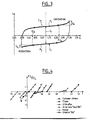
- the anode curve C has a substantially linear central portion, extended towards the higher values by a portion P1 of positive curvature.
- the working electrode 1 For the negative values of the current I, corresponding to the downward half-cycle of the periodic scanning, the working electrode 1 constitutes a cathode.
- the corresponding cathode curve C c has a substantially linear central portion, extended towards the lower potential values by a portion P2 of negative curvature.
- the portions P1 and P2 respectively correspond to the oxidation and reduction phenomena generated when the potential at the electrode goes beyond the limit values for which a faradic current is produced, as explained above with reference to the figure 1 .
- the permissible upper limit of the potential difference of the studied electrode is identified as the value of the potential referenced E la in the figure, corresponding to the change in curvature of the anode curve C a at the junction of the portion P1.
- the excess current I fa which appears beyond the value E la , corresponds to the harmful faradic current described above, and induced by electrochemical reactions.
- the permissible lower limit of the difference in interfacial potential of the studied electrode is determined by the value of the potential, referenced E in Fig lc, corresponding to the change of curvature of the cathodic curve C c at the junction of the portion P2: this excess current I fc which appears beyond the value E lc , corresponds in fact to the faradic current induced by electrochemical reactions, as described with reference to the figure 1 .
- the central linear portions of the curves C a and C c correspond to the alternating circulation of a capacitive current I c between the electrodes successively acting as anode and cathode, as explained with reference to the modeling.
- the allowable range of the .DELTA.E values, having for the terminals E and E c, defines the potential difference value of the material of the working electrode to which it is then ensured, the measurement uncertainty near defined according to the ratio I c / I f , no electrochemical reaction is triggered.
- the values of the inverted voltage potentials are adjusted so that the generated anode and cathode capacitive currents are substantially equivalent.
- An asymmetry in the anodic and cathodic values would lead to not considering the same capacitive load and thus would provide erroneous results.
- the extreme values of the potential difference ranges vary according to the corresponding variation of the currents. anodic and cathodic. Since the latter are linked by the balance of the load balance of the whole, the extreme potentials adjust by themselves on the curve of the currents: the position of their extremities varies in an "opposite" manner and is deduced from the slope of the corresponding anode and cathode currents. To compare the potential difference ranges, it is therefore sufficient to know their amplitudes of variation without having to know the values of their extreme limits.
- Voltamograms such as the one illustrated in figure 3 , have a global form of the hysteresis type which provides access to an accurate determination of the limit interfacial potential difference range ⁇ E l .
- a determination is obtained according to the invention by measuring the ratio between the faradic and capacitive currents ⁇ I f / ⁇ I c , ⁇ I f being the sum of the faradic currents and ⁇ I c , the sum of the constant capacitive currents obtained in the range of use ⁇ E l .
- ⁇ I f and ⁇ I c corresponding to the mathematical integration of the values of the currents intensity over the corresponding potential ranges. They are directly measured, respectively, by the sum of the areas of the surfaces Sf a and Sf c ( figure 3 ), corresponding to the presence of the faradic currents, I fa and I fc , for the potential values beyond the admissible range ⁇ E 1 on the one hand and, on the other hand, to the surface Sc corresponding to the presence of the capacitive current I c in the range ⁇ E l .
- the value of the slopes of the anodic and cathodic faradic current curves presented by the linear parts of the curves represented in FIG. figure 4 can provide a risk criterion: the lower these slopes, the more harmful faradic reaction triggered in case of accidental exceedance of ⁇ E I is limited.
- titanium "T40” undergoes an irreversible passivation wave following the formation of an oxidized insulating layer when the potential exceeds 1.3 volts relative to the reference electrode, while nickel and stainless steel " 316L “undergo a strong dissolution current when their anodic limit potential is exceeded.
- Tables Ia and Ib below show the results obtained respectively for the different bulk materials of electrodes and for materials of the DSA type ("B", “C” in equal proportions of IrO 2 and Ta 2 O 5 , "LZA” coating in IrO 2 and RuO 2 , “Beer” coating in RuO 2 and “PITA” coating in IrO 2 and Ta 2 O 2 ).
- the permissible potential difference range ⁇ E 1 is compared, for each material, with the value of the interfacial potential drop measured directly under ohmic heating conditions. This comparison makes it possible to check if this value is in the admissible range.
- the operating conditions should be adjusted, that is to say to increase the frequency of the applied voltage or to reduce the current density. Such an adjustment decreases the value of the interfacial potential drop.
- this value falls below the value of the allowable range, the material of the electrodes is suitable for ohmic heating, in that a lack of electrochemical reaction is guaranteed.
- an increase in the frequency of the voltage (60 volts effective), for example from 50 Hz to 2500 Hz, allows a decrease in interfacial potential drop of 0.5 V to 1 V depending on the material.
- a reduction of the current density from 5000 A / m 2 to 2500 A / m 2 at 50 Hz allows the DSA "B" to decrease potential drop from 0.65 V to 0.35 V.
- the method consists in measuring the potential difference between an ohmic heating electrode consisting of the material to be tested and a measurement probe whose distance to this electrode varies; then to vary the distance between this electrode and the probe, and to extrapolate at zero distance the regression line obtained from the different potential difference values measured for different distances.
- the value of the ordinate at the origin, divided by two because of the obtaining of the peak-peak measurement (and not of the instantaneous measurement) then represents the value of the interfacial potential difference, characteristic of the material in the ohmic heating conditions.
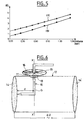
- the figure 5 illustrates two examples of diagram obtained for electrodes of material DSA "B", in a cell containing a solution of corrosive sodium chloride at 20 g per liter, a voltage equal to 60 volts effective being applied to the terminals of the cell, with a current density of 5200 A / m 2 , and a temperature of 60 ° C.
- the extrapolated value ⁇ E i is equal to 1.3 volts measured peak-to-peak, that is to say 0.65 volts maximum in instantaneous value, the applied voltage being respectively that of the sector, of frequency equal to 50 Hz, right (A), and a voltage of frequency equal to 2500 Hz, right (B).
- a significant increase in frequency causes a decrease in interfacial potential drop ⁇ E i , equal to 0.3 V (instantaneous value) in the present case.
- the equipment used to obtain precise measurements is illustrated in figure 6 .
- the probe 10 is a platinum rod with a diameter equal to 1 mm, mounted on a support 11 able to take measurement steps of small amplitude, from a few tenths of a millimeter to less than 0.1 mm, and near the working electrode.
- the probe has a length of 10 cm and is coated with a heat-shrinkable sheath G on the part of the probe immersed in the solution of the cell.
- the rod is mounted on the cell 12 by means of a gland 13, the X'X axis of the probe being at a distance equal to 13 mm from the axis of the electrode 14 tested.
- a silicone seal is added between the probe and the stuffing box.
- the portion of the plunging probe 10 is bent to obtain contact between the refined end of the probe and the test electrode 14. This end is flat and is in the form of a platinum disc of equal diameter at 0.1 mm.
- a protractor 15 is fitted on the main axis X'X of the probe and an index registration system 16 is arranged perpendicularly to the axis X'X of the probe.
- the potential difference between the probe and the test electrode 14 connected to the ground of an oscilloscope (not shown) is measured on a first measurement channel of the oscilloscope, as is the total voltage ⁇ U applied between the electrode. measuring electrode and the other electrode (14 ') of the cell, on a second measuring channel.
- the rotation of the probe around its axis increments the measurement of ten points of measurement of the fall potential.
- the uncertainty of the measurement of the marks of the distance d results from the irregularity of the apparent surface of the platinum probe, this surface varying with the rotation of the vertical axis X'X of the platinum rod. To reduce this uncertainty, the diameter of the platinum probe is minimized to 0.1 mm.
- Table II collates the interfacial potential difference values measured ⁇ E i for different materials constituting the electrode under test, under the conditions previously described (in particular at 50 Hz of frequency and at 5000 A l m 2 of current). This table also shows the values of the permissible interfacial potential ranges ⁇ E 1 of these same materials, as determined by voltammetric analysis, as well as the roughness values.
- DSA-type materials have interfacial tension values ranging from 0.6 to 0.7 volts, within the permissible interfacial tension ranges, ie 1 to 2 volts depending on the DSA material, corresponding to the triggering of electrochemical reactions: these materials are therefore particularly suitable for ohmic heating.
- the massive materials studied they all have an interfacial potential difference value greater than that of their permissible limit range.
- a global parameter integrating the interfacial potential drop ⁇ E i and the interfacial electrical capacitance C i of each material, is hereinafter used to serve as a comparison criterion.
- This global parameter equal to ⁇ E l .C i 2 , is characteristic of the energy of heating a material traversed by an electric current in a solution where Joule effect heat generation occurs.
- Massive materials have global parameters whose values are incommensurate with those of DSA materials, since they differ by a factor of 10 4 to 10 5 .
- the solid material apparently the most efficient bulk materials, namely vitreous carbon has significant uncertainties on the determination of interfacial capacities, greater than 50%. These uncertainties are due to the fact that the interfacial capacitance is sensitive to the surface state of the electrodes, and that this state is very variable for the material in question.
- the global parameter (C i 2 . ⁇ E 1 ) of the DSA materials is calculated from measurements of the permissible interfacial potential range ⁇ E I from an aqueous solution of sodium chloride at 20 g per liter, the values of the capacities C i , determined according to the protocol previously indicated, have particularly stable values at the scanning speed of 100 mV / s.
- the DSA materials are more resistant to an overvoltage at their interface, due to a smaller increase in faradic current, which results in regression slopes of faradic current curves ( ⁇ I f / ⁇ I c ) lower for DSA materials, beyond the limit potential ranges ⁇ E l , as shown in figure 4 .
- the invention is not limited to the applications mentioned and can for example be applied to other techniques in which live materials are in contact with a product, for example in pulsed electric field techniques (CEP abbreviated).
- CEP pulsed electric field techniques
Landscapes
- Life Sciences & Earth Sciences (AREA)
- Engineering & Computer Science (AREA)
- Wood Science & Technology (AREA)
- Zoology (AREA)
- Chemical & Material Sciences (AREA)
- Food Science & Technology (AREA)
- Polymers & Plastics (AREA)
- Investigating Or Analyzing Materials By The Use Of Electric Means (AREA)
- Testing Resistance To Weather, Investigating Materials By Mechanical Methods (AREA)
Claims (8)
- Vorrichtung zum ohmschen Heizen, dadurch gekennzeichnet, dass sie Elektroden aus einem Material vom dimensionsstabilen Anoden(DSA)-Typ beinhaltet, wobei diese Elektroden ein Substrat aus Titan bedeckt von mindestens einer Schicht aus Metalloxiden von Edelmetallen ausgewählt aus Ruthenium, Tantal, Iridium und ihren Mischungen umfassen.
- Vorrichtung nach Anspruch 1, dadurch gekennzeichnet, dass die Oxidschicht mindestens zwei der Metalloxide in Gewichtsanteilen von 25/75 bis 75/25 umfasst.
- Verfahren zur Auswahl von Elektroden für eine Vorrichtung zum ohmschen Heizen nach Anspruch 1 oder 2, dadurch gekennzeichnet, dass es umfasst:Überprüfen, dass der Grenzflächenpotentialabfall (ΔEi) an der Grenzfläche Elektrode-Lösung unter Bedingungen des ohmschen Heizens kleiner ist als der zulässige Potentialbereich der Elektroden (ΔEI), ab dem die energetische Schwelle für die Auslösung von elektrochemischen Reaktionen überschritten ist, wobei dieser Potentialbereich durch Voltammetrie bestimmt wird.
- Verfahren nach Anspruch 3, dadurch gekennzeichnet, dass es umfasst:- Anordnen einer Messsonde (10) in einer ohmschen Heizzelle, wobei diese Zelle eine zu testende Elektrode (14) umfasst,- Variieren des Abstands zwischen der Sonde und der zu testenden Elektrode und- Bestimmen des Grenzflächenpotentialabfalls (ΔEi) durch lineare Extrapolation zum Nullabstand der verschiedenen gemessenen Potentialwerte zwischen der zu testenden Elektrode (14) und der Sonde (10) für die genannten unterschiedlichen Abstände.
- Verfahren nach Anspruch 4, bei dem als Messsonde (10) ein Platinstab mit vertikaler Achse (X'X) und einem Durchmesser von im Wesentlichen gleich oder kleiner als 0,1 mm verwendet wird, wobei dieser Stab an seinem Ende so gebogen ist, dass er mit der zu testenden Elektrode (14) in Kontakt kommt, und ein Maßindex des Rotationswinkels des Stabs um die Achse (X'X), wobei die genannten Abstände zwischen der Sonde und der zu testenden Elektrode aus diesen Winkelmessungen abgeleitet werden.
- Verfahren nach Anspruch 4 oder 5, dadurch gekennzeichnet, dass die Messsonde (10) mit einer wärmeschrumpfbaren Hülse (G) überzogen ist, dass die Sonde auf der Zelle (12) mit Hilfe einer Kabelverbindung (13) angebracht ist, dass eine Silicondichtung zwischen die Sonde und die Kabelverbindung eingesetzt ist, um die Rotation der Sonde im Inneren der Kabelverbindung zu gewährleisten, und dass die Potentialwerte zwischen der zu testenden Elektrode (14) und der Sonde auf einem ersten Kanal eines Oszilloskops gemessen werden, während die angelegte Gesamtspannung (ΔU) zwischen der zu testenden Elektrode (14) und einer weiteren Elektrode (14') der Zelle auf einem zweiten Messkanal des Oszilloskops gemessen wird.
- Verfahren nach einem der Ansprüche 3 bis 6, dadurch gekennzeichnet, dass der zulässige Potentialbereich (ΔEl) durch Ermitteln des Verhältnisses zwischen den Faradayschen Strömen und Kapazitätsströmen ΣIf/ΣIc im gesamten abgetasteten Potentialgebiet an einer Kurve des Faradayschen Stroms erhalten wird, wobei ΣIf die Summe der Faradayschen Ströme ist und ΣIc die Summe der Kapazitätsströme im zulässigen Potentialbereich (ΔEl) ist.
- Verfahren nach Anspruch 7, dadurch gekennzeichnet, dass ein Gefahrenkriterium ab dem zulässigen Potentialbereich (ΔEl) durch die lineare Steigung der Kurve des Faradayschen Stroms (ΣIf/ΣIc) in den Wertebereichen der Potentialabfälle, die über Grenzwerte des zulässigen Potentialbereichs (ΔEl) hinausgehen, definiert ist.
Applications Claiming Priority (2)
| Application Number | Priority Date | Filing Date | Title |
|---|---|---|---|
| FR9803154A FR2776073B1 (fr) | 1998-03-13 | 1998-03-13 | Procede de determination du comportement electrochimique d'un materiau d'electrode et de mesure de chute de potentiel interfaciale electrode/solution dans les conditions de chauffage ohmique, dispositif et applications a cet effet |
| FR9803154 | 1998-03-13 |
Publications (3)
| Publication Number | Publication Date |
|---|---|
| EP0942629A1 EP0942629A1 (de) | 1999-09-15 |
| EP0942629B1 true EP0942629B1 (de) | 2008-11-19 |
| EP0942629B8 EP0942629B8 (de) | 2009-03-18 |
Family
ID=9524053
Family Applications (1)
| Application Number | Title | Priority Date | Filing Date |
|---|---|---|---|
| EP99400623A Expired - Lifetime EP0942629B8 (de) | 1998-03-13 | 1999-03-12 | Verfahren zum Erfassen des elektrochemisches Verhalten eines Elektrodenmaterial und zum Messen des Spannunsabfalls an den Phasengrenzflächen und Verfahren zum ohmischen Heizen |
Country Status (4)
| Country | Link |
|---|---|
| EP (1) | EP0942629B8 (de) |
| DE (1) | DE69939917D1 (de) |
| ES (1) | ES2317687T3 (de) |
| FR (1) | FR2776073B1 (de) |
Families Citing this family (1)
| Publication number | Priority date | Publication date | Assignee | Title |
|---|---|---|---|---|
| IT201900006559A1 (it) | 2019-05-06 | 2020-11-06 | Emmepiemme S R L | Riscaldatore ohmico a campo radiale e elettrodo flottante e relativo metodo di utilizzo. |
Family Cites Families (3)
| Publication number | Priority date | Publication date | Assignee | Title |
|---|---|---|---|---|
| US5235905A (en) * | 1985-05-31 | 1993-08-17 | Foodco Corporation | High pulsed voltage systems for extending the shelf life of pumpable food products |
| DE68925727T2 (de) * | 1989-09-15 | 1996-07-04 | Hewlett Packard Gmbh | Methode zur Bestimmung der optimalen Arbeitsbedingungen in einem elektrochemischen Detektor und elektrochemischer Detektor, diese Methode benutzend |
| CA2132882A1 (en) * | 1993-09-23 | 1995-03-24 | David Reznik | Electroheating of food products using low frequency current |
-
1998
- 1998-03-13 FR FR9803154A patent/FR2776073B1/fr not_active Expired - Fee Related
-
1999
- 1999-03-12 EP EP99400623A patent/EP0942629B8/de not_active Expired - Lifetime
- 1999-03-12 DE DE69939917T patent/DE69939917D1/de not_active Expired - Lifetime
- 1999-03-12 ES ES99400623T patent/ES2317687T3/es not_active Expired - Lifetime
Also Published As
| Publication number | Publication date |
|---|---|
| EP0942629A1 (de) | 1999-09-15 |
| EP0942629B8 (de) | 2009-03-18 |
| DE69939917D1 (de) | 2009-01-02 |
| ES2317687T3 (es) | 2009-04-16 |
| FR2776073A1 (fr) | 1999-09-17 |
| FR2776073B1 (fr) | 2000-08-04 |
Similar Documents
| Publication | Publication Date | Title |
|---|---|---|
| Caldona et al. | Surface electroanalytical approaches to organic polymeric coatings | |
| Zeng et al. | Stripping voltammetric analysis of heavy metals at nitrogen doped diamond‐like carbon film electrodes | |
| WO2010082006A1 (fr) | Micro-capteur réalisé en technologies microsystèmes pour la mesure et/ou la détection de l'encrassement | |
| Hepel et al. | Electrochemical characterization of electrodes with submicrometer dimensions | |
| Lu et al. | The irreversibility of the passive state of carbon steel in the alkaline concrete pore solution under simulated anoxic conditions | |
| Daniele et al. | Recent developments in stripping analysis on microelectrodes | |
| Thierry et al. | Corrosion potential and cathodic reduction efficiency of stainless steel in natural seawater | |
| EP0942629B1 (de) | Verfahren zum Erfassen des elektrochemisches Verhalten eines Elektrodenmaterial und zum Messen des Spannunsabfalls an den Phasengrenzflächen und Verfahren zum ohmischen Heizen | |
| FR2695203A1 (fr) | Détecteur de liquide à thermistance. | |
| Scully et al. | Methods for determining aqueous corrosion reaction rates | |
| FR2535460A1 (fr) | Procede et appareil de controle non destructif de decollement cathodique de revetements de pipe-lines | |
| Hudec et al. | Quantitative coating quality assessment on an offshore platform | |
| Betova et al. | Conduction mechanism in oxide films on ferrous alloys studied by impedance spectroscopy in symmetrical and asymmetrical configurations | |
| Ilic et al. | Silicon corrosion in neutral media: the influence of confined geometries and crevice corrosion in simulated physiological solutions | |
| Trojánek et al. | Limited agreement between the interfacial tension and differential capacity data for the polarised water| 1, 2-dichloroethane interface | |
| EP2212674A1 (de) | Verfahren und vorrichtung zur messung der entwicklung einer ablagerung auf einer oberfläche in kontakt mit einer wässrigen flüssigkeit | |
| EP0330549B1 (de) | Gerät zur kontinuierlichen Messung der Korrosionsschnelligkeit in einer Flüssigkeit, durch ein elektrochemisches Verfahren | |
| EP4065953B1 (de) | Verfahren und vorrichtung zur detektion von korrosion | |
| EP1091209A1 (de) | Elektrochemischer Selbstdiagnosesensor | |
| WO2005062020A1 (fr) | Procede et equipement de detection et de mesure de la corrosion induite par des micro-organismes | |
| Kučera et al. | Evaluation of 08CH18N10T stainless steel corrosion in subcritical water by electrochemical noise analysis | |
| Goldsberry et al. | Applicability of microcapillary electrochemical droplet cell for monitoring microbiologically induced corrosion | |
| Varain | Electrochemical investigation and modeling of ion-and water transport through polymer membranes | |
| Bonilla et al. | Film formation and surface growth on tin electrodes in bicarbonate solutions: an impedance spectroscopy study | |
| Siclovan et al. | High-temperature cyclic voltammetry in non-aqueous solvents |
Legal Events
| Date | Code | Title | Description |
|---|---|---|---|
| PUAI | Public reference made under article 153(3) epc to a published international application that has entered the european phase |
Free format text: ORIGINAL CODE: 0009012 |
|
| AK | Designated contracting states |
Kind code of ref document: A1 Designated state(s): DE ES FR GB GR IE IT NL SE |
|
| AX | Request for extension of the european patent |
Free format text: AL;LT;LV;MK;RO;SI |
|
| RIN1 | Information on inventor provided before grant (corrected) |
Inventor name: HEBERT, SEBASTIEN Inventor name: LAURENT, MARIE-HELENE Inventor name: BERTHOU, MARC |
|
| 17P | Request for examination filed |
Effective date: 20000306 |
|
| AKX | Designation fees paid |
Free format text: DE ES FR GB GR IE IT NL SE |
|
| RAP1 | Party data changed (applicant data changed or rights of an application transferred) |
Owner name: ELECTRICITE DE FRANCE, SOCIETE ANONYME |
|
| 17Q | First examination report despatched |
Effective date: 20051129 |
|
| RIC1 | Information provided on ipc code assigned before grant |
Ipc: H05B 3/12 20060101ALI20071213BHEP Ipc: H05B 3/03 20060101AFI20071213BHEP |
|
| RTI1 | Title (correction) |
Free format text: PROCESS FOR DETERMINING THE ELECTROCHEMICAL BEHAVIOUR OF AN ELECTRODE MATERIAL AND FOR MEASURING THE INTERFACIAL POTENTIAL DROP AND APPARATUS FOR OHMIC HEATING |
|
| GRAP | Despatch of communication of intention to grant a patent |
Free format text: ORIGINAL CODE: EPIDOSNIGR1 |
|
| GRAS | Grant fee paid |
Free format text: ORIGINAL CODE: EPIDOSNIGR3 |
|
| GRAF | Information related to payment of grant fee modified |
Free format text: ORIGINAL CODE: EPIDOSCIGR3 |
|
| GRAL | Information related to payment of fee for publishing/printing deleted |
Free format text: ORIGINAL CODE: EPIDOSDIGR3 |
|
| GRAS | Grant fee paid |
Free format text: ORIGINAL CODE: EPIDOSNIGR3 |
|
| GRAA | (expected) grant |
Free format text: ORIGINAL CODE: 0009210 |
|
| AK | Designated contracting states |
Kind code of ref document: B1 Designated state(s): DE ES FR GB GR IE IT NL SE |
|
| REG | Reference to a national code |
Ref country code: GB Ref legal event code: FG4D Free format text: NOT ENGLISH |
|
| REG | Reference to a national code |
Ref country code: IE Ref legal event code: FG4D Free format text: LANGUAGE OF EP DOCUMENT: FRENCH |
|
| REF | Corresponds to: |
Ref document number: 69939917 Country of ref document: DE Date of ref document: 20090102 Kind code of ref document: P |
|
| RAP2 | Party data changed (patent owner data changed or rights of a patent transferred) |
Owner name: ELECTRICITE DE FRANCE |
|
| REG | Reference to a national code |
Ref country code: GR Ref legal event code: EP Ref document number: 20090400106 Country of ref document: GR |
|
| NLT2 | Nl: modifications (of names), taken from the european patent patent bulletin |
Owner name: ELECTRICITE DE FRANCE Effective date: 20090114 |
|
| REG | Reference to a national code |
Ref country code: SE Ref legal event code: TRGR |
|
| REG | Reference to a national code |
Ref country code: ES Ref legal event code: FG2A Ref document number: 2317687 Country of ref document: ES Kind code of ref document: T3 |
|
| NLXE | Nl: other communications concerning ep-patents (part 3 heading xe) |
Free format text: PAT. BUL. 04/2009, PAGE 519: CORR.: ELECTRICITE DE FRANCE. |
|
| PLBE | No opposition filed within time limit |
Free format text: ORIGINAL CODE: 0009261 |
|
| STAA | Information on the status of an ep patent application or granted ep patent |
Free format text: STATUS: NO OPPOSITION FILED WITHIN TIME LIMIT |
|
| 26N | No opposition filed |
Effective date: 20090820 |
|
| PGFP | Annual fee paid to national office [announced via postgrant information from national office to epo] |
Ref country code: IE Payment date: 20140228 Year of fee payment: 16 Ref country code: DE Payment date: 20140311 Year of fee payment: 16 Ref country code: NL Payment date: 20140224 Year of fee payment: 16 Ref country code: SE Payment date: 20140313 Year of fee payment: 16 |
|
| PGFP | Annual fee paid to national office [announced via postgrant information from national office to epo] |
Ref country code: GR Payment date: 20140218 Year of fee payment: 16 Ref country code: ES Payment date: 20140320 Year of fee payment: 16 Ref country code: IT Payment date: 20140314 Year of fee payment: 16 |
|
| PGFP | Annual fee paid to national office [announced via postgrant information from national office to epo] |
Ref country code: GB Payment date: 20140317 Year of fee payment: 16 |
|
| PGFP | Annual fee paid to national office [announced via postgrant information from national office to epo] |
Ref country code: FR Payment date: 20140331 Year of fee payment: 16 |
|
| REG | Reference to a national code |
Ref country code: DE Ref legal event code: R119 Ref document number: 69939917 Country of ref document: DE |
|
| GBPC | Gb: european patent ceased through non-payment of renewal fee |
Effective date: 20150312 |
|
| PG25 | Lapsed in a contracting state [announced via postgrant information from national office to epo] |
Ref country code: SE Free format text: LAPSE BECAUSE OF NON-PAYMENT OF DUE FEES Effective date: 20150313 |
|
| REG | Reference to a national code |
Ref country code: SE Ref legal event code: EUG |
|
| REG | Reference to a national code |
Ref country code: NL Ref legal event code: MM Effective date: 20150401 |
|
| REG | Reference to a national code |
Ref country code: GR Ref legal event code: ML Ref document number: 20090400106 Country of ref document: GR Effective date: 20151002 |
|
| PG25 | Lapsed in a contracting state [announced via postgrant information from national office to epo] |
Ref country code: IT Free format text: LAPSE BECAUSE OF NON-PAYMENT OF DUE FEES Effective date: 20150312 |
|
| REG | Reference to a national code |
Ref country code: FR Ref legal event code: ST Effective date: 20151130 |
|
| REG | Reference to a national code |
Ref country code: IE Ref legal event code: MM4A |
|
| PG25 | Lapsed in a contracting state [announced via postgrant information from national office to epo] |
Ref country code: DE Free format text: LAPSE BECAUSE OF NON-PAYMENT OF DUE FEES Effective date: 20151001 Ref country code: GR Free format text: LAPSE BECAUSE OF NON-PAYMENT OF DUE FEES Effective date: 20151002 Ref country code: GB Free format text: LAPSE BECAUSE OF NON-PAYMENT OF DUE FEES Effective date: 20150312 Ref country code: IE Free format text: LAPSE BECAUSE OF NON-PAYMENT OF DUE FEES Effective date: 20150312 |
|
| PG25 | Lapsed in a contracting state [announced via postgrant information from national office to epo] |
Ref country code: FR Free format text: LAPSE BECAUSE OF NON-PAYMENT OF DUE FEES Effective date: 20150331 |
|
| REG | Reference to a national code |
Ref country code: ES Ref legal event code: FD2A Effective date: 20170428 |
|
| PG25 | Lapsed in a contracting state [announced via postgrant information from national office to epo] |
Ref country code: NL Free format text: LAPSE BECAUSE OF NON-PAYMENT OF DUE FEES Effective date: 20150401 Ref country code: ES Free format text: LAPSE BECAUSE OF NON-PAYMENT OF DUE FEES Effective date: 20150313 |
|
| PG25 | Lapsed in a contracting state [announced via postgrant information from national office to epo] |
Ref country code: ES Free format text: LAPSE BECAUSE OF NON-PAYMENT OF DUE FEES Effective date: 20160313 |