EP0942637A2 - Appareillage pour systèmes d'automatisation à commande électronique - Google Patents
Appareillage pour systèmes d'automatisation à commande électronique Download PDFInfo
- Publication number
- EP0942637A2 EP0942637A2 EP99102485A EP99102485A EP0942637A2 EP 0942637 A2 EP0942637 A2 EP 0942637A2 EP 99102485 A EP99102485 A EP 99102485A EP 99102485 A EP99102485 A EP 99102485A EP 0942637 A2 EP0942637 A2 EP 0942637A2
- Authority
- EP
- European Patent Office
- Prior art keywords
- securing element
- control system
- slot
- connection block
- shaped guides
- Prior art date
- Legal status (The legal status is an assumption and is not a legal conclusion. Google has not performed a legal analysis and makes no representation as to the accuracy of the status listed.)
- Granted
Links
- 230000000903 blocking effect Effects 0.000 claims description 8
- 239000004020 conductor Substances 0.000 claims description 3
- 239000000463 material Substances 0.000 claims description 2
- 230000006978 adaptation Effects 0.000 description 1
- 238000011161 development Methods 0.000 description 1
- 230000018109 developmental process Effects 0.000 description 1
- 239000003999 initiator Substances 0.000 description 1
- 238000003780 insertion Methods 0.000 description 1
- 230000037431 insertion Effects 0.000 description 1
- 238000009434 installation Methods 0.000 description 1
- 239000011810 insulating material Substances 0.000 description 1
- 238000000034 method Methods 0.000 description 1
- 230000001681 protective effect Effects 0.000 description 1
- 230000000284 resting effect Effects 0.000 description 1
Images


Classifications
-
- H—ELECTRICITY
- H05—ELECTRIC TECHNIQUES NOT OTHERWISE PROVIDED FOR
- H05K—PRINTED CIRCUITS; CASINGS OR CONSTRUCTIONAL DETAILS OF ELECTRIC APPARATUS; MANUFACTURE OF ASSEMBLAGES OF ELECTRICAL COMPONENTS
- H05K7/00—Constructional details common to different types of electric apparatus
- H05K7/14—Mounting supporting structure in casing or on frame or rack
- H05K7/1462—Mounting supporting structure in casing or on frame or rack for programmable logic controllers [PLC] for automation or industrial process control
- H05K7/1474—Mounting of modules, e.g. on a base or rail or wall
-
- H—ELECTRICITY
- H01—ELECTRIC ELEMENTS
- H01R—ELECTRICALLY-CONDUCTIVE CONNECTIONS; STRUCTURAL ASSOCIATIONS OF A PLURALITY OF MUTUALLY-INSULATED ELECTRICAL CONNECTING ELEMENTS; COUPLING DEVICES; CURRENT COLLECTORS
- H01R9/00—Structural associations of a plurality of mutually-insulated electrical connecting elements, e.g. terminal strips or terminal blocks; Terminals or binding posts mounted upon a base or in a case; Bases therefor
- H01R9/22—Bases, e.g. strip, block, panel
- H01R9/24—Terminal blocks
- H01R9/26—Clip-on terminal blocks for side-by-side rail- or strip-mounting
- H01R9/2608—Fastening means for mounting on support rail or strip
-
- H—ELECTRICITY
- H02—GENERATION; CONVERSION OR DISTRIBUTION OF ELECTRIC POWER
- H02B—BOARDS, SUBSTATIONS OR SWITCHING ARRANGEMENTS FOR THE SUPPLY OR DISTRIBUTION OF ELECTRIC POWER
- H02B1/00—Frameworks, boards, panels, desks, casings; Details of substations or switching arrangements
- H02B1/015—Boards, panels, desks; Parts thereof or accessories therefor
- H02B1/04—Mounting thereon of switches or of other devices in general, the switch or device having, or being without, casing
- H02B1/041—Mechanical coupling for side-by-side mounted apparatus
Definitions
- the present invention relates to a control system for electronic Control and automation systems according to the preamble of claim 1.
- Such control systems are used to control z. B. for a machine or a production plant with the installed initiators distributed in the periphery, To electrically connect actuators, field devices or the like.
- the present invention is therefore based on the object of a control system of the generic type to create that in a simple manner without increasing the actuating force a secure mechanical connection between the terminal block and the electronics module guaranteed.
- the solution according to the invention results itself from claim 1.
- the use of a separate securing element as a result extremely easy to use. A structural complication does not occur because the separate securing element with the existing T-slot Guides cooperates. With the securing element one can reliable blocking of the inserted electronic module even for rough workshop operations guarantee.
- the securing element consists of one piece Basic body with two slide elements slidably guided therein. In the overall view is sufficient after inserting the securing element and inserting it of the electronics module thus a short, easy to carry out shift of the Slider elements in the blocking position over the two T-slot counterparts of the Electronics module.
- the securing element itself by means of locking hooks in corresponding locking recesses, which are in the shape of the T-slot Guided tours are provided.
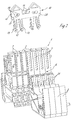
- connection block 1 in the illustrated embodiment, which consists of a Baying of connecting disks 2 is composed.
- the connecting washers 2 are identical in their outer contours, otherwise electrotechnically depending on the application functionally equipped, so that for example in such a connection block 1 at least one protective conductor washer, one feed washer and there are a number of supply / signal conductor disks.
- the single ones Terminal washers 2 have at the lower end of their housing made of insulating material a locking contour 3, 4, with which the connection block 1 in switchgear Standard rails can be snapped on.
- the control system also includes an electronic module 5 that mechanically the connection block 1 is to be connected by a plug connection.
- the connecting washers 2 form a receiving space 6 in their connection in the connection block 1, in which the electronics module 5 can be inserted vertically.
- On one boundary surface of the receiving space 6 are each on the connecting disks 2 to the Receiving space 6 formed T-groove-shaped guides 7. As shown in the Exemplary embodiment of the connection block 1 consists of seven connection disks 2, there are therefore seven T-shaped guides 7.
- two T-slot counterparts 9 are provided, in adaptation to this Embodiment of a connection block 1 at such a distance from one another, that when you vertically insert the housing 8 of the electronic module 5 in the receiving space 6 in the two outer T-groove guides 7 enter.
- a separate securing element 10 is now provided, which in the existing T-slot-shaped guides 7 can be fixed and the means for blocking of the inserted electronics module 5 in the pull-out direction.
- illustrated embodiment is a fuse element 10 provided that a one-piece base body 11 with two down protruding locking leg pairs 12, the locking legs 12 each after have locking hooks 13 projecting outside.
- the outer contour of the base body 11 of the Fuse element 10 is dimensioned so that the fuse element 10 is accurate between the two T-slot counterparts 9 of the housing 8 of the electronics module 5 fits.
- the arrangement is also such that the pairs of locking legs 12 with the Latching hooks 13 leaving the T-slot-shaped on the outside Guides 7 in the two inwardly adjacent T-slot-shaped Guides 7 can be inserted.
- the T-slots are in the material webs Guides 7 at a corresponding point in their longitudinal course locking recesses 14 provided, into which the locking hooks 13 of the locking leg pairs 12 after insertion of the securing element 10 can snap into place, so that the securing element 10 thereafter has a firm, captive hold in the connection block 1.
- each slide elements 16 can be inserted, as in Figure 1 in each three different phases is illustrated.
- Both slide elements 16 each have locking cams 17 on their two sides on and in the one-piece base body 11 are on both sides for each of the slide elements 16 provided on both sides locking hole pairs 18, the locking hole pairs 18 each connected by a narrow passage channel 19 are.
- the locking bore pairs 18 allow in connection with the locking cams 17 a latching of the two functional positions still to be described the slide elements 16 in the base body 11 of the securing element 10.
- the slide elements 16 stop pieces 20, the among other things, define the fully inserted position of the slide elements 16, as shown in Figure 1.
- the fully assembled securing element is in the T-shaped guides 7 of the Terminal block 1 used so that the two outer T-shaped grooves Guides 7 remain free.
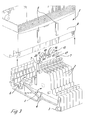
- the slide elements 16 are in the complete inserted a functional position (see Figure 3).
- the securing element 10 is captive with the locking hooks 13 of its locking legs 12 in the connection block fixed at a functional position.
- the electronics module 5 with its housing 8 is inserted into the receiving space 6 of the terminal block 1 used, its two T-slot counterparts 9 in the enter the two outer T-slot guides 7.
- This assembly process is ensures that the outer contour of the securing element 10 between the two T-slot counterparts fit (see Figure 3).
- the two slide elements 16 moved in opposite directions to each other so that they with their outer Ends and in particular the stop pieces 20 then over the two T-slot counterparts 9 of the inserted electronic module 5 and thus grip it in the Block the inserted position in the pull-out direction so that the electronics module 5 is held captive in connection block 1 even in the harshest workshop operation.
- This functional position of the slide elements 16 are in turn in the corresponding Locking bores 18 of the locking bore pairs locked by means of their locking cams 17.
- the two slide elements are sufficient 16 from the blocking position into the interior of the base body 11 of the securing element to move so that they again assume the position shown in Figure 3.
- the electronics module 5 can then easily be removed upwards become.
- connection block 1 there are still 6 in the area of the receiving space the usual block 21 of the connection block 1 on the connection disks 2, those located in a housing wall 22 of the electronics module housing 8 Locking recesses (not shown) for locking the electronic module 5 in the receiving space 6 of the connection block 1 cooperate.
- Locking recesses (not shown) for locking the electronic module 5 in the receiving space 6 of the connection block 1 cooperate.
- the blocking function of the securing element 10 can be thought of such To waive locking. The force required for the plug connection between the Electronics module 5 and the connection block 1 can thereby be further reduced become.
Landscapes
- Engineering & Computer Science (AREA)
- Automation & Control Theory (AREA)
- Microelectronics & Electronic Packaging (AREA)
- Connector Housings Or Holding Contact Members (AREA)
- Casings For Electric Apparatus (AREA)
- Mounting Components In General For Electric Apparatus (AREA)
- Selective Calling Equipment (AREA)
- Programmable Controllers (AREA)
Applications Claiming Priority (2)
| Application Number | Priority Date | Filing Date | Title |
|---|---|---|---|
| DE29804284U DE29804284U1 (de) | 1998-03-11 | 1998-03-11 | Steuerungsanlage für elektronische Steuerungs- und Automatisierungssysteme |
| DE29804284U | 1998-03-11 |
Publications (3)
| Publication Number | Publication Date |
|---|---|
| EP0942637A2 true EP0942637A2 (fr) | 1999-09-15 |
| EP0942637A3 EP0942637A3 (fr) | 1999-10-27 |
| EP0942637B1 EP0942637B1 (fr) | 2004-10-20 |
Family
ID=8053936
Family Applications (1)
| Application Number | Title | Priority Date | Filing Date |
|---|---|---|---|
| EP99102485A Expired - Lifetime EP0942637B1 (fr) | 1998-03-11 | 1999-02-10 | Appareillage pour systèmes d'automatisation à commande électronique |
Country Status (3)
| Country | Link |
|---|---|
| US (1) | US6027380A (fr) |
| EP (1) | EP0942637B1 (fr) |
| DE (2) | DE29804284U1 (fr) |
Cited By (1)
| Publication number | Priority date | Publication date | Assignee | Title |
|---|---|---|---|---|
| WO2006102955A1 (fr) | 2005-04-01 | 2006-10-05 | Sew-Eurodrive Gmbh & Co. Kg | Dispositif |
Families Citing this family (19)
| Publication number | Priority date | Publication date | Assignee | Title |
|---|---|---|---|---|
| DE19860961C1 (de) * | 1998-10-09 | 2001-09-06 | Aeg Niederspannungstech Gmbh | Elektrisches Gerät mit einer Verbindungseinrichtung zur Verbindung mit einem zweiten elektrischen Gerät |
| DE19964156B4 (de) * | 1999-01-25 | 2004-07-15 | Weidmüller Interface Gmbh & Co. | Elektrisches Gerät |
| US6361374B1 (en) * | 2000-02-29 | 2002-03-26 | Molex Incorporated | Connector module retainer especially suitable for wafer connectors and connector assembly utilizing same |
| US6273762B1 (en) * | 1999-11-03 | 2001-08-14 | Molex Incorporated | Connector module retainer especially suitable for wafer connectors and connector assembly utilizing same |
| EP1317783B1 (fr) * | 2000-09-12 | 2006-10-18 | Tyco Electronics AMP GmbH | Systeme de raccord modulaire pour applications ethernet dans le secteur industriel |
| DE10146503A1 (de) * | 2001-09-21 | 2003-04-10 | Abb Patent Gmbh | Elektrische Installationsverteilung |
| EP1625586A4 (fr) * | 2003-05-20 | 2010-05-12 | Enter Tech Co Ltd | Systeme de karaoke portable |
| FR2874132B1 (fr) * | 2004-08-03 | 2012-06-01 | Infra Sa | Element de jonction pour assembler deux supports de connecteurs adjacents et ensemble de support de connecteur comprenant un tel element de jonction |
| DE102005003199A1 (de) * | 2004-08-24 | 2006-03-02 | Weidmüller Interface GmbH & Co. KG | Montage- und Anschluß-System für elektrische Geräte |
| DE102005040657A1 (de) * | 2005-08-26 | 2007-03-15 | Phoenix Contact Gmbh & Co. Kg | Elektrische Anschlussklemme |
| DE202006017882U1 (de) * | 2006-11-22 | 2007-03-01 | Cedes Ag | Steckmodul |
| EP2128942B1 (fr) * | 2008-05-28 | 2011-11-23 | EATON Industries Manufacturing GmbH | Système de bus modulaire et corps de module correspondant |
| DE102015205427B4 (de) | 2015-03-25 | 2025-03-27 | Shanghai Vehinfo Technologies Co., Ltd. | Verbindungselement zum mechanischen Verbinden von Elektronikgehäusen |
| US9336977B1 (en) | 2015-04-03 | 2016-05-10 | Eaton Corporation | Electrical switching apparatus and secondary disconnect assembly with terminal retention and correction features therefor |
| US9576762B2 (en) | 2015-04-03 | 2017-02-21 | Eaton Corporation | Electrical switching apparatus and secondary disconnect assembly with error-proofing features therefor |
| US9570261B2 (en) | 2015-04-03 | 2017-02-14 | Eaton Corporation | Electrical switching apparatus and secondary disconnect assembly with contact alignment features therefor |
| US9396889B1 (en) | 2015-04-03 | 2016-07-19 | Eaton Corporation | Electrical switching apparatus and secondary disconnect assembly with cradle assembly alignment and positioning features therefor |
| US10483663B2 (en) * | 2017-11-09 | 2019-11-19 | Rockwell Automation Asia Pacific Business Center Pte. Ltd. | Terminal block with retention features for a removable I/O module |
| DE202019103271U1 (de) * | 2019-06-11 | 2020-09-16 | Wago Verwaltungsgesellschaft Mbh | Leiteranschlussklemme, Sortiment aus wenigstens einem Basismodul und unterschiedlich ausgebildeten Leiteranschlussmodulen einer Leiteranschlussklemme und Leiteranschlussklemmenblock |
Family Cites Families (11)
| Publication number | Priority date | Publication date | Assignee | Title |
|---|---|---|---|---|
| DE1790244A1 (de) * | 1964-02-29 | 1971-12-30 | Standard Elek K Lorenz Ag | Sperrvorrichtung fuer eine Anzahl in Baugruppentraeger eingesteckte Einschuebe |
| DE3527677A1 (de) * | 1985-08-01 | 1987-02-12 | Siemens Ag | Fuehrungseinrichtung fuer elektrische geraete |
| DE4403585A1 (de) * | 1994-02-05 | 1995-08-10 | Licentia Gmbh | Kombination von zwei Schaltgeräten oder anderen elektrischen Reiheneinbaugeräten |
| DE4410817C1 (de) * | 1994-03-22 | 1995-02-16 | Imc Messysteme Gmbh | Stromerfassungseinrichtung |
| DE9406386U1 (de) * | 1994-04-16 | 1994-06-30 | Klöckner-Moeller GmbH, 53115 Bonn | Befestigungsplatte zum Aufrasten eines darauf montierten Niederspannungsschaltgerätes auf eine Hutschiene |
| DE4438805C1 (de) * | 1994-10-31 | 1996-03-07 | Weidmueller Interface | Feldbusanschlußmodul |
| DE4438800C1 (de) * | 1994-10-31 | 1996-01-18 | Weidmueller Interface | Anschlußklemmenblock mit Elektronikmodul |
| DE4438804C1 (de) * | 1994-10-31 | 1996-03-28 | Weidmueller Interface | Modulare Steuerungsanlage mit Busleiter z. B. zur Gebäudeautomatisierung |
| DE4438806C1 (de) * | 1994-10-31 | 1996-03-21 | Weidmueller Interface | Modulare Steuerungsanlage mit Busleiter |
| DE29606007U1 (de) * | 1996-03-20 | 1996-06-20 | Hartmann & Braun Ag, 60487 Frankfurt | Steckbares Modulgehäuse mit einem aufreihbaren Sockel für Normschienenmontage |
| US5727964A (en) * | 1996-04-30 | 1998-03-17 | The Whitaker Corporation | System for remote latching and delatching |
-
1998
- 1998-03-11 DE DE29804284U patent/DE29804284U1/de not_active Expired - Lifetime
-
1999
- 1999-02-10 EP EP99102485A patent/EP0942637B1/fr not_active Expired - Lifetime
- 1999-02-10 DE DE59910873T patent/DE59910873D1/de not_active Expired - Lifetime
- 1999-03-10 US US09/265,419 patent/US6027380A/en not_active Expired - Fee Related
Cited By (1)
| Publication number | Priority date | Publication date | Assignee | Title |
|---|---|---|---|---|
| WO2006102955A1 (fr) | 2005-04-01 | 2006-10-05 | Sew-Eurodrive Gmbh & Co. Kg | Dispositif |
Also Published As
| Publication number | Publication date |
|---|---|
| US6027380A (en) | 2000-02-22 |
| DE29804284U1 (de) | 1998-05-07 |
| DE59910873D1 (de) | 2004-11-25 |
| EP0942637B1 (fr) | 2004-10-20 |
| EP0942637A3 (fr) | 1999-10-27 |
Similar Documents
| Publication | Publication Date | Title |
|---|---|---|
| EP0942637B1 (fr) | Appareillage pour systèmes d'automatisation à commande électronique | |
| DE4438801C1 (de) | Modulare Steuerungsanlage | |
| EP2917974B9 (fr) | Connecteur modulaire | |
| EP2255409B1 (fr) | Pont de commutation et unité composée d'au moins deux blocs de jonction électriques et d'un pont de commutation | |
| EP0709917B1 (fr) | Bloc de connexion avec module électronique | |
| EP3482410B1 (fr) | Relais électromécanique, bloc de jonction et ensemble relais électromécanique | |
| EP3474646B1 (fr) | Boîtier de rail de guidage, module électronique doté d'un boîtier de rail de guidage et système, en particulier un système de commande, doté d'une pluralité de modules électroniques | |
| EP2715871B1 (fr) | Dispositif de contrôle et de connexion | |
| EP1191643B1 (fr) | Boítier pour un dispositif électronique | |
| EP4039070B1 (fr) | Dispositif électronique comprenant un dispositif de verrouillage | |
| EP0865105B1 (fr) | Douille de connexion électrique avec ressort de contact et douille utilisable comme contact terminal | |
| DE2544936A1 (de) | Verbinder fuer gedruckte schaltungen | |
| EP0760539A2 (fr) | Barrette à borne avec barre omnibus | |
| DE19706636A1 (de) | Elektrische Anschlußvorrichtung für in einer Reihe angeordnete Verbraucher, insbesondere Magnetventile | |
| DE19638144A1 (de) | Hilfsschalter | |
| EP0391049B1 (fr) | Interrupteur, en particulier interrupteur d'appareil | |
| WO2023180170A1 (fr) | Unité fonctionnelle comprenant un bornier électrique et une fiche | |
| EP0453918B1 (fr) | Module auxiliaire pour appareil de commutation électromagnétique | |
| EP1816707A2 (fr) | Plaque à bornes pour des appareils notamment pour des fiches | |
| DE19530335B4 (de) | Steckeranordnung | |
| DE19709198A1 (de) | Steckeranordnung mit einem Betätigungsschieber | |
| BE1032147B1 (de) | Sensor-Aktor-Verteiler | |
| CH653181A5 (en) | Electrical connecting element | |
| DE19902811C1 (de) | Kodiervorrichtung und Kodierverfahren zur Kodierung eines elektrischen Gerätes | |
| EP1038109A1 (fr) | Appareil electrique a clip de raccordement et logement de clip de raccordement pour le raccordement a un deuxieme appareil electrique |
Legal Events
| Date | Code | Title | Description |
|---|---|---|---|
| PUAI | Public reference made under article 153(3) epc to a published international application that has entered the european phase |
Free format text: ORIGINAL CODE: 0009012 |
|
| PUAL | Search report despatched |
Free format text: ORIGINAL CODE: 0009013 |
|
| AK | Designated contracting states |
Kind code of ref document: A2 Designated state(s): CH DE FR GB IT LI |
|
| AX | Request for extension of the european patent |
Free format text: AL;LT;LV;MK;RO;SI |
|
| AK | Designated contracting states |
Kind code of ref document: A3 Designated state(s): AT BE CH CY DE DK ES FI FR GB GR IE IT LI LU MC NL PT SE |
|
| AX | Request for extension of the european patent |
Free format text: AL;LT;LV;MK;RO;SI |
|
| 17P | Request for examination filed |
Effective date: 19991006 |
|
| AKX | Designation fees paid |
Free format text: CH DE FR GB IT LI |
|
| GRAP | Despatch of communication of intention to grant a patent |
Free format text: ORIGINAL CODE: EPIDOSNIGR1 |
|
| GRAS | Grant fee paid |
Free format text: ORIGINAL CODE: EPIDOSNIGR3 |
|
| GRAA | (expected) grant |
Free format text: ORIGINAL CODE: 0009210 |
|
| AK | Designated contracting states |
Kind code of ref document: B1 Designated state(s): CH DE FR GB IT LI |
|
| REG | Reference to a national code |
Ref country code: GB Ref legal event code: FG4D Free format text: NOT ENGLISH |
|
| REG | Reference to a national code |
Ref country code: CH Ref legal event code: NV Representative=s name: ISLER & PEDRAZZINI AG Ref country code: CH Ref legal event code: EP |
|
| REF | Corresponds to: |
Ref document number: 59910873 Country of ref document: DE Date of ref document: 20041125 Kind code of ref document: P |
|
| GBT | Gb: translation of ep patent filed (gb section 77(6)(a)/1977) |
Effective date: 20041208 |
|
| PLBE | No opposition filed within time limit |
Free format text: ORIGINAL CODE: 0009261 |
|
| STAA | Information on the status of an ep patent application or granted ep patent |
Free format text: STATUS: NO OPPOSITION FILED WITHIN TIME LIMIT |
|
| 26N | No opposition filed |
Effective date: 20050721 |
|
| ET | Fr: translation filed | ||
| REG | Reference to a national code |
Ref country code: CH Ref legal event code: PCAR Free format text: ISLER & PEDRAZZINI AG;POSTFACH 1772;8027 ZUERICH (CH) |
|
| PGFP | Annual fee paid to national office [announced via postgrant information from national office to epo] |
Ref country code: FR Payment date: 20100226 Year of fee payment: 12 |
|
| PGFP | Annual fee paid to national office [announced via postgrant information from national office to epo] |
Ref country code: GB Payment date: 20100218 Year of fee payment: 12 |
|
| GBPC | Gb: european patent ceased through non-payment of renewal fee |
Effective date: 20110210 |
|
| REG | Reference to a national code |
Ref country code: FR Ref legal event code: ST Effective date: 20111102 |
|
| PG25 | Lapsed in a contracting state [announced via postgrant information from national office to epo] |
Ref country code: FR Free format text: LAPSE BECAUSE OF NON-PAYMENT OF DUE FEES Effective date: 20110228 |
|
| PG25 | Lapsed in a contracting state [announced via postgrant information from national office to epo] |
Ref country code: GB Free format text: LAPSE BECAUSE OF NON-PAYMENT OF DUE FEES Effective date: 20110210 |
|
| PGFP | Annual fee paid to national office [announced via postgrant information from national office to epo] |
Ref country code: CH Payment date: 20140218 Year of fee payment: 16 |
|
| PGFP | Annual fee paid to national office [announced via postgrant information from national office to epo] |
Ref country code: IT Payment date: 20150223 Year of fee payment: 17 |
|
| REG | Reference to a national code |
Ref country code: CH Ref legal event code: PL |
|
| PG25 | Lapsed in a contracting state [announced via postgrant information from national office to epo] |
Ref country code: CH Free format text: LAPSE BECAUSE OF NON-PAYMENT OF DUE FEES Effective date: 20150228 Ref country code: LI Free format text: LAPSE BECAUSE OF NON-PAYMENT OF DUE FEES Effective date: 20150228 |
|
| PGFP | Annual fee paid to national office [announced via postgrant information from national office to epo] |
Ref country code: DE Payment date: 20160218 Year of fee payment: 18 |
|
| PG25 | Lapsed in a contracting state [announced via postgrant information from national office to epo] |
Ref country code: IT Free format text: LAPSE BECAUSE OF NON-PAYMENT OF DUE FEES Effective date: 20160210 |
|
| REG | Reference to a national code |
Ref country code: DE Ref legal event code: R119 Ref document number: 59910873 Country of ref document: DE |
|
| PG25 | Lapsed in a contracting state [announced via postgrant information from national office to epo] |
Ref country code: DE Free format text: LAPSE BECAUSE OF NON-PAYMENT OF DUE FEES Effective date: 20170901 |