EP0942764B1 - Vorrichtung zur bestimmung des gasvolumens sowie volumenänderungen in einem narkosesystem - Google Patents
Vorrichtung zur bestimmung des gasvolumens sowie volumenänderungen in einem narkosesystem Download PDFInfo
- Publication number
- EP0942764B1 EP0942764B1 EP98936605A EP98936605A EP0942764B1 EP 0942764 B1 EP0942764 B1 EP 0942764B1 EP 98936605 A EP98936605 A EP 98936605A EP 98936605 A EP98936605 A EP 98936605A EP 0942764 B1 EP0942764 B1 EP 0942764B1
- Authority
- EP
- European Patent Office
- Prior art keywords
- bellows
- gas
- sensor
- circuit
- anaesthesia
- Prior art date
- Legal status (The legal status is an assumption and is not a legal conclusion. Google has not performed a legal analysis and makes no representation as to the accuracy of the status listed.)
- Expired - Lifetime
Links
- 206010002091 Anaesthesia Diseases 0.000 title claims description 84
- 238000001949 anaesthesia Methods 0.000 title claims description 84
- 230000037005 anaesthesia Effects 0.000 title claims description 84
- 239000007789 gas Substances 0.000 claims description 112
- QVGXLLKOCUKJST-UHFFFAOYSA-N atomic oxygen Chemical compound [O] QVGXLLKOCUKJST-UHFFFAOYSA-N 0.000 claims description 25
- 239000001301 oxygen Substances 0.000 claims description 25
- 229910052760 oxygen Inorganic materials 0.000 claims description 25
- 229940124326 anaesthetic agent Drugs 0.000 claims description 8
- 239000003193 general anesthetic agent Substances 0.000 claims description 8
- 230000006835 compression Effects 0.000 claims 2
- 238000007906 compression Methods 0.000 claims 2
- MYMOFIZGZYHOMD-UHFFFAOYSA-N Dioxygen Chemical compound O=O MYMOFIZGZYHOMD-UHFFFAOYSA-N 0.000 claims 1
- 229910001882 dioxygen Inorganic materials 0.000 claims 1
- 239000012530 fluid Substances 0.000 claims 1
- 230000000241 respiratory effect Effects 0.000 description 31
- GQPLMRYTRLFLPF-UHFFFAOYSA-N Nitrous Oxide Chemical compound [O-][N+]#N GQPLMRYTRLFLPF-UHFFFAOYSA-N 0.000 description 28
- 239000001272 nitrous oxide Substances 0.000 description 14
- CURLTUGMZLYLDI-UHFFFAOYSA-N Carbon dioxide Chemical compound O=C=O CURLTUGMZLYLDI-UHFFFAOYSA-N 0.000 description 12
- 239000000203 mixture Substances 0.000 description 12
- 229910002092 carbon dioxide Inorganic materials 0.000 description 9
- 239000001569 carbon dioxide Substances 0.000 description 9
- 239000004020 conductor Substances 0.000 description 9
- 230000007423 decrease Effects 0.000 description 8
- 230000003247 decreasing effect Effects 0.000 description 7
- 230000029058 respiratory gaseous exchange Effects 0.000 description 7
- 239000006096 absorbing agent Substances 0.000 description 5
- 239000012159 carrier gas Substances 0.000 description 5
- 238000012986 modification Methods 0.000 description 4
- 230000004048 modification Effects 0.000 description 4
- 238000000034 method Methods 0.000 description 3
- 230000002000 scavenging effect Effects 0.000 description 3
- 230000002745 absorbent Effects 0.000 description 2
- 239000002250 absorbent Substances 0.000 description 2
- 230000004075 alteration Effects 0.000 description 2
- 239000003795 chemical substances by application Substances 0.000 description 2
- 230000001276 controlling effect Effects 0.000 description 2
- 238000012423 maintenance Methods 0.000 description 2
- 238000012544 monitoring process Methods 0.000 description 2
- 230000036284 oxygen consumption Effects 0.000 description 2
- 239000006200 vaporizer Substances 0.000 description 2
- 241000894006 Bacteria Species 0.000 description 1
- 235000014676 Phragmites communis Nutrition 0.000 description 1
- CDBYLPFSWZWCQE-UHFFFAOYSA-L Sodium Carbonate Chemical compound [Na+].[Na+].[O-]C([O-])=O CDBYLPFSWZWCQE-UHFFFAOYSA-L 0.000 description 1
- 239000003570 air Substances 0.000 description 1
- 230000008859 change Effects 0.000 description 1
- 238000010276 construction Methods 0.000 description 1
- 230000008602 contraction Effects 0.000 description 1
- 238000007599 discharging Methods 0.000 description 1
- 238000003912 environmental pollution Methods 0.000 description 1
- 210000004072 lung Anatomy 0.000 description 1
- 239000000463 material Substances 0.000 description 1
- 230000003287 optical effect Effects 0.000 description 1
- 230000004962 physiological condition Effects 0.000 description 1
- 239000004033 plastic Substances 0.000 description 1
- 230000008569 process Effects 0.000 description 1
- 230000001105 regulatory effect Effects 0.000 description 1
- 230000036387 respiratory rate Effects 0.000 description 1
- 230000004044 response Effects 0.000 description 1
- 230000000717 retained effect Effects 0.000 description 1
- 230000000630 rising effect Effects 0.000 description 1
- HUAUNKAZQWMVFY-UHFFFAOYSA-M sodium;oxocalcium;hydroxide Chemical compound [OH-].[Na+].[Ca]=O HUAUNKAZQWMVFY-UHFFFAOYSA-M 0.000 description 1
- 238000001228 spectrum Methods 0.000 description 1
- 238000011144 upstream manufacturing Methods 0.000 description 1
- 230000000007 visual effect Effects 0.000 description 1
Images


Classifications
-
- A—HUMAN NECESSITIES
- A61—MEDICAL OR VETERINARY SCIENCE; HYGIENE
- A61M—DEVICES FOR INTRODUCING MEDIA INTO, OR ONTO, THE BODY; DEVICES FOR TRANSDUCING BODY MEDIA OR FOR TAKING MEDIA FROM THE BODY; DEVICES FOR PRODUCING OR ENDING SLEEP OR STUPOR
- A61M16/00—Devices for influencing the respiratory system of patients by gas treatment, e.g. ventilators; Tracheal tubes
- A61M16/0057—Pumps therefor
- A61M16/0075—Bellows-type
-
- A—HUMAN NECESSITIES
- A61—MEDICAL OR VETERINARY SCIENCE; HYGIENE
- A61M—DEVICES FOR INTRODUCING MEDIA INTO, OR ONTO, THE BODY; DEVICES FOR TRANSDUCING BODY MEDIA OR FOR TAKING MEDIA FROM THE BODY; DEVICES FOR PRODUCING OR ENDING SLEEP OR STUPOR
- A61M16/00—Devices for influencing the respiratory system of patients by gas treatment, e.g. ventilators; Tracheal tubes
- A61M16/0057—Pumps therefor
- A61M16/0081—Bag or bellow in a bottle
-
- A—HUMAN NECESSITIES
- A61—MEDICAL OR VETERINARY SCIENCE; HYGIENE
- A61M—DEVICES FOR INTRODUCING MEDIA INTO, OR ONTO, THE BODY; DEVICES FOR TRANSDUCING BODY MEDIA OR FOR TAKING MEDIA FROM THE BODY; DEVICES FOR PRODUCING OR ENDING SLEEP OR STUPOR
- A61M16/00—Devices for influencing the respiratory system of patients by gas treatment, e.g. ventilators; Tracheal tubes
- A61M16/01—Devices for influencing the respiratory system of patients by gas treatment, e.g. ventilators; Tracheal tubes specially adapted for anaesthetising
-
- A—HUMAN NECESSITIES
- A61—MEDICAL OR VETERINARY SCIENCE; HYGIENE
- A61M—DEVICES FOR INTRODUCING MEDIA INTO, OR ONTO, THE BODY; DEVICES FOR TRANSDUCING BODY MEDIA OR FOR TAKING MEDIA FROM THE BODY; DEVICES FOR PRODUCING OR ENDING SLEEP OR STUPOR
- A61M16/00—Devices for influencing the respiratory system of patients by gas treatment, e.g. ventilators; Tracheal tubes
- A61M16/08—Bellows; Connecting tubes ; Water traps; Patient circuits
- A61M16/0816—Joints or connectors
- A61M16/0833—T- or Y-type connectors, e.g. Y-piece
-
- A—HUMAN NECESSITIES
- A61—MEDICAL OR VETERINARY SCIENCE; HYGIENE
- A61M—DEVICES FOR INTRODUCING MEDIA INTO, OR ONTO, THE BODY; DEVICES FOR TRANSDUCING BODY MEDIA OR FOR TAKING MEDIA FROM THE BODY; DEVICES FOR PRODUCING OR ENDING SLEEP OR STUPOR
- A61M16/00—Devices for influencing the respiratory system of patients by gas treatment, e.g. ventilators; Tracheal tubes
- A61M16/08—Bellows; Connecting tubes ; Water traps; Patient circuits
- A61M16/0816—Joints or connectors
- A61M16/0841—Joints or connectors for sampling
- A61M16/085—Gas sampling
-
- A—HUMAN NECESSITIES
- A61—MEDICAL OR VETERINARY SCIENCE; HYGIENE
- A61M—DEVICES FOR INTRODUCING MEDIA INTO, OR ONTO, THE BODY; DEVICES FOR TRANSDUCING BODY MEDIA OR FOR TAKING MEDIA FROM THE BODY; DEVICES FOR PRODUCING OR ENDING SLEEP OR STUPOR
- A61M16/00—Devices for influencing the respiratory system of patients by gas treatment, e.g. ventilators; Tracheal tubes
- A61M16/10—Preparation of respiratory gases or vapours
- A61M16/12—Preparation of respiratory gases or vapours by mixing different gases
-
- A—HUMAN NECESSITIES
- A61—MEDICAL OR VETERINARY SCIENCE; HYGIENE
- A61M—DEVICES FOR INTRODUCING MEDIA INTO, OR ONTO, THE BODY; DEVICES FOR TRANSDUCING BODY MEDIA OR FOR TAKING MEDIA FROM THE BODY; DEVICES FOR PRODUCING OR ENDING SLEEP OR STUPOR
- A61M16/00—Devices for influencing the respiratory system of patients by gas treatment, e.g. ventilators; Tracheal tubes
- A61M16/22—Carbon dioxide-absorbing devices ; Other means for removing carbon dioxide
-
- A—HUMAN NECESSITIES
- A61—MEDICAL OR VETERINARY SCIENCE; HYGIENE
- A61M—DEVICES FOR INTRODUCING MEDIA INTO, OR ONTO, THE BODY; DEVICES FOR TRANSDUCING BODY MEDIA OR FOR TAKING MEDIA FROM THE BODY; DEVICES FOR PRODUCING OR ENDING SLEEP OR STUPOR
- A61M16/00—Devices for influencing the respiratory system of patients by gas treatment, e.g. ventilators; Tracheal tubes
- A61M16/0003—Accessories therefor, e.g. sensors, vibrators, negative pressure
- A61M2016/0027—Accessories therefor, e.g. sensors, vibrators, negative pressure pressure meter
-
- A—HUMAN NECESSITIES
- A61—MEDICAL OR VETERINARY SCIENCE; HYGIENE
- A61M—DEVICES FOR INTRODUCING MEDIA INTO, OR ONTO, THE BODY; DEVICES FOR TRANSDUCING BODY MEDIA OR FOR TAKING MEDIA FROM THE BODY; DEVICES FOR PRODUCING OR ENDING SLEEP OR STUPOR
- A61M2205/00—General characteristics of the apparatus
- A61M2205/33—Controlling, regulating or measuring
- A61M2205/3379—Masses, volumes, levels of fluids in reservoirs, flow rates
- A61M2205/3382—Upper level detectors
Definitions
- the present invention relates to a device by which the volume of respiratory gas in an anaesthesia circuit and changes in such gas volume can be accurately, rapidly, and easily determined.
- the invention is particularly suited for use in an anaesthesia circuit operating in the closed circuit mode to enable an appropriate control apparatus or an attending anesthesiologist or other medical personnel to establish and maintain the gas volume in the circuit to a desired, generally constant, level.
- Apparatus for administering an inhaled anaesthetic agent to a patient typically includes an anaesthesia machine in which the anaesthetic agent is entrained in a flow of carrier gas.
- the carrier gas is usually a mixture of oxygen and nitrous oxide or air.
- the carrier gas and entrained anaesthetic agent from the anaesthesia machine are provided to an anaesthesia circuit for delivery to a patient in the course of his/her respiration.
- the anaesthesia circuit is typically operated in one of two modes: a semi-closed mode or a closed circuit mode. In the semi-closed mode, the amount of gas supplied to the circuit from the anaesthesia machine exceeds that taken up by the patient. The excess gas is discharged from the circuit to a scavenging system through a pressure limiting, or "pop off", valve during the exhalation phase of the patient's breathing.
- the respiratory gases in the circuit including gas exhaled by the patient, are not discharged from the circuit but are retained in the closed circuit for recirculation to and from the patient.
- a CO 2 absorber employing a suitable absorbent, such as soda lime, is provided in the circuit.
- the amount of gas supplied to the circuit is only the small amount necessary to provide the patient minute oxygen consumption plus some minimal level of anaesthetic agent.
- closed circuit anaesthesia circuits have not achieved as wide spread usage as their advantages would warrant. This is due, in considerable measure, to the fact that a closed anaesthesia circuit requires continuous monitoring of the volume and composition of the respiratory gas in the circuit and careful maintenance of those characteristics by controlling the amount and composition of the gas flow supplied to the closed circuit.
- the desired composition for the respiratory gases in the closed circuit is determined by measuring the oxygen concentration in the closed circuit, typically the inspired oxygen concentration (FiO 2 ), and the amount and composition of the gas supplied to the circuit is adjusted to maintain the oxygen concentration at a desired level.
- the oxygen concentration in the closed circuit typically the inspired oxygen concentration (FiO 2 )
- the amount and composition of the gas supplied to the circuit is adjusted to maintain the oxygen concentration at a desired level.
- the object of the present invention to provide a device by which the magnitude and changes of the volume of respiratory gas in an anaesthesia circuit can be accurately, rapidly, and easily determined, thereby to overcome the above noted deterrents to the use of an anaesthesia circuit in the closed circuit mode.
- the device of the present invention is simple, sturdy, and economical in construction and operation and lends itself to use with control apparatus by which changes in the amount and composition of gas supplied to the closed circuit may be automatically effected.
- Fig. 1 shows anaesthesia apparatus 10 having anaesthesia machine 12.
- Anaesthesia machine 12 is coupled to a plurality of sources of breathable gases, such as oxygen (O 2 ), and nitrous oxide (N 2 O) and/or air.
- Fig. 1 shows anaesthesia machine 12 coupled to oxygen supply 14 and nitrous oxide supply 16.
- Anaesthesia machine 12 may include pressure regulators 18, 20; gas flow control valves 22, 24; and flow meters 26, 28 in conduits 30 and 32, respectively coupled to oxygen supply 14 and nitrous oxide supply 16.
- Conduits 30 and 32 are joined together upstream of vaporizer 34 containing an anaesthetic agent.
- the breathable gases from conduits 30 and 32, having the anaesthesia agent entrained therein in vaporizer 34 are discharged in gas supply conduit 36 to anaesthesia circuit 37.
- Anaesthesia circuit 37 includes an inhalation limb 38 comprised of conduit 40, inhalation check valve 42, and inhalation hose 44.
- Inhalation hose 44 is connected to the inlet of Y-piece connector 48. Opening 50 of Y-piece connector 48 supplies respiratory gases to patient 52 during inhalation and receives respiratory gases from the patient during exhalation, typically through an endotracheal tube or laryngeal mask airway.
- Oxygen sensor 46 may be coupled in inhalation limb 38 at the outlet side of inhalation check valve 42 to measure the inspired oxygen concentration and provide same to readout 47.
- Anaesthesia circuit 37 may also include other desired elements, not shown, such as a bacteria filter or a humidifier.
- the startup procedures for anaesthesia circuit 37 are as follows.
- the circuit is flushed and filled with respiratory gas from gas supply conduit 36.
- Anaesthesia circuit 37 is initially operated in the semi-closed mode until operation in the closed mode can be achieved.
- Ventilator driver 84 is operated to supply driving gas to housing 78 of bellows apparatus 72 via gas line 86.
- the gas so supplied compresses bellows 74 downwardly, forcing the respiratory gases in the bellows and in the downstream portions of anaesthesia circuit 37, through conduit 64, carbon dioxide absorber 66, conduit 40, inhalation check valve 42, inhalation hose 44, Y-piece connector 48 to patient 52.
- the volume of respiratory gases delivered to patient 52 is determined by the amount of driving gas supplied to housing 78.
- the driving gas in housing 78 of bellows assembly 72 is allowed to exit the housing, permitting bellows 74 to expand upwardly to receive the exhaled gases as the patient breathes out.
- the exhaled gases are provided to bellows 74 via exhalation hose 60, exhalation check valve 62 and conduit 64.
- Device 90 for determining volumetric amounts and changes in the gas volume in anaesthesia circuit 37 operating in the closed circuit mode is shown in detail in Fig. 2.
- Device 90 includes a pair of detectors, lower detector 92 and upper detector 94, for determining the height attained by bellows 74 in housing 78 during the expiration phase of the patient's breathing.
- Detectors 92 and 94 may, for example, comprise light operated detectors, having lower and upper light sources 96 and 98 mounted on one side of housing 78 to pass lower and upper beams of light through housing 78.
- Light sensors 100 and 102 are mounted on the opposite side of housing 78 to receive the lower and upper light beams from light sources 96 and 98, respectively.
- the light produced by light sources 96 and 98 can be visible or outside the visible portion of the electromagnetic spectrum, for example, infrared.
- Light sensors 100 and 102 provide outputs in conductors 104 and 106, respectively, indicating the operative state of detectors 92 and 94.
- Conductors 104 and 106 may be connected to control 108.
- Control 108 may also receive an input in conductor 110 from oxygen sensor 46 connected in inspiration limb 38 of anaesthesia circuit 37.
- Control 108 provides an output in conductors 112 and 114 to control valves 22 and 24 of anaesthesia machine 12 regulating the flow of oxygen and nitrous oxide gases, respectively.
- Lower detector 92 is positioned on housing 78 for bellows 74 so that when bellows 74 is in a given, expanded position in housing 78, corresponding to a given volume of gas in the anaesthesia circuit, the lower light beam from light source 96 will be broken by the upper end of the bellows.
- Upper detector 94 is positioned above lower detector 92 so that the light beam from light source 98 will be broken by the upper end of bellows 74 when bellows 74 assumes an expanded position which is beyond the given expanded position in the upward direction of movement of bellows 74.
- the amount by which upper detector 94 is displaced above lower detector 92 is selected in accordance with a desired increment of upward movement of bellows 74, and hence a given incremental increase in the volume of the bellows, in accordance with the accuracy of volumetric change determination desired in device 90, and in a manner to provide a desired degree of stability in determining the accuracy of the volumetric changes.
- bellows 74 will move in an upwardly direction. Since the respiratory gas is removed from the lungs of the patient upon exhalation, the position of bellows 74 in housing 78 will be an indication of the volume of gas in closed circuit anaesthesia circuit 37.
- bellows 74 will be expanded to a condition in which the upper portion of bellows 74 lies at a given, expanded position within the range of vertical scale 82.
- the upper end of bellows 74 may be aligned with the 100cc, 200cc, or 300cc mark etc. of scale 82 depending on the desired volume of gas in the circuit.
- the selection mark serves as a reference point for volumetric determination.
- lower detector 92 and upper detector 94 are positioned with respect to bellows 74 such that the upper end of bellows 74 interrupts the light beam provided by lower light source 96 but not the light beam provided by upper light source 98 when bellows 74 attains the given, expanded position.
- lower and upper detectors 92 and 94 may be adjustably positioned, as a unit, on bellows housing 78.
- bellows 74 will expand upwardly to a greater extent, due to the increased gas volume in the circuit.
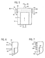
- the upper portion of the bellows will now break both the lower and upper beams of light passing through housing 78 from lower and upper light sources 96 and 98 to light sensors 100 and 102, respectively. See Fig. 4.
- the interruption of both the upper and lower light beams will be detected by light sensors 100 and 102, and the corresponding output state of both the sensors in conductors 104 and 106 comprises an indication that the volume of gases in anaesthesia circuit 37 has increased.
- the output states of upper and lower light sensors 100 and 102 provide a simple, reliable, and straightforward indication of whether the gas volume in anaesthesia circuit 37 operating in the closed circuit mode is at the desired level, has increased, or has decreased.
- Fig. 6 schematically shows an electrical detector in the form of a capacitive detector means and Fig. 7 shows a magnetic detector in the form of magnet 116 mounted on the upper portion of bellows 74 and magnetically operable reed switches 118, 120 mounted on housing 78.
- Fig. 7 shows a magnetic detector in the form of magnet 116 mounted on the upper portion of bellows 74 and magnetically operable reed switches 118, 120 mounted on housing 78.
- other types of detectors such as mechanical switches, may be employed.
- Fig. 2 shows the light sources and light sensors mounted on opposite sides of bellows 74
- the light sources and light sensors may be mounted on the same side of bellows 74 and a light reflecting mirror positioned beyond the other side of bellows 74.
- the mirror can be mounted on the upper portion of bellows 74 in the same manner as the electrical or magnetic arrangements shown in Figs. 6 and 7.
- a light source could be mounted on bellows 74 for use with appropriate sensors on housing 78.
- the sensor elements of device 90 may be connected to control 108 that, in turn, is connected to the gas flow controlling valves 22 and 24 of anaesthesia machine 12.
- Control 108 is also connected, via conductor 110, to oxygen sensor 46 connected in inspiration limb 38 of anaesthesia circuit 37.
- Oxygen sensor 46 measures the inspired oxygen concentration (FiO 2 ) in anaesthesia circuit 37.
- Control 108 may carry out automatic control of the volume and composition of respiratory gas in anaesthesia circuit 37 by appropriate operation of valves 22 and 24 in accordance with the inputs received from conductors 104, 106, and 110. This operation may be carried out in accordance with the following logic table which shows circuit conditions and operation as FiO 2 varies with respect to a desired level as set by an anesthesiologist or other operator.
- anaesthesia apparatus has been described as having detectors 92 and 94 connected to control 108 for automatic operation, it will be appreciated that the detector may operate visual or audio indicators to permit manual control of the respiratory gas volume in the anaesthesia circuit by an anesthesiologist, or other medical personnel.
- anaesthesia apparatus has been described as employing oxygen and nitrous oxide, it will also be appreciated that a supply of air may be used in addition to, or in lieu of, the nitrous oxide. Or, the apparatus may be operated solely with oxygen.
Landscapes
- Health & Medical Sciences (AREA)
- Emergency Medicine (AREA)
- Pulmonology (AREA)
- Engineering & Computer Science (AREA)
- Anesthesiology (AREA)
- Biomedical Technology (AREA)
- Heart & Thoracic Surgery (AREA)
- Hematology (AREA)
- Life Sciences & Earth Sciences (AREA)
- Animal Behavior & Ethology (AREA)
- General Health & Medical Sciences (AREA)
- Public Health (AREA)
- Veterinary Medicine (AREA)
- Measurement Of The Respiration, Hearing Ability, Form, And Blood Characteristics Of Living Organisms (AREA)
- Respiratory Apparatuses And Protective Means (AREA)
Claims (16)
- Narkoseapparat, der einen Narkosekreis (38 - 66) und eine Vorrichtung (90) für das Bestimmen von Gasvolumen und Volumenänderungen im Narkosekreis (38 - 66) umfasst, wobei der Kreis ein Beatmungsgerät, das einen Balgaufbau aufweist, einschließt, wobei der Balgaufbau umfasst:wobei die ersten und zweiten Sensoren (92, 94) in Bezug auf den Balg (74) so angeordnet sind, dass die ersten und zweiten Sensoren Anzeigen für das Vorhandensein des Balges liefern, wenn sich der Balg in der expandierten Position jenseits der vorgegebenen expandierten Position befindet;ein Gehäuse (78);einen Balg (74), der im Gehäuse angeordnet und sich in Fluidverbindung mit dem Narkosekreis befindet, wobei beim Gebrauch der Balg (74) in diesem Gehäuse komprimiert wird, um Gas in den Kreis zu einem Patienten während des Einatmens zu liefern, und in diesem Gehäuse (78) expandiert wird, um Gas vom Patienten während des Ausatmens zu empfangen, wobei der Balg wiederholt eine expandierte Position in diesem Gehäuse annimmt, die das Volumen des Gases im Narkosekreis anzeigt, wobei der Balg in diesem Gehäuse entlang eines Bewegungsweges in einer ersten Richtung weg von der expandierten Position bei einer Kompression bewegbar ist und zur expandierten Position durch eine Bewegung in diesem Gehäuse entlang des Bewegungspfads in einer zweiten Richtung entgegengesetzt zur ersten Richtung bei einer Expansion zurückkehrt;einen Beatmungsgerätantrieb (84), der mit dem Gehäuse (78) verbunden ist, um Antriebsgas an das Gehäuse zu liefern, um den Balg (74) zu komprimieren;und die Bestimmungsvorrichtung (90) folgendes umfasst:einen ersten Sensor (92), der in bezug auf den Balg für das Detektieren und das Liefern einer Anzeige angeordnet ist, wenn sich der Balg in einer vorgegebenen expandierten Position befindet, wobei die vorgegebene Position einem vorgegebenen Volumen von Gas im Narkosekreis entspricht; undeinen zweiten Sensor (94), der in Bezug auf den Balg (74) für das Detektieren und das Liefern einer Anzeige angeordnet ist, wenn sich der Balg in einer expandierten Position befindet, die jenseits der vorgegebenen expandierten Position in der zweiten Richtung der Bewegung entlang des Bewegungspfads des Balges liegt,
wodurch eine Anzeige vom ersten Sensor (92) beim Fehlen einer Anzeige vom zweiten Sensor (94) anzeigt, dass das vorgegebenen Volumen des Gases im Narkosekreis vorhanden ist, und wiederholte Anzeigen des ersten Sensor beim Fehlen von Anzeigen des zweiten Sensors anzeigen, dass das Volumen des Gases im Narkosekreis sich im allgemeinen nicht ändert, Anzeigen sowohl vom ersten Sensor als auch vom zweiten Sensor anzeigen, dass das Volumen des Gases im Narkosekreis größer als das vorgegebene Volumen ist, und das Fehlen von Anzeigen sowohl vom ersten Sensor als auch vom zweiten Sensor anzeigt, dass das Volumen des Gases im Narkosekreis geringer als das vorgegebene Volumen ist. - Apparat nach Anspruch 1, wobei die ersten und zweiten Sensoren einstellbar entlang des Bewegungswegs des Balges angeordnet sind.
- Apparat nach Anspruch 1 oder 2, weiter definiert als einer für das Aufrechthalten des Volumens des Gases in einem geschlossenen Narkosekreis, wobei der Apparat weiter eine Steuervorrichtung (108) einschließt, die mit den ersten und zweiten Sensoren verbunden ist, wobei die Steuervorrichtung mit Gaszuführvorrichtungen (14, 16) für den Narkosekreis verbunden ist, wobei die Steuervorrichtung auf die Anzeigen der Sensoren anspricht, um die Gaszuführvorrichtungen zu betätigen, um das Volumen des Gases im geschlossenen Narkosekreis aufrecht zu halten.
- Apparat nach Anspruch 3, wobei die Gaszufühworrichtungen folgendes einschließen:eine Quelle mit Sauerstoffgas (14), wobei der Kreis weiter Vorrichtungen (46) für das Messen und das Anzeigen einer Sauerstoffkonzentration im Narkosekreis einschließt, und wobei die Steuervorrichtung (108) mit den Vorrichtungen für das Messen und Anzeigen der Sauerstoffkonzentration verbindbar ist und auf diese Vorrichtungen anspricht, um die Gaszuführvorrichtungen zu betätigen.
- Apparat nach einem der vorhergehenden Ansprüche, weiter definiert als einer für das Liefern eines Narkosemittels an das Individuum, und wobei die Gasversorgungsvorrichtung eine Quelle mit einem Narkosemittel (34) einschließt.
- Apparat nach einem der vorhergehenden Ansprüche, wobei die ersten und zweiten Sensoren entlang einer Richtung, die im wesentlichen parallel zum Bewegungsweg des Balges verläuft, inkrementell voneinander entfernt werden.
- Apparat nach einem der vorhergehenden Ansprüche, wobei die ersten und zweiten Sensoren inkrementell voneinander um eine Größe beabstandet werden, die gemäß der gewünschten Genauigkeit und Stabilität der Vorrichtung ausgewählt wird.
- Apparat nach einem der vorhergehenden Ansprüche, wobei der Balg in dem Gehäuse angeordnet ist, um sich nach oben bei der Expansion zu bewegen und um sich nach unten bei der Kompression zu bewegen, und wobei die ersten und zweiten Sensoren in Bezug aufeinander so ausgerichtet sind, dass der erste Sensor (92) einen unteren Sensor umfasst, und dass der zweite Sensor (94) einen oberen Sensor umfasst, der oberhalb des ersten unteren Sensors in der zweiten Bewegungsrichtung entlang des Bewegungsweges des Balgs angeordnet ist.
- Apparat nach einem der vorhergehenden Ansprüche, wobei mindestens einer der Sensoren einen mit Licht betriebenen Sensor (96, 98, 100, 102) umfasst.
- Apparat nach Anspruch 9, wobei der mindestens eine Sensor eine Lichtquelle (96, 98), die einen Lichtstrahl aussendet, und einen Lichtdetektor (100, 102) für das Empfangen des Lichts umfasst, wobei die Position des Balgs bestimmt, ob der Lichtstrahl vom Lichtdetektor empfangen wird.
- Apparat nach Anspruch 9, wobei der mindestens eine Sensor eine Lichtquelle (96, 98), die einen Lichtstrahl aussendet, und einen Lichtdetektor (100, 102) für das Empfangen des Lichts umfasst, wobei der Lichtstrahl durch den Balg durch eine Bewegung entlang des Bewegungswegs unterbrochen wird.
- Apparat nach Anspruch 10, wobei der mindestens eine Sensor einen Spiegel für das Reflektieren des Lichtstrahls einschließt.
- Apparat nach einem der Ansprüche 1 bis 9, wobei mindestens einer der Sensoren magnetisch betätigte Sensorvorrichtungen (116, 118, 120) umfasst.
- Apparat nach einem der Ansprüche 1 bis 9, wobei mindestens einer der Sensoren elektrisch betätigte Sensorvorrichtungen umfasst.
- Apparat nach Anspruch 14, wobei mindestens einer der Sensoren kapazitiv betätigte Sensorvorrichtungen (113, 115) umfasst.
- Apparat nach einem der Ansprüche 1 bis 9, wobei mindestens einer der Sensoren mechanisch betätigte Sensarvorrichtungen umfasst.
Applications Claiming Priority (3)
| Application Number | Priority Date | Filing Date | Title |
|---|---|---|---|
| US916062 | 1997-08-21 | ||
| US08/916,062 US6213120B1 (en) | 1997-08-21 | 1997-08-21 | Device and method for determining gas volume and volumetric changes in a ventilator |
| PCT/IB1998/001251 WO1999010034A1 (en) | 1997-08-21 | 1998-08-14 | Device and method for determining gas volume and volumetric changes in an anaesthesia system |
Publications (2)
| Publication Number | Publication Date |
|---|---|
| EP0942764A1 EP0942764A1 (de) | 1999-09-22 |
| EP0942764B1 true EP0942764B1 (de) | 2005-10-19 |
Family
ID=25436646
Family Applications (1)
| Application Number | Title | Priority Date | Filing Date |
|---|---|---|---|
| EP98936605A Expired - Lifetime EP0942764B1 (de) | 1997-08-21 | 1998-08-14 | Vorrichtung zur bestimmung des gasvolumens sowie volumenänderungen in einem narkosesystem |
Country Status (5)
| Country | Link |
|---|---|
| US (1) | US6213120B1 (de) |
| EP (1) | EP0942764B1 (de) |
| JP (1) | JP2001504745A (de) |
| DE (1) | DE69831931T2 (de) |
| WO (1) | WO1999010034A1 (de) |
Families Citing this family (81)
| Publication number | Priority date | Publication date | Assignee | Title |
|---|---|---|---|---|
| US5878745A (en) | 1996-03-01 | 1999-03-09 | Brain; Archibald I.J. | Gastro-laryngeal mask |
| US5857458A (en) * | 1997-09-26 | 1999-01-12 | Ohmeda Inc. | Automatic bellows refill |
| US7331346B2 (en) * | 1997-12-24 | 2008-02-19 | Indian Ocean Medical, Inc. | Monitoring and control for a laryngeal mask airway device |
| GB9727367D0 (en) * | 1997-12-24 | 1998-02-25 | Brain Archibald Ian Jeremy | Improvements in laryngeal mask airway devices |
| US6319724B1 (en) * | 1998-06-19 | 2001-11-20 | Cyrano Sciences, Inc. | Trace level detection of analytes using artificial olfactometry |
| GB9821771D0 (en) * | 1998-10-06 | 1998-12-02 | Brain Archibald Ian Jeremy | Improvements relating to laryngeal mask airway devices |
| EP1171182B1 (de) * | 1999-04-07 | 2008-11-19 | eVent Medical Limited | Beatmungsgerät |
| SE9901510D0 (sv) * | 1999-04-27 | 1999-04-27 | Siemens Elema Ab | Breathing gas supply apparatus |
| US6378520B1 (en) * | 1999-10-29 | 2002-04-30 | Salter Labs | Variable pressure and flow control for a pneumatically-operated gas demand apparatus |
| JP4084523B2 (ja) * | 2000-03-10 | 2008-04-30 | 大陽日酸株式会社 | キセノンを使用した麻酔装置 |
| FR2811577B1 (fr) * | 2000-07-11 | 2003-05-23 | Taema | Installation de ventilation en gaz d'un patient |
| US7055520B2 (en) * | 2001-01-17 | 2006-06-06 | David Swisa | Device and method for detecting the flow of a gas |
| KR100422256B1 (ko) * | 2001-12-26 | 2004-03-11 | 주식회사 멕 | 압력 조절 방식의 인공 호흡 장치 |
| GB0210022D0 (en) * | 2002-05-01 | 2002-06-12 | Air Prod & Chem | Gas dispenser and recovery apparatus |
| US6874501B1 (en) | 2002-12-06 | 2005-04-05 | Robert H. Estetter | Lung simulator |
| DE10360229B3 (de) * | 2003-12-20 | 2004-12-09 | Dräger Medical AG & Co. KGaA | Vorrichtung und Verfahren zur Dosierung von Atemgas |
| WO2006050384A2 (en) * | 2004-11-01 | 2006-05-11 | Salter Labs | System and method for conserving oxygen delivery while maintaining saturation |
| GB0510951D0 (en) * | 2005-05-27 | 2005-07-06 | Laryngeal Mask Company The Ltd | Laryngeal mask airway device |
| EP1893992B1 (de) * | 2005-06-17 | 2011-09-21 | Maquet Critical Care AB | Bereitstellung einer Gasmesskammer für Ultraschallmessungen mit verringertem Temperatureinfluss |
| DE102005032977B3 (de) * | 2005-07-14 | 2006-12-21 | Schmidt, Klaus, Prof. Dr. | Vorrichtung und Verfahren zur Aufbereitung von Gasgemischen |
| US7832398B2 (en) | 2005-12-29 | 2010-11-16 | General Elecrtic Company | Arrangement in connection with an anaesthesia/ventilation system for a patient and a gas separation unit for an anaesthesia/ventilation system |
| US20070274845A1 (en) * | 2006-05-25 | 2007-11-29 | Air Products And Chemicals, Inc. | Fluid Storage And Dispensing System |
| US8127762B2 (en) * | 2006-06-29 | 2012-03-06 | Maquet Critical Care Ab | Anaesthesia apparatus and method for operating an anaesthesia apparatus |
| US20080029173A1 (en) * | 2006-08-07 | 2008-02-07 | Diperna Paul Mario | Variable flow reshapable flow restrictor apparatus and related methods |
| US20080035148A1 (en) * | 2006-08-09 | 2008-02-14 | Fuhrman Bradley P | Device And Method Of Isolating Bias Flow Using Partition Position |
| AU2007314070B2 (en) * | 2006-11-01 | 2014-06-05 | Cliff Ansel | Portable life support apparatus |
| DE102007019487B3 (de) * | 2007-04-25 | 2008-04-10 | Dräger Medical AG & Co. KG | Modulares Beatmungssystem für die maschinelle Beatmung eines Patienten |
| US20080276940A1 (en) * | 2007-05-08 | 2008-11-13 | Fuhrman Bradley P | Breathing-Gas Delivery System With Exhaust Gas Filter Body And Method Of Operating A Breathing-Gas Delivery System |
| EP2008679A1 (de) | 2007-06-28 | 2008-12-31 | General Electric Company | Patientenbeatmungssystem |
| EP2185228A4 (de) * | 2007-08-22 | 2014-07-30 | Univ New York State Res Found | Atemgas-abgabe- und sharing-system und verfahren |
| US20090191067A1 (en) * | 2008-01-25 | 2009-07-30 | Phluid,Inc. | Two chamber pumps and related methods |
| US8986253B2 (en) | 2008-01-25 | 2015-03-24 | Tandem Diabetes Care, Inc. | Two chamber pumps and related methods |
| US8056582B2 (en) * | 2008-08-08 | 2011-11-15 | Tandem Diabetes Care, Inc. | System of stepped flow rate regulation using compressible members |
| EP2334234A4 (de) | 2008-09-19 | 2013-03-20 | Tandem Diabetes Care Inc | Vorrichtung zur messung der konzentration eines gelösten stoffs und entsprechende verfahren |
| US8707954B2 (en) * | 2008-10-09 | 2014-04-29 | Daniel A. McCarthy | Air/oxygen supply system and method |
| US20100175695A1 (en) * | 2009-01-12 | 2010-07-15 | Mindray Ds Usa, Inc. | Auxiliary gas mixing in an anesthesia system |
| US8267081B2 (en) * | 2009-02-20 | 2012-09-18 | Baxter International Inc. | Inhaled anesthetic agent therapy and delivery system |
| US9250106B2 (en) | 2009-02-27 | 2016-02-02 | Tandem Diabetes Care, Inc. | Methods and devices for determination of flow reservoir volume |
| US8573027B2 (en) | 2009-02-27 | 2013-11-05 | Tandem Diabetes Care, Inc. | Methods and devices for determination of flow reservoir volume |
| GB0903654D0 (en) | 2009-03-03 | 2009-04-15 | Laryngeal Mask Company The Ltd | Artificial airway device |
| EP3434307B1 (de) | 2009-07-06 | 2020-05-20 | Teleflex Life Sciences Unlimited Company | Künstlicher atemweg |
| US8758323B2 (en) | 2009-07-30 | 2014-06-24 | Tandem Diabetes Care, Inc. | Infusion pump system with disposable cartridge having pressure venting and pressure feedback |
| CN102498377B (zh) | 2009-08-13 | 2014-05-14 | 奇姆德恩医疗有限公司 | 压力指示器 |
| JP5360897B2 (ja) * | 2009-08-28 | 2013-12-04 | 泉工医科工業株式会社 | 麻酔システムおよび麻酔システムの運転方法 |
| US8844521B2 (en) | 2010-04-09 | 2014-09-30 | Daniel A. McCarthy | Air/oxygen ventilator system and method |
| GB201016562D0 (en) | 2010-10-01 | 2010-11-17 | Laryngeal Mask Company The Ltd | Artificial airway device |
| WO2012049448A2 (en) | 2010-10-15 | 2012-04-19 | The Laryngeal Mask Company Limited | Artificial airway device |
| WO2012083276A2 (en) * | 2010-12-17 | 2012-06-21 | Spacelabs Healthcare, Llc | Dynamic graphic respiratory communication system |
| CN103429291A (zh) | 2011-02-02 | 2013-12-04 | 梅田有限公司 | 改进的人工气道 |
| US20130068222A1 (en) * | 2011-06-20 | 2013-03-21 | Klaus Michael SCHMIDT | Anesthetic circuit and a method for using the anesthetic circuit |
| DE102012010525A1 (de) * | 2011-07-02 | 2013-01-03 | Dräger Medical GmbH | Verfahren zur Funktionskontrolle eines Beatmungssystems |
| US20130019867A1 (en) * | 2011-07-20 | 2013-01-24 | General Electric Company | Anesthesia machine and system |
| GB201120628D0 (en) | 2011-11-30 | 2012-01-11 | Laryngeal Mask Company The Ltd | Endoscopy device |
| US9993604B2 (en) | 2012-04-27 | 2018-06-12 | Covidien Lp | Methods and systems for an optimized proportional assist ventilation |
| US9199050B2 (en) * | 2012-04-30 | 2015-12-01 | Carefusion Corporation | Arrangement and method for guiding expired respiratory gas flow using gas routing device |
| US9180242B2 (en) | 2012-05-17 | 2015-11-10 | Tandem Diabetes Care, Inc. | Methods and devices for multiple fluid transfer |
| US9555186B2 (en) | 2012-06-05 | 2017-01-31 | Tandem Diabetes Care, Inc. | Infusion pump system with disposable cartridge having pressure venting and pressure feedback |
| US10362967B2 (en) | 2012-07-09 | 2019-07-30 | Covidien Lp | Systems and methods for missed breath detection and indication |
| US9027552B2 (en) | 2012-07-31 | 2015-05-12 | Covidien Lp | Ventilator-initiated prompt or setting regarding detection of asynchrony during ventilation |
| CN104619370B9 (zh) * | 2012-09-12 | 2018-05-25 | 马奎特紧急护理公司 | 用于主动控制递送至患者的氧气的麻醉系统 |
| US10076620B2 (en) | 2012-12-22 | 2018-09-18 | Dmf Medical Incorporated | Anesthetic circuit having a hollow fiber membrane |
| US9173998B2 (en) | 2013-03-14 | 2015-11-03 | Tandem Diabetes Care, Inc. | System and method for detecting occlusions in an infusion pump |
| US9180243B2 (en) | 2013-03-15 | 2015-11-10 | Tandem Diabetes Care, Inc. | Detection of infusion pump conditions |
| NL1040531C2 (nl) * | 2013-12-06 | 2015-06-09 | Alcmair Partners B V | Inrichting voor het beademen van patiã«nten. |
| US9950129B2 (en) | 2014-10-27 | 2018-04-24 | Covidien Lp | Ventilation triggering using change-point detection |
| US11471636B2 (en) | 2015-04-15 | 2022-10-18 | Medline Industries, Lp | Moisture removal and condensation and humidity management apparatus for a breathing circuit |
| US10556074B2 (en) | 2015-07-17 | 2020-02-11 | Daniel A. McCarthy | Artificial respiration system with timing control and automatic mask detection |
| CN105233383A (zh) * | 2015-09-12 | 2016-01-13 | 张萍 | 一种具有自动报警装置的可折叠麻醉机 |
| US10478586B2 (en) | 2016-03-02 | 2019-11-19 | Daniel A. McCarthy | Artificial respiration system and method having automatic mask detection |
| WO2017178825A1 (en) * | 2016-04-15 | 2017-10-19 | Christopher Charles Farrell | An apparatus and a method for determining a measurement error of a displacement volumetric meter, a meter monitoring device, and a meter measurement error determining device |
| EP3528880B1 (de) | 2016-10-19 | 2021-07-07 | Teleflex Medical Incorporated | Feuchtigkeitsentnahme- sowie kondensations- und feuchtigkeitsmanagementvorrichtung für einen atemkreis |
| EP4173664A3 (de) | 2017-07-10 | 2023-05-31 | Medline Industries, LP | Feuchtigkeitsentfernungs- und kondensations- und feuchtigkeitsverwaltungsvorrichtung für einen atemkreislauf |
| US11338158B2 (en) * | 2018-03-15 | 2022-05-24 | Safran Aerotechnics Sas | System and a method for delivering breathing gas to passengers on-board an aircraft |
| EP3823708B1 (de) * | 2018-07-19 | 2024-10-09 | Aviation Works Limited | Belüftungsvorrichtung und maske |
| US11324954B2 (en) | 2019-06-28 | 2022-05-10 | Covidien Lp | Achieving smooth breathing by modified bilateral phrenic nerve pacing |
| WO2021221518A1 (en) * | 2020-05-01 | 2021-11-04 | Fisher & Paykel Healthcare Limited | A respiratory support apparatus |
| US11369763B2 (en) * | 2020-07-31 | 2022-06-28 | Soco International Llc | Respiratory ventilatory device and method of operating same |
| US12138393B2 (en) * | 2021-02-04 | 2024-11-12 | GE Precision Healthcare LLC | Ventilator systems and methods |
| FR3120314B1 (fr) * | 2021-03-04 | 2024-07-26 | Lair Liquide Sa Pour L’Etude Et Lexploitation Des Procedes Georges Claude | Interface de ventilation de patient destinée à être couplée à un ventilateur médical et à une source de gaz |
| CN117531075A (zh) * | 2022-12-30 | 2024-02-09 | 深圳迈瑞动物医疗科技股份有限公司 | 通气设备及风箱装置的通气控制方法 |
| CN117442839A (zh) * | 2023-11-23 | 2024-01-26 | 中船重工(重庆)西南装备研究院有限公司 | 一种便携式可二次开发的呼吸模块 |
Family Cites Families (17)
| Publication number | Priority date | Publication date | Assignee | Title |
|---|---|---|---|---|
| US4127121A (en) | 1976-09-17 | 1978-11-28 | University Of Utah | Oxygen and anesthesia delivery and monitoring device |
| JPS5538193A (en) * | 1978-08-24 | 1980-03-17 | Grant Graham Cameron | Ventilator for medical appliance |
| US4340044A (en) * | 1980-03-20 | 1982-07-20 | Berkshire Research Partners | Volume ventilator |
| US4354984A (en) | 1981-08-03 | 1982-10-19 | Baxter Travenol Laboratories, Inc. | Liquid level controller for a humidifier |
| US4432238A (en) * | 1982-07-22 | 1984-02-21 | Tward 2001 Limited | Capacitive pressure transducer |
| US4493614A (en) | 1982-10-08 | 1985-01-15 | Lifecare Services, Inc. | Pump for a portable ventilator |
| DE3712598A1 (de) * | 1987-04-14 | 1988-10-27 | Siemens Ag | Inhalations-anaesthesiegeraet |
| FR2647576A1 (fr) | 1989-05-29 | 1990-11-30 | Revo Air Ste Civile Etu Rech | Detecteur de respiration et d'arret respiratoire |
| US5277175A (en) | 1991-07-12 | 1994-01-11 | Riggs John H | Continuous flow nebulizer apparatus and method, having means maintaining a constant-level reservoir |
| FI92286C (fi) * | 1992-02-21 | 1994-10-25 | Instrumentarium Oy | Laitteisto potilaalle hengitysjakson aikana toimitetun kaasutilavuuden säätämiseksi |
| DE4207533C2 (de) * | 1992-03-10 | 1994-03-31 | Draegerwerk Ag | Atemschutzgerät mit Atemluftrückführung |
| US5317918A (en) * | 1992-05-18 | 1994-06-07 | Lew Hyok S | High resolution pressure sensor |
| SE9400992L (sv) * | 1994-03-24 | 1995-05-02 | Siemens Elema Ab | Andningsgassystem med en trycköverförande bäljanordning mellan andningskretsen och drivgasapparaten |
| FI95442C (fi) | 1994-06-21 | 1996-02-12 | Instrumentarium Oy | Sovitelma ventilaattorin yhteydessä |
| SE9402537L (sv) | 1994-07-20 | 1996-01-21 | Siemens Elema Ab | Narkossystem |
| GB9511651D0 (en) * | 1995-06-08 | 1995-08-02 | Univ Wales Medicine | Blood Volume Measurement |
| US5857458A (en) * | 1997-09-26 | 1999-01-12 | Ohmeda Inc. | Automatic bellows refill |
-
1997
- 1997-08-21 US US08/916,062 patent/US6213120B1/en not_active Expired - Fee Related
-
1998
- 1998-08-14 EP EP98936605A patent/EP0942764B1/de not_active Expired - Lifetime
- 1998-08-14 WO PCT/IB1998/001251 patent/WO1999010034A1/en not_active Ceased
- 1998-08-14 JP JP51411099A patent/JP2001504745A/ja active Pending
- 1998-08-14 DE DE69831931T patent/DE69831931T2/de not_active Expired - Fee Related
Also Published As
| Publication number | Publication date |
|---|---|
| EP0942764A1 (de) | 1999-09-22 |
| JP2001504745A (ja) | 2001-04-10 |
| US6213120B1 (en) | 2001-04-10 |
| DE69831931T2 (de) | 2006-05-11 |
| DE69831931D1 (de) | 2005-11-24 |
| WO1999010034A1 (en) | 1999-03-04 |
Similar Documents
| Publication | Publication Date | Title |
|---|---|---|
| US6213120B1 (en) | Device and method for determining gas volume and volumetric changes in a ventilator | |
| US7836882B1 (en) | Electronic anesthesia delivery apparatus | |
| US5857458A (en) | Automatic bellows refill | |
| EP0916358B1 (de) | Not-Meldegerät für einen Durchflussmesser | |
| US20210146078A1 (en) | Anesthesia machine and system | |
| US5918597A (en) | Peep control in a piston ventilator | |
| EP0659445B1 (de) | Stickoxid-Zuführungssystem | |
| US11904098B2 (en) | Additive gas delivery apparatus with backup | |
| EP0621049B1 (de) | Verfahren und Geräte für Frischgasabgabe bei manueller Ventilation | |
| US8141552B2 (en) | Respiratory anaesthesia apparatus with device for measuring the xenon concentration | |
| EP0982044B1 (de) | Vorrichtung zur Ermittlung von leeren Gasbehältern in einen Beatmungsgerät | |
| US3910270A (en) | Portable volume cycle respirator | |
| CA1103118A (en) | Combination anesthesia and intensive care apparatus | |
| US20160354568A1 (en) | System and method for ventilating lungs | |
| EP3479862A1 (de) | Verfahren für inhalationswirkung auf den körper und vorrichtung zur durchführung des verfahrens | |
| JPH0417065B2 (de) | ||
| US6125848A (en) | Distal volume monitoring | |
| JPS6113972A (ja) | ガス調合部分と、普通機械的に動かされる換気機部分を含む麻酔および/または人工呼吸装置 | |
| CN111093746A (zh) | 麻醉机、氧电池校准系统及其校准方法 | |
| Manohar et al. | The Anesthesia Machine | |
| Sykes et al. | A new microprocessor-controlled anaesthetic machine | |
| CN120919476A (zh) | 一种麻醉机 | |
| van der Walt et al. | Principles of the anaesthetic machine | |
| Crosby et al. | The anaesthetic machine | |
| EP3698834A1 (de) | Medizinische gaszufuhrvorrichtung mit einem schnell reagierenden sauerstoffsensor |
Legal Events
| Date | Code | Title | Description |
|---|---|---|---|
| PUAI | Public reference made under article 153(3) epc to a published international application that has entered the european phase |
Free format text: ORIGINAL CODE: 0009012 |
|
| 17P | Request for examination filed |
Effective date: 19990519 |
|
| AK | Designated contracting states |
Kind code of ref document: A1 Designated state(s): DE FR GB NL SE |
|
| RAP1 | Party data changed (applicant data changed or rights of an application transferred) |
Owner name: INSTRUMENTARIUM CORPORATION |
|
| RIN1 | Information on inventor provided before grant (corrected) |
Inventor name: JAERNEFELT, GUSTAF Inventor name: BLOCK, FRANK, E., JR. |
|
| 17Q | First examination report despatched |
Effective date: 20021211 |
|
| GRAP | Despatch of communication of intention to grant a patent |
Free format text: ORIGINAL CODE: EPIDOSNIGR1 |
|
| RTI1 | Title (correction) |
Free format text: DEVICE FOR DETERMINING GAS VOLUME AND VOLUMETRIC CHANGES IN AN ANAESTHESIA SYSTEM |
|
| GRAS | Grant fee paid |
Free format text: ORIGINAL CODE: EPIDOSNIGR3 |
|
| GRAA | (expected) grant |
Free format text: ORIGINAL CODE: 0009210 |
|
| AK | Designated contracting states |
Kind code of ref document: B1 Designated state(s): DE FR GB NL SE |
|
| PG25 | Lapsed in a contracting state [announced via postgrant information from national office to epo] |
Ref country code: NL Free format text: LAPSE BECAUSE OF FAILURE TO SUBMIT A TRANSLATION OF THE DESCRIPTION OR TO PAY THE FEE WITHIN THE PRESCRIBED TIME-LIMIT Effective date: 20051019 |
|
| REG | Reference to a national code |
Ref country code: GB Ref legal event code: FG4D |
|
| REF | Corresponds to: |
Ref document number: 69831931 Country of ref document: DE Date of ref document: 20051124 Kind code of ref document: P |
|
| PG25 | Lapsed in a contracting state [announced via postgrant information from national office to epo] |
Ref country code: SE Free format text: LAPSE BECAUSE OF FAILURE TO SUBMIT A TRANSLATION OF THE DESCRIPTION OR TO PAY THE FEE WITHIN THE PRESCRIBED TIME-LIMIT Effective date: 20060119 |
|
| NLV1 | Nl: lapsed or annulled due to failure to fulfill the requirements of art. 29p and 29m of the patents act | ||
| PLBE | No opposition filed within time limit |
Free format text: ORIGINAL CODE: 0009261 |
|
| STAA | Information on the status of an ep patent application or granted ep patent |
Free format text: STATUS: NO OPPOSITION FILED WITHIN TIME LIMIT |
|
| 26N | No opposition filed |
Effective date: 20060720 |
|
| EN | Fr: translation not filed | ||
| PG25 | Lapsed in a contracting state [announced via postgrant information from national office to epo] |
Ref country code: FR Free format text: LAPSE BECAUSE OF FAILURE TO SUBMIT A TRANSLATION OF THE DESCRIPTION OR TO PAY THE FEE WITHIN THE PRESCRIBED TIME-LIMIT Effective date: 20061208 |
|
| PGFP | Annual fee paid to national office [announced via postgrant information from national office to epo] |
Ref country code: GB Payment date: 20070830 Year of fee payment: 10 |
|
| PGFP | Annual fee paid to national office [announced via postgrant information from national office to epo] |
Ref country code: DE Payment date: 20071001 Year of fee payment: 10 |
|
| PG25 | Lapsed in a contracting state [announced via postgrant information from national office to epo] |
Ref country code: FR Free format text: LAPSE BECAUSE OF FAILURE TO SUBMIT A TRANSLATION OF THE DESCRIPTION OR TO PAY THE FEE WITHIN THE PRESCRIBED TIME-LIMIT Effective date: 20051019 |
|
| GBPC | Gb: european patent ceased through non-payment of renewal fee |
Effective date: 20080814 |
|
| PG25 | Lapsed in a contracting state [announced via postgrant information from national office to epo] |
Ref country code: DE Free format text: LAPSE BECAUSE OF NON-PAYMENT OF DUE FEES Effective date: 20090303 |
|
| PG25 | Lapsed in a contracting state [announced via postgrant information from national office to epo] |
Ref country code: GB Free format text: LAPSE BECAUSE OF NON-PAYMENT OF DUE FEES Effective date: 20080814 |