EP0942802B1 - Machine-outil a commande manuelle - Google Patents
Machine-outil a commande manuelle Download PDFInfo
- Publication number
- EP0942802B1 EP0942802B1 EP97926899A EP97926899A EP0942802B1 EP 0942802 B1 EP0942802 B1 EP 0942802B1 EP 97926899 A EP97926899 A EP 97926899A EP 97926899 A EP97926899 A EP 97926899A EP 0942802 B1 EP0942802 B1 EP 0942802B1
- Authority
- EP
- European Patent Office
- Prior art keywords
- groove
- ring
- clamping
- power tool
- spindle
- Prior art date
- Legal status (The legal status is an assumption and is not a legal conclusion. Google has not performed a legal analysis and makes no representation as to the accuracy of the status listed.)
- Expired - Lifetime
Links
Images



Classifications
-
- B—PERFORMING OPERATIONS; TRANSPORTING
- B25—HAND TOOLS; PORTABLE POWER-DRIVEN TOOLS; MANIPULATORS
- B25F—COMBINATION OR MULTI-PURPOSE TOOLS NOT OTHERWISE PROVIDED FOR; DETAILS OR COMPONENTS OF PORTABLE POWER-DRIVEN TOOLS NOT PARTICULARLY RELATED TO THE OPERATIONS PERFORMED AND NOT OTHERWISE PROVIDED FOR
- B25F5/00—Details or components of portable power-driven tools not particularly related to the operations performed and not otherwise provided for
- B25F5/001—Gearings, speed selectors, clutches or the like specially adapted for rotary tools
-
- B—PERFORMING OPERATIONS; TRANSPORTING
- B24—GRINDING; POLISHING
- B24B—MACHINES, DEVICES, OR PROCESSES FOR GRINDING OR POLISHING; DRESSING OR CONDITIONING OF ABRADING SURFACES; FEEDING OF GRINDING, POLISHING, OR LAPPING AGENTS
- B24B23/00—Portable grinding machines, e.g. hand-guided; Accessories therefor
- B24B23/02—Portable grinding machines, e.g. hand-guided; Accessories therefor with rotating grinding tools; Accessories therefor
-
- B—PERFORMING OPERATIONS; TRANSPORTING
- B24—GRINDING; POLISHING
- B24B—MACHINES, DEVICES, OR PROCESSES FOR GRINDING OR POLISHING; DRESSING OR CONDITIONING OF ABRADING SURFACES; FEEDING OF GRINDING, POLISHING, OR LAPPING AGENTS
- B24B23/00—Portable grinding machines, e.g. hand-guided; Accessories therefor
- B24B23/02—Portable grinding machines, e.g. hand-guided; Accessories therefor with rotating grinding tools; Accessories therefor
- B24B23/022—Spindle-locking devices, e.g. for mounting or removing the tool
-
- B—PERFORMING OPERATIONS; TRANSPORTING
- B24—GRINDING; POLISHING
- B24B—MACHINES, DEVICES, OR PROCESSES FOR GRINDING OR POLISHING; DRESSING OR CONDITIONING OF ABRADING SURFACES; FEEDING OF GRINDING, POLISHING, OR LAPPING AGENTS
- B24B45/00—Means for securing grinding wheels on rotary arbors
- B24B45/006—Quick mount and release means for disc-like wheels, e.g. on power tools
Definitions
- the invention relates to a hand machine tool, for. B. Angle grinder, hand-held circular saw or the like in accordance with the genus of claim 1.
- an SDS click nut which for hand machine tools with disk-shaped tools is usable, being on the free end of the outside disc-shaped tool-carrying work spindle can be clamped and for tool change with a short turning stroke is adjustable by hand in the release direction, the Clamping pressure on the disc-shaped tool releases and the SDS-Click nut can be easily unscrewed by hand.
- DE-A-44 32 973 is a generic one Hand tool known, the spindle lock over a pivot pin that can be actuated by a hand lever can be activated, wherein a locking cam arranged on the pivot pin has a semicircular shape Has cross-section.
- the locking cam is for Entry into opposite, semicircular grooves of the Groove ring of a clamping flange provided.
- this semicircular Grooves the detent cam swings out Operating position of the hand lever by turning it on.
- This known spindle lock is easy to manufacture and works reliably, but is in the event of incorrect operation the spindle lock while the machine is running between the forces acting on the grooves and the locking cams so high that disturbing vibrations occur.
- features of claim 1 have the advantage that the advantageous solution of the SDS-Click clamping nut now captive on the machine side on the work spindle is secured and in an advantageous manner a specially designed spindle lock can be triggered is, in addition, by means of this clamping device the spindle in the clamping direction of the screw-on from the outside conventional clamping nut after actuation of the clamping device can be locked automatically.
- the axial short or flat design of the new clamping device can the work spindle keep an unchanged length because the bearing load due to the axial distance of the tool unchanged from the storage location of the hand machine tool is low.
- the latching cam allows only a minimal force to be exerted by the hand lever on the latching cam on the clamping flange in the event of incorrect actuation. If the spindle lock is operated incorrectly, eg while the machine is running, there is therefore no danger that the locking cams or the grooves will be deformed.
- the retention effect in both directions of rotation of the work spindle is different in size and is more reliably ensured than in the known locking device, for example when the clamping nut is to be tightened with an auxiliary tool.
- the groove flanks against the working direction the work spindle is inclined to a radial, the first flank in the working direction of rotation over a especially sharp-edged, holding edge and the second flank curved over a rounding in the contour of the groove ring passes over and that the locking cam is the holding edge of the Crossing hooked over when loosening the clamping nut Cam face and has a round forehead contour on the the groove flank can be supported, the latching cam being approximately 1 up to 2 mm smaller than the groove, is the desired difference the holding force can be reached particularly safely, in particular in that the groove has a depth of about 3 to 5 mm, a width of about 5 to 10 mm and radii of about 0.5 up to 1.2 mm, the rounding having a radius of curvature from about 1.2 to 1.8 mm and in that the Locking cams are 1/3 to 1/2 shorter than the hand lever.
- a further improvement in the holding function of the spindle lock results from the fact that the cam face of the Latching cam when snapping into the groove and when the round forehead contour is inclined to the groove base, because it causes the surface pressure between the interlocking Sharing gets bigger.
- the holding effect in the clamping direction of the clamping nut is thereby better that the cam face has a V-shaped depression has, whose contour i.w. the contour of the groove flank in Area of the holding edge follows.
- the invention is based on one shown in the drawing Embodiment in the description below explained in more detail.
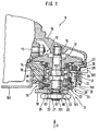
- the angle grinder shown in longitudinal section in Figure 1 9 has a housing 10, which is not shown electric drive motor with a drive shaft 11, one Angular gear 12 and a work spindle 13 receives.
- the Working spindle 13 is in a ball bearing 14 and a needle bearing 15, both designed as radial bearings, rotatably mounted.
- the needle bearing 15 is from the machine housing 10 and that Ball bearing 14 from a plastic bearing flange 16 added.
- the bearing flange 16 is on the machine housing 10 flanged and on his neck 160 designated outer circumference sits an angle grinder protection hood 161st
- the working spindle 13 stands axially with its free end 131 over the bearing flange 16 before. On this free end 131 sits a jig 17 which is a tool 18 in shape a cutting or grinding wheel.
- the tensioning device 17 comprises one on the free end 131 the work spindle 13 plugged in and rotatable with this and radially and axially fixed clamping flange 19 and a tension nut 20.
- the tension nut 20 is on a threaded portion 21 of the free end 131 of the work spindle screwed.
- the tool 18 is with a centering hole 22 on one on the end face of the Clamping flange 19 formed receiving pin 23 form-fitting attachable and non-positive by means of the clamping nut 20 against the annular end face 191 of the clamping flange 19 can be pressed.
- a washer 24 mounted between the clamping nut 20 and the Tool 18 is a washer 24 mounted.
- the work spindle 13 has a spindle lock 25 when actuating the hand lever 29 against rotation.
- the spindle lock 25 has an outside on the clamping flange 19 trained grooved collar 27 with a variety in equal angular distances apart, more radial Grooves 28 with a rectangular cross section, and one with the groove ring 27 interacting locking cams 32 with a hook-shaped Contour of its cam face 37 on (Fig. 2).
- the contour of the grooves 28 and the profile of the locking cam 32nd are coordinated so that the locking cam 32 when Engagement in the groove 28 when stationary or only slightly Speed of rotating work spindle 13, i.e.
- the clamping flange 19 and thus the work spindle 13 holds and in the undesired case, i.e. when the spindle lock is actuated while the motor is running, the locking cam 32 with minimal force and low Vibrations from the grooved ring 27 is rejected and the work spindle 13 can not hold on.
- This vote results due to the small difference in width of the cam support surface 37 compared to the width of the groove 28 of only about 1 mm.
- the locking cam 32 has too little time in Working direction of rotation of working spindle 13 and when actuated of the hand lever 29 as far as the groove base 45, that he can hold firmly in the groove 28 and the groove ring 27 together with the working shaft 13 for Can stop.
- the grooves 28 of the groove ring 27 point towards one in accordance with Figure 2 passing through the center of the work spindle 13 imaginary radial oblique, essentially parallel flanks 42, 44 and an essentially flat groove base 45.
- the flanks 42, 44 are to the right in the viewing direction, i.e. against the direction of rotation arrow 50 and opposite one through the center of the working spindle 13 radial ( Figure 2) inclined.
- the locking cam 32 is at the free end of a pivot pin 31 formed, which is rotatably mounted in the bearing flange 16.
- the axis of rotation 30 of the pivot pin 31 runs parallel to Working spindle 13.
- the pivot pin 31 is a right angle protruding hand lever 29 rotatably connected, the Hand lever 29, the pivot pin 31 and the locking cam 32 in several parts, are made in particular of plastic.
- the hand lever 29 is close to that facing away from the locking cam 32 End of the pivot pin 31 arranged, one end Pintle section 311 extends axially beyond the hand lever 29 continues and is supported in the bearing flange 16.
- On the front pivot pin portion 311 is a torsion spring trained return spring 33 pushed, one of which Spring end on the bearing flange 16 and its other spring end is fixed on the pivot pin 31.
- the return spring 33 is designed so that it the pivot pin tries to turn into a basic position in which the locking cam 32 is completely swung out of the groove 28 and immediately radially in front of the groove ring 27 on the clamping flange 19 stands at a distance.
- This basic position of the pivot pin 31 or locking cam 32 is. by a trained on the clamping flange 16 Stop 34 given to the hand lever 29 creates ( Figure 2).
- the hand lever 29 projects through a Opening 35 in the bearing flange 16 radially slightly above this out and carries a handle plate 291 on one side.
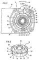
- FIG. 2 shows a top view of the angle grinder 9 from the side of the clamping flange 19 from the locking cams 32 as an elongated lever arm with on the facing away from the clamping flange 19, radially outer side straight or rounded Contour that beaks away on the hand lever 29, the radially inner side facing the clamping flange 19 a front edge 38 rounded off with a small radius of curvature in a flattened, preferably concave with the same Radius of curvature like the groove ring 27 curved cam face 37 with a rear end edge 38 'and there in one V-shaped recess 39 merges.
- the recess 39 is correct essentially with the contour of the left flank 42 of the groove 28 in the area of an acute-angled holding edge 41, that from the transition of the groove flank 42 into the circumferential curvature the groove ring 27 is formed.
- the clamping plate 62 has a preferably radially corrugated End face 621.
- the corrugated surface 621 is used for holding of the clamped, disc-shaped tool 18 with high surface pressure.
- the first is Locking nut 20 by means of a wrench, not shown to solve.
- the operator places a finger on the grip plate 291 of the hand lever 29 and pivots the hand lever 29 in the direction of arrow 26 according to FIG. 2 Pivot pin 31 clockwise against the force of the return spring 33.
- the locking cam 32 pivots into one of the Grooves 28 in the groove ring 27.
- the rounded one is supported Front edge 38 of the locking cam 32 against the right Groove flank 44 or its rounding 46 of the clamping flange 19.
- the rounding 46 and the end edge 38 are dimensioned such that , the greater the loosening torque on the clamping nut 20, the more the locking cam 32 holds on the flank 44.
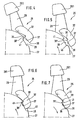
- FIGS. 4 to 7 enlarged Detail of the spindle lock 25 in different Working positions are shown in Figure 4, the neutral position of the locking cam 32 with respect to the groove 28 of the groove ring 27 with unactuated spindle lock 25 with the hand lever 29, the locking cam 32 and the grooved ring 27.
- Figure 5 shows the detent cam 32 when operated incorrectly, i.e. at Actuation of the spindle lock 25 in the direction of the arrow fast rotating output shaft 13 immediately after Reject at the groove 28.
- the easy rounded end edge 38 at the rounding 46 of the groove flank 44 has slipped so that the entry of the locking cam 32nd is prevented in the groove 28. They only become clear slightly smaller size of the locking cam 32 compared to the Nut 28.
- the locking cam 32 when actuated the spindle lock 25 only then from its support position on the radially outer edge of the groove rim 27 in the groove 28 can occur when the retaining edge 41 on the Recess 39 has arrived. But since in this position the Rounding 46 is only about 1 mm from the end face 38 is, they meet each other before the front edge 38 the Nutgrund 45 has reached and stopping at the Nutrand 44 can support.
- the locking cam 32 is therefore after a relatively short unsuccessful actuation swivel stroke at the rounding 46 rejected and undergoes a very short, repellent return stroke. This leads to a smooth, low-vibration reaction on the spindle lock 25 when operated incorrectly and results a corresponding gain in occupational safety.
- the Work spindle 13 can only be locked when their speed is sufficiently low.
- Figure 6 shows the position of the locking cam 32 locked in the groove 28 when stopping at a sufficiently slow speed working spindle 13 running in the direction of rotation, wherein the abrupt front edge 38 is sliding against the Groove edge 44 supports.
- the clamping nut 20 can be loosened are held without the spindle lock 25 actuated must be as long as the front edge 38 due to the loosening torque on the clamping nut 20 self-retaining on the groove flank 44 supports.
- the locking cam 32 can only be used relatively low force are pivoted and only thereby enter the groove 28 at a low speed of the groove ring 27. This is because when the locking cam 32 in the groove 28 can pivot only about 1 mm play between the Front edge 38 and the rounding 46 are present at the Overlap the locking cams 32 on its locking stroke Nutground 45 must have reached. This is 1 mm at working speed drive through the grooved collar 27 much faster than the front edge 38 can reach the groove base 45 and itself then stop there on the steep area of the groove flank 44 can. The fact that after only a short time with relatively small force triggerable swing stroke to the Rounding 46 of the further flanking flank 44 meets he rejected it, with little vibration and noise arise and cannot irritate the operator.
- Figure 7 shows that when tightening the clamping nut 20 the Working spindle 13 together with the spider 27 in reverse Direction as shown in Figure 6 and that a Continue turning the work spindle 13 when tightening the clamping nut 20 is prevented.
- the groove 27 follows her. If the hand lever 29 is actuated, the detent cam arrives 32 engages in the groove 28. The rear hooks Front edge 38 of the locking cam 32 below the holding edge 41 the groove flank 42 so that it is only then again can solve if the grooved ring 27 slightly against Clamping direction is turned back. Therefore, when tensioning the Clamping nut 20 of the hand lever 29 can only be actuated in a snap-in manner, the hand lever 29 then actuating Hand is free, for example to support the hand tool 9 when clamping tools.
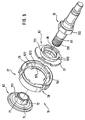
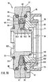
- FIGS. 8, 9 External hexagon 132 carrying work spindle 13 with the Main parts of the clamping flange 19, the support ring 63, the Groove ring 27 and the clamping plate 62.
- the support ring 63 is with its hexagon socket 36 rotatably on the hexagon socket 132 the work spindle 13 can be plugged on. It is supported in the assembly position axially on the grooved collar 27, this being limited compared to the support ring 63 is rotatable and radially engages over it.
- the support ring 63 carries axially adjacent to the hexagon socket 36 an inner double 721, which is the outer double 72 of the clamping plate 62 rotatably but axially displaceable embraces.
- the work spindle 13 carries one on its free end 131 Ring groove 81 for inserting a round ring 80 ( Figure 1), the the clamping flange 19 with axial play, but against loss securely holds onto the work spindle 13.
- the radially inner three latching raceways are on the groove ring 27 67 recognizable by a tooth-like radial after inside protruding stop 672 radially in each area slope 673 leading inwards and from there in a radial direction pass out recess 674 leading to the outside.
- the three rolling elements 68 can move radially according to FIG. 11, if the clamping flange 19 by turning the groove ring 27 is placed in its release position.
- Figure 9 clearly shows the left in the viewing direction Clamping plate 62 from behind, with its cylindrical central Cylinder connector 71 with a double 72 and with a Ring groove 711 is visible at the extreme end.
- the ring groove 711 is used for the engagement of a round ring 712 (FIG. 10) which the clamping flange 19 axially fixed to each other, so that arranged in the interior shown in the following figures Individual parts together with the grooved ring 27 and the Support ring 63 are captively held axially to each other.
- FIG. 10 shows a longitudinal section of the clamping flange 19 the round ring 712 on the cylinder neck 71 of the clamping plate 62, the position of the individual parts of the clamping flange 19 axially functionally secured to each other.
- the clamping plate 62 can be axially supported with respect to the support ring 63, around by the clamping nut 20 against the tool 18 directed axial clamping pressure.
- the clamping plate 62 is together with the support ring 63 opposite the work spindle 13 axially displaceable and non-rotatably connected.
- Support body 64 designed as a circular ring segment arranged in a supporting manner so that between the clamping plate 62nd and an annular groove is formed in the support ring 63.
- the ring collar 70 closes axially almost flush with the contour of the end face 191 of the Clamping plates 62.
- the grooved ring 27 sits axially with play between the clamping plate 62 and the support ring 63 and is rotatably arranged relative to both.
- the grooved rim 27 contains the detent raceway 67, which can be cylindrical, for example.
- the rolling element 68 corresponds to the radial outer peripheral surface of the support body 64 a corresponding Mating track 641.
- the support bodies 64 are on by means of the rolling elements guided and rolling the raceways 67 and 641 68 ( Figure 11) in the form of cylinders, acted upon radially.
- FIG. 11 shows three in the exemplary embodiment shown about the same circumferential angular distances from each other Rolling elements 68 which are concentric with the central axis Races 67, 641 are guided and in contact with the support bodies 64 on the one hand and the grooved ring 27 on the other stand.
- the grooved ring 27 is supported on the rolling Rolling elements 68 radially opposite the clamping plate 62 and the Support ring 63, a cam ring embossed from sheet metal with a barbed area in one axial recess 632 of the support ring 63 is anchored.
- the Cam ring 78 forms a receptacle for the springs 69 and a socket and a stop surface for the rolling elements 68.
- FIG. 11 shows everyone in the area of the latching track 67
- Rolling element 68 has a recess 674 assigned to it. This consists of a radial, recessed towards the outside Ball pocket open to the center in the locking raceway 67.
- Each recess 674 is designed so that when rolling the rolling element 68 and upon reaching the respectively assigned Recess 674 the rolling elements 68 radially outwards hike. This results in the said radial relief the support body 64 and, as a result, the axial relief between clamping plate 62 and support ring 63.
- At least one of the two end faces 65, 66, between which the axially wedge-shaped support body 64 in cross section are arranged with parallel to the side surfaces of the Support body 64 extending ring surfaces 65, 66 formed are.
- the support body 64 due to the bias by the clamping nut 20 to push radially outwards.
- the support body 64 point both on the axial side facing the annular surface 65 is, as well as on the opposite axial side corresponding to the course of the respective ring surface 65 or 66 Cross-sectional bearing surfaces 642 and 643, respectively on.
- the support bodies 64 follow the rolling bodies 68 radially outwards as soon as they snap into the recesses 674.
- clamping plate 62 and support ring 63 move axially have moved towards each other is the clamping pressure of the clamping flange 19 reduced so much compared to the clamped tool 18, that the clamping screw or clamping nut 20 easily can be released by hand from the work spindle 13.
- the grooved ring 27 carries a cam-like one for each rolling element 68 Stop 672, the tooth-like radially inward into the web of the respective upstream rolling element 68 protrudes and for this forms a form-fitting contact surface.
- the groove rim 27 designed as a sintered part bears on his End-to-end, cylindrical upper and lower ring collars 84, 85. From the upper ring collar 84 is the clamping plate 62 and from the lower ring collar 85 of the support ring 63 radially at least partially spread. Between the ring collars 84, 85 and the clamping plate 62 and the support ring 63 is in each case a sealing ring 86, 87 is arranged.
- the sealing rings 86, 87 serve to seal the interior of the clamping flange 19, the support ring 63, the clamping plate 62 and the grooved ring 27 is bounded. They also hold the grooved ring 27 at least axially in position with respect to the support ring 63.
- the support ring 63 and the clamping plate 62 have on the outer edge and deposited on the inner surfaces facing each other Shoulders on the stepped ring recordings for form the sealing rings 86, 87.
- the clamping plate 62 is on the tool 18 facing Side with an axially projecting locating pin 23, on which the disk-shaped tool 18 can be centered is.
- the receiving pin 23 is from a transverse slot 622 enforced, through which an assembly tool for disassembly the locking ring 80 in the annular groove 81 of the work spindle 13 is releasable to remove the clamping flange 19.
- the receiving pin 23 is the outside of a round ring 231, which for better centering of the tool 18 serves.
- the Cam ring 78 consists of an at least partially flat one Bechring, which is axially supported on the front ring surface 65 of the support ring 63 rests.
- Figures 11, 11 a to c show that the cam ring 78 on the Circumferential area over which the support bodies 64 extend, Has segments 781, in particular ring segments 781 which the support body 64 are supported axially.
- the circumferential angle extension of the individual segments 781 corresponds at least approximately that of each support body 64.
- the segments 781 of the cam ring 78 are at circumferential angles of the same size spaced from each other.
- the segments are 781 than from the plane of the flat, flat ring portion 782 of the Sheet metal part bent sheet metal sections formed. These sheet metal sections are at least approximately the same Angle bent up, under which the end face 65 of the support ring 63 runs, which is an axial support surface for the forms oblique segments 781.
- the cam ring 78 also has protruding axially to the support ring 63 facing securing parts 783, e.g. Noses, on.
- the securing parts 783 engage in assigned receptacles 632 in the form of axial blind holes in the support ring 63, so that the cam ring 78 is positive in the circumferential direction is coupled to the support ring 63.
- the securing parts 783 are at preferably equal circumferential angular intervals arranged from each other and formed as a rag, from the plane of the flat, flat ring section 782 of the cam ring 78 out approximately at a right angle downwards are turned and there into the open, assigned Intervene in holder 631.
- the cam ring 78 carries stops 784 bent radially on the outside, on the one hand the spring 69 and on the other hand the rolling elements Strike 68. These are across the path of the rolling elements 68 bent out of the cam ring 78, each Rolling element 68 there is a stop 784. Every stop 784 starts from and is from the flat ring section 782 bent several times at right angles, approximately in cross section a square or e.g. of a pipe so that it is in the path of the rolling elements 68 stands up. Shape and / or Size of each bent sheet metal cutout for the stops 784 are chosen at least so large that one side an associated rolling element 68 and from the opposite Side the associated end of the spring 69 securely supported are.
- the cam ring 78 carries stop parts radially on the inside 785, which protrude axially upwards and the support bodies 64 position radially in their position.
- the stop parts 785 are cut out of the cam ring 78 and of the are supported on the inclined end face 65 of the support ring 63, bent segments 781 separate tabs formed, who bent up and over the end face 65 are.
- the stop parts 785 are in the area existing circumferential gaps between two in the circumferential direction with successive segments 781 are formed.
- two stop parts 785 arranged in the circumferential direction have a distance from each other.
- a tongue-shaped sheet cutout 787 is formed, the radially inside in the space between two support bodies 64 protrudes axially upwards.
- This towering sheet metal cutout 787 is arranged approximately at the same circumferential point such as one arranged radially on the outside on the cam ring 78 Securing part 783.
- FIG. 11 c Details of the approximately tongue-shaped, bent sheet metal section 787 shows in particular FIG. 11 c.
- tab section 787 includes a bent one opposite it and radially outward end portion 788 on. In cross section, both form a lying V, the Opening points radially outwards.
- This roughly tongue-shaped, towering cut-out 787 forms a safety device for the spring 69 when mounting the clamping flange 19th
- cam ring 78 which is approximately like a rolling bearing cage is a simplification and cost reduction for the Clamping flange 19 reached.
- the cam ring 78 presses the Support ring 63 and the clamping plate 62 resiliently axially apart, so that the clamping flange 19 always automatically after setting the release position, its clamping position occupies, from which he again by turning the ring gear 27 can be brought into the release position.
- Figure 12 shows the grooved collar 27 as a detail, the contour the detent track 67 with the triple arranged Climbs 671, the driving stops 672, the Gradients 673 of approx. 15 ° and recesses 674 are recognizable.
Landscapes
- Engineering & Computer Science (AREA)
- Mechanical Engineering (AREA)
- Constituent Portions Of Griding Lathes, Driving, Sensing And Control (AREA)
- Finish Polishing, Edge Sharpening, And Grinding By Specific Grinding Devices (AREA)
Claims (10)
- Machine-outil à main comportant un outil (18) en forme de disque et un boítier (10) avec une broche porte-outil (13) dont l'extrémité libre (131) reçoit l'outil (18) entre une bride de serrage (19) installée de manière imperdable et solidaire en rotation sur la broche porte-outil et un écrou de serrage (20) ainsi qu'un dispositif de blocage de broche (25) pour bloquer en rotation la broche porte-outil (13), ce dispositif ayant une couronne à rainures (27) dans la bride de serrage (19), avec au moins une rainure (28) et un levier à main (29) muni d'une came d'accrochage (32), destinée à pénétrer dans au moins une rainure (28) à flancs de rainure (42, 44),
caractérisée en ce que
la bride de serrage (19) s'actionne à la main pour serrer et desserrer l'outil en forme de disque (18) et peut être mise dans une position de serrage et une position de desserrage, de sorte que la bride de serrage tournant dans le sens de rotation de travail, en fin de mouvement et jusqu'à une certaine vitesse de rotation de la broche porte-outil (13), est protégée contre l'accrochage lorsqu'on actionne le dispositif de blocage de broche (25), et en dessous de cette vitesse de rotation elle peut être mise en position de blocage par le dispositif de blocage de broche (25) et mise en position de desserrage. - Machine selon la revendication 1,
caractérisée en ce que
le dispositif de blocage de broche (25) peut être couplé à la couronne à rainures (27) de la bride de serrage (19) de la broche porte-outil (13), peut être engagé sans accrochage dans le sens de rotation actif et être couplé avec accrochage dans le sens opposé, la prise de la came d'accrochage (32) dans la rainure (28) étant exclue par sa forme et ses dimensions aussi longtemps que son arête frontale arrière (38') n'est pas arrivée au fond (42) de la rainure. - Machine selon la revendication 2,
caractérisée en ce que
l'arête frontale arrière (38') de la came d'accrochage (32) glisse sur la couronne à rainures (27) jusqu'à ce que la came d'accrochage (32) puisse pénétrer dans la rainure (28), et la surface frontale (37) de la came d'accrochage (32) est plus courte de 1 à 3 mm que la largeur de la rainure (28). - Machine selon la revendication 3,
caractérisée en ce que
la came d'accrochage (32) et la rainure (28) ont d'un côté des contours à angle vif et de l'autre des contours arrondis pour la coopération réciproque. - Machine selon la revendication 4,
caractérisée en ce qu'
au moins le flanc arrière des deux flancs de rainure (42, 44) est incliné par rapport à la direction radiale dans la direction opposée au sens de rotation actif (26) de la broche porte-outil (13), le premier flanc (42) dans le sens de rotation de travail (26) rejoint notamment par une arête de fixation (42) à arête vive et le second flanc (44) arrondi rejoint par un arrondi (46) le contour de la couronne à rainures (27), et
la came d'accrochage (32) comporte une surface frontale de came (37) qui chevauche avec accrochage l'arête de fixation (41) du flanc (42) lors du desserrage de l'écrou (20) et une arête frontale (38) arrondie contre laquelle s'appuie le second flanc de rainure (44), la came d'accrochage (32) étant plus étroite de 1 à 2 mm que la rainure (28). - Machine selon la revendication 1,
caractérisée en ce que
la rainure (28) a une profondeur de l'ordre de 3 à 5 mm, une largeur d'environ 5 à 10 mm et des rayons de l'ordre de 0, 5 à 1,2 mm, la partie arrondie (46) ayant un rayon de courbure d'environ 1,2 à 1,8 mm. - Machine selon l'une quelconque des revendications 2 ou 3,
caractérisée en ce que
la came d'accrochage (32) a un bras de levier plus long de 1/3 à 1/2 que le levier à main (29). - Machine selon l'une quelconque des revendications 2 ou 3,
caractérisée en ce que
la surface frontale de came (37) de la came d'accrochage (32) est inclinée par rapport au fond de rainure (45). - Machine selon l'une quelconque des revendications 2 ou 3,
caractérisée en ce que
le fond de rainure (27) est mobile en rotation de manière limitée par les cames (77, 79) servant de butées. - Machine selon l'une quelconque des revendications 2 ou 3,
caractérisée en ce que
le chemin d'accrochage (67) présente une pente (673) d'environ 15° qui constitue un point de poussée protégeant contre les fausses manoeuvres.
Applications Claiming Priority (3)
| Application Number | Priority Date | Filing Date | Title |
|---|---|---|---|
| DE19650365 | 1996-12-05 | ||
| DE19650365 | 1996-12-05 | ||
| PCT/DE1997/002282 WO1998024589A1 (fr) | 1996-12-05 | 1997-10-06 | Machine-outil a commande manuelle |
Publications (2)
| Publication Number | Publication Date |
|---|---|
| EP0942802A1 EP0942802A1 (fr) | 1999-09-22 |
| EP0942802B1 true EP0942802B1 (fr) | 2003-01-08 |
Family
ID=7813663
Family Applications (1)
| Application Number | Title | Priority Date | Filing Date |
|---|---|---|---|
| EP97926899A Expired - Lifetime EP0942802B1 (fr) | 1996-12-05 | 1997-10-06 | Machine-outil a commande manuelle |
Country Status (5)
| Country | Link |
|---|---|
| EP (1) | EP0942802B1 (fr) |
| KR (1) | KR20000057372A (fr) |
| CN (1) | CN1077481C (fr) |
| DE (2) | DE59709119D1 (fr) |
| WO (1) | WO1998024589A1 (fr) |
Cited By (2)
| Publication number | Priority date | Publication date | Assignee | Title |
|---|---|---|---|---|
| US7722444B2 (en) | 2005-05-13 | 2010-05-25 | Black & Decker Inc. | Angle grinder |
| US10818450B2 (en) | 2017-06-14 | 2020-10-27 | Black & Decker Inc. | Paddle switch |
Families Citing this family (21)
| Publication number | Priority date | Publication date | Assignee | Title |
|---|---|---|---|---|
| DE19831542A1 (de) * | 1998-07-14 | 2000-01-20 | Bosch Gmbh Robert | Handwerkzeugmaschine |
| DE10017981A1 (de) | 2000-04-11 | 2001-10-25 | Bosch Gmbh Robert | Werkzeugaufnahme |
| DE10029277A1 (de) * | 2000-06-14 | 2001-12-20 | Bosch Gmbh Robert | Handwerkzeugmaschine |
| ATE327863T1 (de) | 2002-01-10 | 2006-06-15 | Black & Decker Inc | Getriebegehäuse |
| US7343841B2 (en) | 2002-02-15 | 2008-03-18 | Black & Decker Inc. | Blade clamp assembly |
| DE10242737A1 (de) * | 2002-09-13 | 2004-04-01 | Robert Bosch Gmbh | System mit einer Werkzeugaufnahme |
| US7980325B2 (en) * | 2004-01-16 | 2011-07-19 | Credo Technology Corporation | Rotating shaft locking mechanism |
| PT1834733E (pt) * | 2006-03-13 | 2008-11-27 | Monti Werkzeuge Gmbh | Grupo de escovas e processo para o acabamento de uma superfície de uma peça a ser trabalhada com auxílio do grupo de escovas |
| CN101342677B (zh) * | 2007-07-11 | 2011-08-03 | 苏州宝时得电动工具有限公司 | 手持式动力工具 |
| DE102010007714B3 (de) * | 2010-02-12 | 2011-06-01 | Festool Gmbh | Hand-Werkzeugmaschine mit einem Positionserfassungsmittel für ihre Werkzeugaufnahme |
| DE102010039637A1 (de) * | 2010-08-23 | 2012-02-23 | Robert Bosch Gmbh | Handwerkzeugmaschine mit einem Spannhals |
| DE102010043182A1 (de) * | 2010-10-29 | 2012-05-03 | Robert Bosch Gmbh | Tragbare Werkzeugmaschine |
| DE102011003098A1 (de) * | 2011-01-25 | 2012-07-26 | Robert Bosch Gmbh | Werkzeugspannvorrichtung |
| DE102011076370A1 (de) * | 2011-05-24 | 2012-11-29 | Robert Bosch Gmbh | Werkzeugmaschinenbremsvorrichtung |
| CN103862350B (zh) * | 2012-12-12 | 2017-06-27 | 苏州宝时得电动工具有限公司 | 具有推杆式止动机构的角磨机 |
| DE102013200865A1 (de) | 2013-01-21 | 2014-07-24 | Robert Bosch Gmbh | Werkzeugmaschinenbremsvorrichtung |
| DE102015121305A1 (de) * | 2015-12-08 | 2017-06-08 | Festool Gmbh | Hand-Werkzeugmaschine |
| DE102016220343A1 (de) * | 2016-10-18 | 2018-04-19 | Robert Bosch Gmbh | Schnellspannvorrichtung für eine zumindest eine rotierend antreibbare Abtriebswelle aufweisende tragbare Werkzeugmaschine, insbesondere Winkelschleifmaschine |
| WO2018110856A1 (fr) * | 2016-12-16 | 2018-06-21 | 주식회사 미래텍 | Dispositif de rotation |
| CN114770314A (zh) * | 2022-01-20 | 2022-07-22 | 麦太保电动工具(中国)有限公司 | 一种整合旋转轴和法兰压板的结构及使用该结构的角磨机 |
| DE102022205095A1 (de) * | 2022-05-23 | 2023-11-23 | Robert Bosch Gesellschaft mit beschränkter Haftung | Werkzeugmaschinenvorrichtung, Werkzeugmaschine und System |
Family Cites Families (4)
| Publication number | Priority date | Publication date | Assignee | Title |
|---|---|---|---|---|
| GB8610431D0 (en) * | 1986-04-29 | 1986-06-04 | Kango Wolf Power Tools | Rotary power tools |
| DE3644441A1 (de) * | 1986-12-24 | 1988-07-07 | Bosch Gmbh Robert | Spanneinrichtung zum loesbaren befestigen eines werkzeuges, insbesondere einer scheibe |
| DE3824040C1 (en) * | 1987-02-21 | 1989-11-23 | Robert Bosch Gmbh, 7000 Stuttgart, De | Clamping device for axially clamping a tool, in particular a disk |
| DE4432973B4 (de) * | 1994-09-16 | 2009-10-01 | Robert Bosch Gmbh | Elektrische Handwerkzeugmaschine mit einer Spindelarretierung |
-
1997
- 1997-10-06 CN CN97180386A patent/CN1077481C/zh not_active Expired - Fee Related
- 1997-10-06 DE DE59709119T patent/DE59709119D1/de not_active Expired - Lifetime
- 1997-10-06 KR KR1019990704910A patent/KR20000057372A/ko not_active Ceased
- 1997-10-06 WO PCT/DE1997/002282 patent/WO1998024589A1/fr not_active Ceased
- 1997-10-06 EP EP97926899A patent/EP0942802B1/fr not_active Expired - Lifetime
- 1997-11-28 DE DE19752810A patent/DE19752810A1/de not_active Ceased
Cited By (4)
| Publication number | Priority date | Publication date | Assignee | Title |
|---|---|---|---|---|
| US7722444B2 (en) | 2005-05-13 | 2010-05-25 | Black & Decker Inc. | Angle grinder |
| US8087976B2 (en) | 2005-05-13 | 2012-01-03 | Black & Decker Inc. | Trigger assembly for angle grinder |
| US8087977B2 (en) | 2005-05-13 | 2012-01-03 | Black & Decker Inc. | Angle grinder |
| US10818450B2 (en) | 2017-06-14 | 2020-10-27 | Black & Decker Inc. | Paddle switch |
Also Published As
| Publication number | Publication date |
|---|---|
| DE19752810A1 (de) | 1998-06-10 |
| CN1077481C (zh) | 2002-01-09 |
| DE59709119D1 (de) | 2003-02-13 |
| KR20000057372A (ko) | 2000-09-15 |
| CN1239912A (zh) | 1999-12-29 |
| WO1998024589A1 (fr) | 1998-06-11 |
| EP0942802A1 (fr) | 1999-09-22 |
Similar Documents
| Publication | Publication Date | Title |
|---|---|---|
| EP0942802B1 (fr) | Machine-outil a commande manuelle | |
| EP0424388B1 (fr) | Agencement de serrage axial d'outils, notamment de meules | |
| DE69612854T2 (de) | Spannfutter | |
| DE3510605C2 (fr) | ||
| DE4341140C2 (de) | Ratschenschraubenschlüsselanordnung zum Antreiben eines Befestigungselements | |
| EP1213107B2 (fr) | Montage pour fixer un outil à un arbre d'entraînement et adapteur pour celui-ci | |
| DE69421850T2 (de) | Flanschverriegelung | |
| WO1988005386A1 (fr) | Dispositif de serrage pour le blocage axial d'un outil, notamment d'une meule | |
| CH691040A5 (de) | Spannfutter. | |
| DE3605569A1 (de) | Schluesselloses bohrfutter sowie verfahren zur herstellung von schluessellosen bohrfuttern | |
| EP0623413A1 (fr) | Dispositif de serrage rapide pour lames de scie sauteuse | |
| EP2115822B1 (fr) | Connecteur à fiches coudé à direction de départ variable | |
| DE69221887T2 (de) | Nutfräse mit schneideeinsätzen gespannt durch exzenter oder nocken | |
| DE3031216A1 (de) | Spannfutter fuer gewindebohrer. | |
| DE10115635C1 (de) | Handwerkzeugmaschine mit einer Schutzhaube | |
| DE69421131T2 (de) | Schraubenschlüssel | |
| EP1211005A1 (fr) | Mandrin | |
| DE19831542A1 (de) | Handwerkzeugmaschine | |
| DE19650364A1 (de) | Handwerkzeugmaschine | |
| EP2260974B1 (fr) | Support de pièce usée pour une rectifieuse plane | |
| DE29616862U1 (de) | Drehsicherung für ein drehend gelagertes Werkzeug eines Arbeitsgerätes | |
| DE4426969B4 (de) | Handwerkzeugmaschine mit einer ein scheibenförmiges, lösbar befestigtes Werkzeug tragenden Arbeitsspindel | |
| DE3912493C2 (fr) | ||
| EP0697268A1 (fr) | Dispositif de verrouillage reversible pour une poignée de réglage tournable | |
| DE9305188U1 (de) | Schnellspannvorrichtung für Stichsägeblätter |
Legal Events
| Date | Code | Title | Description |
|---|---|---|---|
| PUAI | Public reference made under article 153(3) epc to a published international application that has entered the european phase |
Free format text: ORIGINAL CODE: 0009012 |
|
| 17P | Request for examination filed |
Effective date: 19990705 |
|
| AK | Designated contracting states |
Kind code of ref document: A1 Designated state(s): DE FR GB IT |
|
| 17Q | First examination report despatched |
Effective date: 20010427 |
|
| GRAG | Despatch of communication of intention to grant |
Free format text: ORIGINAL CODE: EPIDOS AGRA |
|
| GRAG | Despatch of communication of intention to grant |
Free format text: ORIGINAL CODE: EPIDOS AGRA |
|
| GRAH | Despatch of communication of intention to grant a patent |
Free format text: ORIGINAL CODE: EPIDOS IGRA |
|
| GRAH | Despatch of communication of intention to grant a patent |
Free format text: ORIGINAL CODE: EPIDOS IGRA |
|
| GRAA | (expected) grant |
Free format text: ORIGINAL CODE: 0009210 |
|
| AK | Designated contracting states |
Kind code of ref document: B1 Designated state(s): DE FR GB IT |
|
| PG25 | Lapsed in a contracting state [announced via postgrant information from national office to epo] |
Ref country code: IT Free format text: LAPSE BECAUSE OF FAILURE TO SUBMIT A TRANSLATION OF THE DESCRIPTION OR TO PAY THE FEE WITHIN THE PRESCRIBED TIME-LIMIT;WARNING: LAPSES OF ITALIAN PATENTS WITH EFFECTIVE DATE BEFORE 2007 MAY HAVE OCCURRED AT ANY TIME BEFORE 2007. THE CORRECT EFFECTIVE DATE MAY BE DIFFERENT FROM THE ONE RECORDED. Effective date: 20030108 |
|
| REG | Reference to a national code |
Ref country code: GB Ref legal event code: FG4D Free format text: NOT ENGLISH |
|
| REF | Corresponds to: |
Ref document number: 59709119 Country of ref document: DE Date of ref document: 20030213 Kind code of ref document: P |
|
| GBT | Gb: translation of ep patent filed (gb section 77(6)(a)/1977) |
Effective date: 20030402 |
|
| ET | Fr: translation filed | ||
| PLBE | No opposition filed within time limit |
Free format text: ORIGINAL CODE: 0009261 |
|
| STAA | Information on the status of an ep patent application or granted ep patent |
Free format text: STATUS: NO OPPOSITION FILED WITHIN TIME LIMIT |
|
| 26N | No opposition filed |
Effective date: 20031009 |
|
| PG25 | Lapsed in a contracting state [announced via postgrant information from national office to epo] |
Ref country code: FR Free format text: LAPSE BECAUSE OF NON-PAYMENT OF DUE FEES Effective date: 20040630 |
|
| REG | Reference to a national code |
Ref country code: FR Ref legal event code: ST |
|
| PGFP | Annual fee paid to national office [announced via postgrant information from national office to epo] |
Ref country code: GB Payment date: 20091023 Year of fee payment: 13 |
|
| GBPC | Gb: european patent ceased through non-payment of renewal fee |
Effective date: 20101006 |
|
| PG25 | Lapsed in a contracting state [announced via postgrant information from national office to epo] |
Ref country code: GB Free format text: LAPSE BECAUSE OF NON-PAYMENT OF DUE FEES Effective date: 20101006 |
|
| REG | Reference to a national code |
Ref country code: DE Ref legal event code: R084 Ref document number: 59709119 Country of ref document: DE Effective date: 20111230 |
|
| PGFP | Annual fee paid to national office [announced via postgrant information from national office to epo] |
Ref country code: DE Payment date: 20151215 Year of fee payment: 19 |
|
| REG | Reference to a national code |
Ref country code: DE Ref legal event code: R119 Ref document number: 59709119 Country of ref document: DE |
|
| PG25 | Lapsed in a contracting state [announced via postgrant information from national office to epo] |
Ref country code: DE Free format text: LAPSE BECAUSE OF NON-PAYMENT OF DUE FEES Effective date: 20170503 |