EP0942890B1 - Längenanpassung von abschnittslängen von druckbahnen - Google Patents
Längenanpassung von abschnittslängen von druckbahnen Download PDFInfo
- Publication number
- EP0942890B1 EP0942890B1 EP97952887A EP97952887A EP0942890B1 EP 0942890 B1 EP0942890 B1 EP 0942890B1 EP 97952887 A EP97952887 A EP 97952887A EP 97952887 A EP97952887 A EP 97952887A EP 0942890 B1 EP0942890 B1 EP 0942890B1
- Authority
- EP
- European Patent Office
- Prior art keywords
- web
- printing
- cycle lengths
- length
- Prior art date
- Legal status (The legal status is an assumption and is not a legal conclusion. Google has not performed a legal analysis and makes no representation as to the accuracy of the status listed.)
- Expired - Lifetime
Links
Images
Classifications
-
- B—PERFORMING OPERATIONS; TRANSPORTING
- B65—CONVEYING; PACKING; STORING; HANDLING THIN OR FILAMENTARY MATERIAL
- B65H—HANDLING THIN OR FILAMENTARY MATERIAL, e.g. SHEETS, WEBS, CABLES
- B65H23/00—Registering, tensioning, smoothing or guiding webs
- B65H23/04—Registering, tensioning, smoothing or guiding webs longitudinally
- B65H23/18—Registering, tensioning, smoothing or guiding webs longitudinally by controlling or regulating the web-advancing mechanism, e.g. mechanism acting on the running web
- B65H23/188—Registering, tensioning, smoothing or guiding webs longitudinally by controlling or regulating the web-advancing mechanism, e.g. mechanism acting on the running web in connection with running-web
- B65H23/1882—Registering, tensioning, smoothing or guiding webs longitudinally by controlling or regulating the web-advancing mechanism, e.g. mechanism acting on the running web in connection with running-web and controlling longitudinal register of web
- B65H23/1886—Synchronising two or more webs
-
- B—PERFORMING OPERATIONS; TRANSPORTING
- B65—CONVEYING; PACKING; STORING; HANDLING THIN OR FILAMENTARY MATERIAL
- B65H—HANDLING THIN OR FILAMENTARY MATERIAL, e.g. SHEETS, WEBS, CABLES
- B65H23/00—Registering, tensioning, smoothing or guiding webs
- B65H23/04—Registering, tensioning, smoothing or guiding webs longitudinally
-
- B—PERFORMING OPERATIONS; TRANSPORTING
- B65—CONVEYING; PACKING; STORING; HANDLING THIN OR FILAMENTARY MATERIAL
- B65H—HANDLING THIN OR FILAMENTARY MATERIAL, e.g. SHEETS, WEBS, CABLES
- B65H2511/00—Dimensions; Position; Numbers; Identification; Occurrences
- B65H2511/50—Occurence
- B65H2511/51—Presence
- B65H2511/512—Marks, e.g. invisible to the human eye; Patterns
-
- B—PERFORMING OPERATIONS; TRANSPORTING
- B65—CONVEYING; PACKING; STORING; HANDLING THIN OR FILAMENTARY MATERIAL
- B65H—HANDLING THIN OR FILAMENTARY MATERIAL, e.g. SHEETS, WEBS, CABLES
- B65H2701/00—Handled material; Storage means
- B65H2701/10—Handled articles or webs
- B65H2701/18—Form of handled article or web
- B65H2701/186—Several articles or webs processed together
- B65H2701/1864—Superposed webs
Definitions
- the present invention relates to a method for control or regulation of a period length of at least one printing path, which is a periodically repeating with the period length Has patterns, and one for performing such Device suitable for the method.
- a method and a corresponding device can be found in document EP-A-0 463 213.
- printing web extends here to any for processing by means of printing machines or finishing machines suitable web of any material.
- printing machines come for example Sheets of paper-like material and in particular Paper webs into consideration.
- the Period length of the printing web (register length) is here by the processing period length of the respective processing station determined, for example by the circumferential length of the Printing cylinder of a rotary printing machine.
- a print path already structured by sections must be one subsequent processing station "in phase” in any case are supplied, d. H. on the one hand, the frequency, with which the sections of the printing web into the processing station run equal to their processing frequency, and on the other hand is through the processing station at any time the processing period the relative position of the sections the printing path (register).
- register control which ensures "in-phase” feeding of the printing web, by the "phase”, i.e. H. the location of the sections on the Print path relative to the processing station in a particular one Time within the processing period, before the processing station is measured and depending on the measurement result the processing frequency of the processing station accordingly something is reduced or enlarged.
- a printing web first becomes a Roll is wound up to later be unwound from this roll and to be further processed (off-line finishing), as is often necessary for economic reasons, so the period length of the orbit can become unpredictable Change manner, for example depending on the storage period, storage temperature or humidity. Can too the period length vary within the same web roll, for example if after a certain storage period a freshly printed web roll in this web changes the moisture profile in the radial direction.
- a method for control or regulation a period length of at least one along a track current and one in the web running direction with the Period length showing a periodically repeating pattern Printing path is suggested, taking one to achieve a desired one Period length of the printing web at the beginning of the web running section more or less moisturized.
- the invention is based on the finding that the length of a section on a printing path or the period length change by moistening this print web, in general can enlarge. Knowing the relationship between the Degree of moistening of the printing web and the resulting Changing the length of a section is therefore possible set the desired period length of the printing path. In particular it is possible to change the period lengths of different print paths, which should be merged, to adapt to each other, so that these tracks are merged into register can do what was previously not possible with off-line finishing.
- the period length adapts the printing webs to one another, if necessary, adjusts to one another.
- the period lengths of the different printing paths must be the same be or correspond to each other in such a way that they are in proportion integers.
- the printing webs Have sections whose section lengths differ from printing web to differentiate printing web, but the sections all printing webs each from one or more, adjacent subsections more uniform Length are composed.
- the period lengths the different printing paths are not adjusted, but adapted to each other, such that the lengths of the to Sub-sections to be covered exactly aligned become.
- the current period lengths of these printing webs determined and depending on the determined period lengths the respective desired period lengths or target period lengths specifies.
- the desired period lengths or Target period lengths individually to the originally available Period lengths of the print paths to be merged adjusted.
- the Print path with the comparatively largest value of the current one Period length at the beginning of the railway line is not or only very little moisturized.
- the period lengths of the printing paths are to be aligned with each other, so this becomes the printing web with the largest value of the current period length at the beginning the track.
- the period lengths of the printing webs but to adapt to each other, such that each corresponding subsections of the printing web sections of different lengths brought to the same subsection length will be the printing web with the greatest value of current subsection length at the beginning of the track his.
- dampening rollers can be tangential Strip the passing printing web and wet it, whereby the degree of wetting by means of the speed of rotation of the rollers or changing the web wrap angle is adjustable.
- direct spraying of the printing web is preferred, whereby a particularly smooth and easy way to controlling application of a dampening medium to the printing web is possible.
- the efficiency and uniformity of humidification is increased even further if you have an electrical Field created in the spray area.
- This electric field can, for example, lead to the fact that the printing web in Spray area electrically charges and thus the humidification medium attracts.
- the device according to the invention comprises a moistening device for the printing web as well as one to the dampening device connected control unit that controls the humidifier to achieve the desired period length or the target period length.
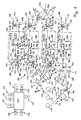
- the device shown comprises four essentially identically constructed railroad tracks 101-104, along their respective a printing web drawn from a printing web roll 110 111-114 is running.
- the precise registration of these four Lanes 111-114 is particularly problematic because of it are webs of different roles, d. H. Not to split partial webs of one and the same web, but to Paths that come together as part of an off-line finishing should be processed further and accordingly not period lengths that are precisely matched or varied (Register lengths).
- the device shown in Fig. 1 is used to measure the period lengths P1-P4 of the four printing paths 111-114 on a uniform Period length P 'at the end of the railway lines 101-104 bring to.
- Each of the lanes 111-114 runs from the respective one Printing web roll 110 successively in the direction of arrow 115 a first measuring device 128 'for measuring its current one Period length at the beginning of the web run, a first web drive device 120 for pulling the web from the respective Roller 110, a humidifier 122 for controlled Moisten the web, a compensator in the form of a Print web storage 124, which has a variable print web length stores, a second web drive device 126 and one second measuring device 128 for measuring the end of the web running section existing period length P1'-P4 'and the relative Position of the sections on the respective web in the longitudinal direction of the web (Passer).
- the lanes are merged in the area of the deflection rollers 144 on the right side of FIG. 1.
- control unit 130 which signals from the just receives mentioned components or outputs signals to them.
- each the period length of the Web is measured and this web then through the humidifier 122 more or less humidified accordingly is going to be one for all at the end of railroad tracks 101-104 to obtain four lanes 111-114 of uniform period length P '. It is also conceivable that the individual period lengths P1-P4 already knows and thus on the measuring devices 128 'at the beginning the railroad tracks 101-104 can do without.
- the measuring devices are used 128 'at the beginning of the railway lines 101-104, the period lengths P1-P4 of the lanes 111-114 and measure the At the end of the railway lines 101-104 desired, uniform Period length P 'to be determined. This determination is made by the Control unit 130 performed, which the necessary signals of measuring devices 128 'via respective lines 170' receives.
- the Control unit 130 performed, which the necessary signals of measuring devices 128 'via respective lines 170' receives.
- the web with the greatest value of the period length only slightly or not at all moistened will and as a uniform, at the end of the railway lines 101-104 desired period length their period length or a slightly longer period length is set.
- the latter Measure gives some leeway in terms that a slight reduction in this maximum period length is unproblematic at the beginning of the track.
- the print web storage 124 take over also the function of a "register control" by the relative position of the sections of the respective track in The longitudinal direction of the web considered at the corresponding relative position adjust the sections of the other printing webs so that the sections are not just of uniform length the device leave, but also congruent.
- This adjustment of the relative section positions is done by Control of the print web storage 124 by the control unit 130 performed.
- the control unit 130 receives the necessary for this Information about the actual, current relative Positions of the sections on the different printing paths 111-114 from the respective measuring devices 128 to the Ends of the railway lines 101-104. These measuring devices 128 transmit this information via appropriate lines 170 to the control unit 130.
- the print web storage 124 of the web running routes 101-103 comprise one stationary one at a time in the direction of web travel Storage pulley 146 and a movable storage pulley 148, which is relative to the stationary storage pulley 146 with an adjustment drive in the direction of the double arrow 152 can be moved, this movement being a corresponding one Change in the currently saved path length.
- This adjustment drive can generally by any, to this Suitable means can be implemented for the purpose, for example by an electrically operated spindle drive.
- an electrically operated spindle drive In the illustrated An example is the adjustment drive with a Cylinder-piston unit 158 symbolizes the movement the movable storage pulley 148 by means of a Piston rod 156 causes.
- the cylinder-piston unit 158 is thereby via a line 160 from the control unit 130 to Controlled setting of the web length to be saved.
- the print web storage 124 of the web run section 104 has in the Difference to the print web memories 124 described above to increase the storage capacity or to reduce the Inertia two movable storage pulleys 148 on the common movement relative to two stationary storage pulleys 146 with each other and with the piston rod 156 the cylinder-piston unit 158 are connected.
- the period lengths P1'-P4 'at the output of the corresponding Print web storage 124 have due to the above described Regulation on a uniform period length P '. If relative shifts the one at the end of the railway lines 101-104 merged lanes 111-114 are possible, one can current phase alignment of the tracks 111-114 using the Print path storage 124 take place. This coincides with the sections of the merged tracks over a greater length. Are relative displacements of the merged paths at all not or only to a very small extent (e.g. because of subsequent gluing of the sheets) is possible the phase adjustment by the printing path memory 124, so that the phase adjustment only by that described above targeted web moistening can take place. With a bond the lanes 111-114 after their merging must be considered that in practice mostly a slight possibility of relative displacement of tracks 111-114, so that the control the print path memory 124 slightly for phase adjustment can contribute.
- each path runs through 111-114 following the corresponding print web storage 124 the second web drive device 126, which has a certain maintains the necessary web tension for safe web guiding.
- the first web drive device 120 generally runs with constant speed and non-slip.
- the second Web drive device 126 runs with a slightly larger one Speed regulated depending on the desired Web tension as well as with a slight slip to the required web tension without considerable regulation effort maintain. Deviating from the illustrated embodiment it is of course possible to use the web drive device 120 in the course of the web behind the corresponding moistening device 122 to arrange.
- the web drive devices 120 and 126 each include two drive rollers 132, between which the respective printing web is passed and which from a drive unit 134 are driven in the form of a motor by the control unit 130 is controlled via a line 136.
- Fig. 1 are the movable storage pulleys 148 viewed in their direction of movement 152 between two Position detectors 162 and 164 of print web accumulator 124. These detectors 162, 164 give signals over lines 166 or 168 to the control unit 130 when the movable Storage roller 148 which corresponds to the detectors 162 and 164, respectively Positions reached. These positions correspond each currently saved path lengths at which the Print web storage 124 is relatively filled or relatively emptied is. For example, that by the position detector 162 certain default values are 3/4 of the web storage capacity, during that determined by position detector 164 Default value selected as a 1/4 of the web storage capacity can be.
- this detector 162 If the currently saved path length corresponds to the position of the first position detector 162 predetermined maximum value exceeds, this detector 162 outputs a signal to the Control unit 130, which is then the first web drive device 120 drives to a lower web speed, so that the speed at the beginning of the track runs reduced and subsequently the currently in the print web memory 124 saved path length is reduced.
- Detector 164 when falling below the value specified by this detector Minimum value of the saved path length a signal to the control unit 130, whereupon this the the web running speed determining drive device, in the illustrated Case the web drive device 120, in reverse controls to gradually increase the saved path length again increase.
- the webs could be moistened 111-114 also depending on the respective currently in the web lengths stored in the print web memories 124 are controlled become.
- the control unit 130 can be exceeded of the maximum value or falling below the minimum value the corresponding web length the corresponding moistening device 122 for the corresponding correction of the current Activate period length.
- the measuring devices 128 and 128 'can for example, by known photoscanner units can be formed.
- Photoscanner units are suitable, period lengths or Section lengths of printing webs and relative section positions in the longitudinal direction of the printing path by means of it Print marks on the printing web or by means of the on the To determine the print path of the print image itself.
- these photoscanner units serve as a component a register control only to the processing frequency a subsequent processing station that the printing web is fed "in phase", so that the processing step performed by this processing station at the designated position or the intended section of the track is executed.
- the measuring device 128 serves at the end of the However, web running routes 101-104 are not only for measuring the relative Section positions, but also to control the current period length at the end of the respective web run. One of these measured period lengths is connected via a line 170 corresponding signal to the control unit 130 issued to web drive units and web stores, their arrangement and number adapted to the respective purpose can be controlled appropriately.
- the dampening devices 122 of the web running tracks 101 and 102 include one after the other in the web running direction Spray units each with a spray head 140 and one High voltage unit 142 on the associated spray head 140 opposite side of the corresponding web 111 or 112.
- a moistening medium is in each case in the simplest case, water, towards the spray head 140 Sprayed on the web side, the impact of the water droplets is promoted on the web by the fact that the same in Spray area by the associated high voltage unit 142 is electrically charged.
- Particularly advantageous humidification devices of this type are described below with reference to FIG. 3 to 5 described in more detail.
- the dampening devices 122 of the web running tracks 103 and 104 are each formed by roller assemblies, each a dampening roller partially immersed in a dampening medium 105 which contain the humidification medium transfers to the respective printing web.
- the control of the degree the moistening of the respective printing web 113 or 114 yourself by adjusting the rotational speed of this Dampening rollers 105 and / or the wrap angle vary, with which the printing web wraps around this roller 105.
- Web moistening and the associated change in section length creates the opportunity along a track a printing path of a subsequent processing station to ensure that no or very little "machining slip" (in a printing press, e.g. slip between the printing path and the printing cylinder) is required, around the machining frequency, d. H. in the case of a rotary printing press the rotation frequency of the impression cylinder to which Frequency of the sections entering the processing station adapt. This can be particularly advantageous in cases in which such a slip is undesirable.
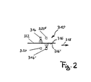
- this web 312 consists of paper and runs along a track in a print shop.
- a spray head 314 sprays an upper web side 316 with one Humidification medium like water, while one versus a lower one Web side 316 'and behind in web direction (arrow 318) the second spray head arranged after the first spray head 314 314 'in a corresponding manner moistens the lower web side 316'.
- To achieve a uniform and efficient humidification web 312 is one for each spray head 314 and 314 ' Assigned electrode arrangement 320 or 320 ', which in each case Spray area of the spray heads 314 an electric field generated and the web 312 in the respective spray area electrically charges, causing the impingement of particles of the dampening medium, here water droplets, on the corresponding one Track side 316 or 316 'is promoted.
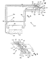
- Fig. 3 is the humidification device shown in Fig. 2 shown in more detail, the IV marked area the area shown in Fig. 2 corresponds.
- a humidifying medium 330 becomes a reservoir 332 by means of a pump 334 via a line 336, which one at 338 located branch to the spray heads 314 and 314 'promoted.
- a control unit controls the pump 334 and enables the setting of a desired pressure of the the dampening medium reaching the spray heads, whereby the Degree of dampening of the printing web 312 in a large area can be adjusted.
- the Control unit also, for example, electrically operated valve means in the spray heads to control the amount of sprayed To change the dampening medium.
- humidification device 310 becomes a humidification medium constant pressure to spray heads 314 and 314 ' whereby the structure in the area of pressure generation and Area of the spray heads 314 simplified.
- each spray head 314 and 314 ' each associated with two baffle plates 340 movable relative to each other, located between a spray head 314 or 314 'and the printing web 312 are located and serve in a controlled manner Part of that from the respective spray head 314 or 314 'dampening medium emerging from the printing web 312 withholding.
- the baffle plates 340 serve as panels with variable "passage” and can be driven by means not shown (e.g. Cylinder-piston units) in the direction of the double arrow 342 be moved relative to each other.
- baffle plates 340 are trough-shaped and leave in the example shown, only the part of the respective Spray head outgoing dampening medium on the Track 312, which is between these baffles 340 passes through.
- baffles associated with the lower spray head 314 ' 340 dampening medium retained falls on one below the baffle 340 arranged collection tray 348 and in a corresponding manner via a further return line 350 passed back to the reservoir 332.
- FIG. 4 shows the humidification device according to FIG. 4 in one perspective view, wherein in Fig. 4 three spray heads 314 and 314 ', respectively, to illustrate like using a variety of spray heads Uniformity of humidification can further improve.
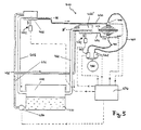
- the humidifier 410 includes an upper spray head 414 and a lower spray head 414 ', each of which, on the one hand, comprises humidifying medium 430 the storage container 432 and on the other hand additionally Compressed air, starting from one compressed air source 460 over two Compressed air valves 462 and two compressed air lines 464, supplied becomes. This is a particularly fine commissioning of the Humidification medium possible. However, the expense is disadvantageous to provide the compressed air.
- the Humidification medium 430 via line 438 initially in buffer 466 or 466 ' is promoted, which in its Height are adjustable.
- These buffers 466 are each provided with an overflow line 468, which is a return of the humidification medium from the respective buffer 466 or 466 'cause back to reservoir 432 as soon as the liquid level in each case predetermined levels N or N ' exceeds.
- the two buffers 466 and 466 ' are via supply lines 470 each with the associated spray heads 414 or 414 'connected and supply this humidification medium with a given by the respective liquid level N or N ' hydrostatic pressure.
- N not necessarily a movement of the relevant buffer is necessary, rather is sufficient with the corresponding Design a change in the corresponding liquid level even by changing the fill level in the buffer stores.
- the hydrostatic is generally Select a higher pressure at the lower spray head 414 ' be d. H. the associated level N 'then becomes higher than that other levels N must be arranged.
- a control unit 474 is provided to control the pump 434 two compressed air valves 462, the two spray heads 414 and two lifting devices 472 for controlled lifting and lowering of the to control two buffers 466.
- These lifting devices can, for example, by a cylinder-piston unit be formed.
- it is also conceivable that instead of these lifting devices from the control unit 474 means for Setting the liquid level in the buffer stores 466 can be controlled, whereby, as described above, the change the hydrostatic pressures is also made possible.
Landscapes
- Inking, Control Or Cleaning Of Printing Machines (AREA)
- Dot-Matrix Printers And Others (AREA)
Abstract
Description
- Fig. 1
- eine schematische Darstellung einer Vorrichtung zur Regelung der Periodenlängen von vier, jeweils längs einer Bahnlaufstrecke laufenden Druckbahnen, wobei die Periodenlängen einander angeglichen werden und die Druckbahnen passergenau zusammengeführt werden,
- Fig. 2
- eine schematische Darstellung einer Befeuchtungsvorrichtung mit zwei in Bahnlaufrichtung aufeinanderfolgenden Sprüheinheiten,
- Fig. 3
- eine schematische Darstellung einer weiteren Befeuchtungsvorrichtung, welche mit einem Blendensystem zur Steuerung des Befeuchtungsgrads ausgestattet ist,
- Fig. 4
- eine detailliertere, perspektivische Darstellung eines Teils der Befeuchtungsvorrichtung gemäß Fig. 3, und
- Fig. 5
- eine Darstellung einer Befeuchtungsvorrichtung zum Befeuchten einer diese Vorrichtung passierenden Druckbahn.
Claims (16)
- Verfahren zur passergenauen Zusammenführung von mehreren Druckbahnen (111-114), wobei die Druckbahnen (111-114) jeweils längs einer Bahnlaufstrecke (101-104) laufen, jeweils ein in Bahnlaufrichtung sich mit einer Periodenlänge (P1-P4) periodisch wiederholendes Muster aufweisen, und anschließend an die jeweiligen Bahnlaufstrecken (101-104) zur gemeinsamen Bearbeitung zusammengeführt werden,
dadurch gekennzeichnet, daß man die Periodenlängen (P1-P4) der Druckbahnen (111-114) aneinander anpaßt, indem man zur Erzielung von gewünschten Periodenlängen (P1'-P4') die Druckbahnen (111-114) am Anfang der Bahnlaufstrecken (101-104) jeweils mehr oder weniger stark befeuchtet. - Verfahren nach Anspruch 1, dadurch gekennzeichnet, daß man die Periodenlängen (P1-P4) der Druckbahnen (111-114) aneinander angleicht.
- Verfahren nach Anspruch 1 oder 2, dadurch gekennzeichnet, daß man die Periodenlängen (P1-P4) der Druckbahnen (111-114) regelt.
- Verfahren nach Anspruch 3, dadurch gekennzeichnet, daß man am Ende der jeweiligen Bahnlaufstrecken (101-104) die momentanen Periodenlängen (P1'-P4') ermittelt und mit Soll-Periodenlängen vergleicht, und daß man in Abhängigkeit von den Differenzen zwischen momentanen Periodenlängen (P1'-P4') am Ende der jeweiligen Bahnlaufstrecken und Soll-Periodenlängen die Druckbahnen (111-114) am Anfang der Bahnlaufstrecken (101-104) jeweils mehr oder weniger stark befeuchtet.
- Verfahren nach einem der vorhergehenden Ansprüche, dadurch gekennzeichnet, daß man am Anfang der Bahnlaufstrecken (101-104) die momentanen Periodenlängen (P1-P4) mehrerer Druckbahnen (111-114) ermittelt und abhängig von diesen ermittelten Periodenlängen (P1-P4) die jeweiligen, gewünschten Periodenlängen (P1'-P4') bzw. Soll-Periodenlängen festlegt.
- Verfahren nach Anspruch 5, dadurch gekennzeichnet, daß man die Druckbahn (111-114) mit dem vergleichsweise größten Wert der momentanen Periodenlänge (P1-P4) am Anfang der Bahnlaufstrecke (101-104) nicht befeuchtet.
- Verfahren nach einem der vorhergehenden Ansprüche, dadurch gekennzeichnet, daß man die Druckbahn (111-114) durch einen Druckbahnspeicher (124) mit variabler gespeicherter Bahnlänge führt, im Bahnverlauf nach dem Druckbahnspeicher (124) die relative Position von Abschnitten auf der Druckbahn (111-114) in Bahnlängsrichtung mißt und in Abhängigkeit von dieser Position der Abschnitte die momentan gespeicherte Bahnlänge verändert.
- Verfahren nach Anspruch 7, dadurch gekennzeichnet, daß man dann, wenn die momentan gespeicherte Bahnlänge einen oberen Vorgabewert überschreitet oder einen unteren Vorgabewert unterschreitet, die Druckbahn (111-114) am Anfang der Bahnlaufstrecke (101-104) entsprechend mehr oder weniger stark befeuchtet.
- Verfahren nach einem der vorhergehenden Ansprüche, dadurch gekennzeichnet, daß man die Druckbahn (111-114) durch Besprühen befeuchtet.
- Verfahren nach Anspruch 9, dadurch gekennzeichnet, daß man ein elektrisches Feld im Sprühbereich erzeugt.
- Vorrichtung zur Durchführung des Verfahrens nach einem der vorhergehenden Ansprüche, umfassend mehrere Befeuchtungsvorrichtungen (122) für die Druckbahnen (111-114), eine an die Befeuchtungsvorrichtungen (122) angeschlossene Steuer-/Regeleinheit (130), die die Befeuchtungsvorrichtungen (122) zur Erzielung der gewünschten Periodenlängen (P1'-P4') bzw. der Soll-Periodenlängen ansteuert, sowie Mittel (144) zur Zusammenführung der Druckbahnen am Ende der Bahnlaufstrecken (101-104).
- Vorrichtung nach Anspruch 11, dadurch gekennzeichnet, daß jeweils eine Meßeinrichtung (128) am Ende der Bahnlaufstrecken (101-104) vorgesehen ist, die ein die momentane Periodenlänge (P1'-P4') angebendes Signal an die Steuer-/Regeleinheit (130) abgibt.
- Vorrichtung nach Anspruch 11 oder 12, dadurch gekennzeichnet, daß jeweils eine Meßeinrichtung (128') am Anfang der Bahnlaufstrecken (101-104) vorgesehen ist, die ein die momentane Periodenlängen (P1-P4) angebendes Signal an die Steuer-/Regeleinheit (130) abgibt.
- Vorrichtung nach einem der Ansprüche 11 bis 13, gekennzeichnet durch wenigstens einen Druckbahnspeicher (124) mit variabler gespeicherter Bahnlänge sowie durch eine jeweils nachfolgende Positionsmeßeinrichtung (128) zur Messung der relativen Position der Abschnitte auf der Druckbahn (111-114).
- Vorrichtung nach einem der Ansprüche 11 bis 14, dadurch gekennzeichnet, daß die Befeuchtungsvorrichtung (122) eine Sprüheinheit (140) umfaßt.
- Vorrichtung nach Anspruch 15, dadurch gekennzeichnet, daß die Befeuchtungsvorrichtung (122) eine Hochspannungsquelle (142) zur Erzeugung eines elektrischen Feldes im Sprühbereich umfaßt.
Applications Claiming Priority (3)
| Application Number | Priority Date | Filing Date | Title |
|---|---|---|---|
| DE19650803A DE19650803A1 (de) | 1996-12-06 | 1996-12-06 | Längenanpassung von Abschnittslängen von Druckbahnen |
| DE19650803 | 1996-12-06 | ||
| PCT/EP1997/006814 WO1998024720A2 (de) | 1996-12-06 | 1997-12-05 | Längenanpassung von abschnittslängen von druckbahnen |
Publications (2)
| Publication Number | Publication Date |
|---|---|
| EP0942890A2 EP0942890A2 (de) | 1999-09-22 |
| EP0942890B1 true EP0942890B1 (de) | 2000-06-14 |
Family
ID=7813925
Family Applications (1)
| Application Number | Title | Priority Date | Filing Date |
|---|---|---|---|
| EP97952887A Expired - Lifetime EP0942890B1 (de) | 1996-12-06 | 1997-12-05 | Längenanpassung von abschnittslängen von druckbahnen |
Country Status (3)
| Country | Link |
|---|---|
| EP (1) | EP0942890B1 (de) |
| DE (2) | DE19650803A1 (de) |
| WO (1) | WO1998024720A2 (de) |
Families Citing this family (2)
| Publication number | Priority date | Publication date | Assignee | Title |
|---|---|---|---|---|
| DE10326080A1 (de) * | 2003-06-10 | 2005-01-27 | OCé PRINTING SYSTEMS GMBH | Druckstraße mit Bahnspeichereinheit und Nachverarbeitungssystem |
| DE10345593A1 (de) * | 2003-09-29 | 2005-07-07 | Koenig & Bauer Ag | Verfahren zur Bestimmung von produktionsrelevanten Materialeigenschaften der Bedruckstoffe und/oder von Aufzügen |
Family Cites Families (5)
| Publication number | Priority date | Publication date | Assignee | Title |
|---|---|---|---|---|
| DE328786C (de) * | 1920-11-04 | Otto Abt | Vorrichtung zum Anfeuchten von Papier | |
| US3432672A (en) * | 1965-03-04 | 1969-03-11 | Mach O Matic Inc | Photoelectric web registration control including two photocells which generate opposite polarity signals that terminate simultaneously |
| US3556509A (en) * | 1968-08-21 | 1971-01-19 | Harris Intertype Corp | Printed web ribbon registration control system |
| US4795513A (en) * | 1983-02-01 | 1989-01-03 | Adolph Coors Company | Method and apparatus for producing a laminated composite material having perforated inner layer |
| EP0463213A1 (de) * | 1990-06-27 | 1992-01-02 | Jean Hiedemann GmbH & Co.KG | Verfahren zum flächigen Behandeln von bewegten Papierbahnen und Vorrichtung zur Durchführung des Verfahrens |
-
1996
- 1996-12-06 DE DE19650803A patent/DE19650803A1/de not_active Ceased
-
1997
- 1997-12-05 WO PCT/EP1997/006814 patent/WO1998024720A2/de not_active Ceased
- 1997-12-05 DE DE59701899T patent/DE59701899D1/de not_active Expired - Fee Related
- 1997-12-05 EP EP97952887A patent/EP0942890B1/de not_active Expired - Lifetime
Also Published As
| Publication number | Publication date |
|---|---|
| EP0942890A2 (de) | 1999-09-22 |
| WO1998024720A2 (de) | 1998-06-11 |
| WO1998024720A3 (de) | 1998-07-23 |
| DE59701899D1 (de) | 2000-07-20 |
| DE19650803A1 (de) | 1998-06-10 |
Similar Documents
| Publication | Publication Date | Title |
|---|---|---|
| DE2951246C2 (de) | ||
| EP1303403B1 (de) | Verfahren zur regelung einer bahnspannung | |
| DE3503448C2 (de) | Verfahren und Vorrichtung zum Befeuchten einer Endlosbahn | |
| EP0424874B1 (de) | Verfahren und Einrichtung zum Vermindern von Makulatur in Rollenrotationsdruckmaschinen | |
| EP0912435A1 (de) | Verfahren und wickelmaschine zum kontinuierlichen aufwickeln einer materialbahn | |
| EP0950519A1 (de) | Verfahren zur selbsteinstellenden Farb- und Schnittregistersteuerung in Rotationsdruckmaschinen mit mehreren Bahnen | |
| DE3543846A1 (de) | Verfahren und vorrichtung zum positionieren einer absatzweise vorzutransportierenden materialbahn | |
| DE19918399A1 (de) | Beeinflussung des FAN-OUT in einem Nassoffset Rotationsdruck | |
| DE4402874A1 (de) | System zur Erzeugung einer einwandfreien Wickelstruktur | |
| EP0959032B1 (de) | Verfahren und Wickelmaschine zum Aufwickeln einer Materialbahn | |
| DE3135696C2 (de) | Verfahren und Vorrichtung zum Drucken veränderlicher Formate | |
| EP1303404A1 (de) | Verfahren zur regelung einer bahnspannung in einer rotationsdruckmaschine | |
| EP0942890B1 (de) | Längenanpassung von abschnittslängen von druckbahnen | |
| EP0755356B1 (de) | Vorrichtung und verfahren zum zusammenführen und veredeln mehrerer papierbahnen | |
| DE3515626C2 (de) | ||
| DE3590386T (de) | Verfahren zur Steuerung der Spannung von Bahnen in einer Rotationspresse sowie eine Vorrichtung zu dessen Durchführung | |
| DE19821603A1 (de) | Längsfalzeinrichtung am Falzapparat von Rotationsdruckmaschinen | |
| DE19827712A1 (de) | Vorrichtung zum direkten oder indirekten Auftragen eines flüssigen oder pastösen Auftragsmediums auf eine laufende Materialbahn | |
| EP1826002B1 (de) | Druckmaschine mit Bahnspannungsregelung | |
| DE29621268U1 (de) | Vorrichtung zur Längenanpassung von Abschnittslängen von Druckbahnen | |
| EP1519887B1 (de) | Verfahren zur ermittlung eines verlaufs für den spannungsabfall einer bahn und verfahren zur einstellung der spannung | |
| DE10352621B4 (de) | Verfahren zur seitlichen Ausrichtung einer Bahn | |
| DE102004018401A1 (de) | Verfahren und Vorrichtung zur Voreinstellung einer Druckmaschine | |
| WO2015082286A1 (de) | Vorrichtung sowie verfahren zum schneiden eines bahnmaterials in teilbahnen und spreizen der teilbahnen | |
| EP1414726A1 (de) | Verfahren und wickelmaschine zum kontinuierlichen aufwickeln einer materialbahn |
Legal Events
| Date | Code | Title | Description |
|---|---|---|---|
| PUAI | Public reference made under article 153(3) epc to a published international application that has entered the european phase |
Free format text: ORIGINAL CODE: 0009012 |
|
| 17P | Request for examination filed |
Effective date: 19990520 |
|
| AK | Designated contracting states |
Kind code of ref document: A2 Designated state(s): DE |
|
| GRAG | Despatch of communication of intention to grant |
Free format text: ORIGINAL CODE: EPIDOS AGRA |
|
| GRAG | Despatch of communication of intention to grant |
Free format text: ORIGINAL CODE: EPIDOS AGRA |
|
| GRAH | Despatch of communication of intention to grant a patent |
Free format text: ORIGINAL CODE: EPIDOS IGRA |
|
| 17Q | First examination report despatched |
Effective date: 19991116 |
|
| GRAH | Despatch of communication of intention to grant a patent |
Free format text: ORIGINAL CODE: EPIDOS IGRA |
|
| GRAA | (expected) grant |
Free format text: ORIGINAL CODE: 0009210 |
|
| AK | Designated contracting states |
Kind code of ref document: B1 Designated state(s): DE |
|
| REF | Corresponds to: |
Ref document number: 59701899 Country of ref document: DE Date of ref document: 20000720 |
|
| EN | Fr: translation not filed | ||
| PLBE | No opposition filed within time limit |
Free format text: ORIGINAL CODE: 0009261 |
|
| STAA | Information on the status of an ep patent application or granted ep patent |
Free format text: STATUS: NO OPPOSITION FILED WITHIN TIME LIMIT |
|
| 26N | No opposition filed | ||
| PG25 | Lapsed in a contracting state [announced via postgrant information from national office to epo] |
Ref country code: DE Free format text: LAPSE BECAUSE OF NON-PAYMENT OF DUE FEES Effective date: 20060701 |
|
| PGFP | Annual fee paid to national office [announced via postgrant information from national office to epo] |
Ref country code: DE Payment date: 20060828 Year of fee payment: 9 |