EP0943034B2 - Procede de sechage du papier section seche d'une machine a papier - Google Patents
Procede de sechage du papier section seche d'une machine a papier Download PDFInfo
- Publication number
- EP0943034B2 EP0943034B2 EP97946772A EP97946772A EP0943034B2 EP 0943034 B2 EP0943034 B2 EP 0943034B2 EP 97946772 A EP97946772 A EP 97946772A EP 97946772 A EP97946772 A EP 97946772A EP 0943034 B2 EP0943034 B2 EP 0943034B2
- Authority
- EP
- European Patent Office
- Prior art keywords
- dryer
- paper web
- curling
- paper
- section
- Prior art date
- Legal status (The legal status is an assumption and is not a legal conclusion. Google has not performed a legal analysis and makes no representation as to the accuracy of the status listed.)
- Expired - Lifetime
Links
Images




Classifications
-
- D—TEXTILES; PAPER
- D21—PAPER-MAKING; PRODUCTION OF CELLULOSE
- D21F—PAPER-MAKING MACHINES; METHODS OF PRODUCING PAPER THEREON
- D21F5/00—Dryer section of machines for making continuous webs of paper
- D21F5/02—Drying on cylinders
- D21F5/04—Drying on cylinders on two or more drying cylinders
-
- D—TEXTILES; PAPER
- D21—PAPER-MAKING; PRODUCTION OF CELLULOSE
- D21F—PAPER-MAKING MACHINES; METHODS OF PRODUCING PAPER THEREON
- D21F9/00—Complete machines for making continuous webs of paper
Definitions
- the invention concerns a method for drying of paper, which method comprises the following steps:
- the invention also concerns a dry end of a paper machine, which comprises a forward dryer section and a finishing section, which finishing section comprises a coating/surface-sizing equipment, an after-dryer, a calender, and a reeling station, and the dry end of the paper machine further comprises elements and/or assemblies and combinations formed out of said elements and at least one steam box in view of controlling the curling of the paper web at least in the area of the finishing section.
- twin-wire draw and/or single-wire draw is/are employed.
- twin-wire draw the groups of drying cylinders comprise two wires, which press the web one from above and the other one from below against heated cylinder faces. Between the rows of drying cylinders, which are usually horizontal rows, the web has free and unsupported draws, which are susceptible of fluttering, which may cause web breaks, in particular so when the web is still relatively moist and, therefore, of low strength.
- each group of drying cylinders includes just one drying wire, on whose support the web runs through the whole group so that the drying wire presses the web on the drying cylinders against the heated cylinder faces, whereas on the reversing cylinders or rolls between the drying cylinders the web remains at the side of the outside curve.
- the drying cylinders are placed outside the wire loop, and the reversing cylinders or rolls inside said loop.
- the tendency of curling of paper is already affected in connection with the web formation, in particular at the sheet formation stage (for example, the applicant's Sym-FormerTM) by means of selection of the difference in speed between the slice jet and the wire, and by means of other running parameters.
- the sheet formation stage for example, the applicant's Sym-FormerTM
- a suitable initial curl form is regulated for the sheet in order that the curling of the paper after one-sided or double-sided copying could be optimized.
- the reactivity of curling i.e. the extent to which curling occurs per unit of change in moisture content, is affected to a greater extent by means of a multi-layer structure of the paper, which is produced in connection with the web formation in the wet end.
- the object of the present invention is to provide a dry end of a paper machine in which no inverted groups are needed at all, but which, however, meets all other requirements that are imposed.
- the object of the present invention is to approach these problems from a new point of view and to suggest novel solutions for said problems, which solutions are contrary to conventional modes of thinking.
- a method for drying a surface-treated paper web or equivalent in an after-dryer of a paper machine as well as a dryer section of a paper machine for applying the method, wherein, in view of compensating for a tendency of curling of the paper web, in the after-dryer the paper web is dried in a dryer group/groups making use of a normal single-wire draw, and that, in connection with or after the drying, the paper web is treated by means of a device/devices in order to compensate for a tendency of curling of the paper web, which devices are, for example, a steam box, a blower unit, a moistening device, and/or a soft calender.
- devices are, for example, a steam box, a blower unit, a moistening device, and/or a soft calender.
- FI Patent Application No. 963024 a method for drying a paper to be surface-treated, in particular fine paper, in an after-dryer in a paper machine is described as well as an after-dryer in a paper machine for carrying out the method, wherein, after the surface-sizing or coating, the paper web is dried by means of an upwards open inverted group with single-wire draw, in which connection the tendency of curling formed in the paper web in the forward dryer section can be substantially eliminated and/or compensated for.
- the object of the present invention is further development of the earlier solutions described above so that the curling of the paper can be controlled more efficiently in the dry end of the paper machine.
- the dry end of a paper machine in accordance with the invention is mainly characterized in that the effect of said steam box is intensified by cooling the web prior to said steam box.
- the forward dryer section in the dry end of the paper machine is exclusively based on dryer groups with single-wire draw, in which case the removal of broke takes place all the time by the force of gravity and does, thus, not cause problems.
- the single-wire draw in the forward dryer section the paper web is constantly supported by a wire, whereby the runnability is improved and it is possible to increase the running speed.
- both the forward dryer section and the after-dryer have been accomplished exclusively by means of dryer groups with normal single-wire draw.
- blowing through the wire is employed for regulating the curling; from above the different cylinders hot air is blown out of impingement blow devices, and evaporation takes place through the wire and affects the drying and, thus, the curling of the paper.
- steam boxes and possibly blowings of moist air taken from the forward dryer section are employed for controlling the curling.
- a lower support belt has also been added to a dryer group, which belt circulates against the lower faces of the reversing rolls while guided by its own guide rolls, and which support belt is so impermeable that it prevents evaporation of water out of the web from its lower face, whereby the tendency of curling can be controlled.
- the forward dryer section has been accomplished exclusively by means of dryer groups with single-wire draw, to which groups, where applicable, impingement blow equipments have been added for regulation of the curling and, if necessary, also in order to increase the capacity.
- the after-dryer has been accomplished so that it includes both dryer groups with single-wire draw and those with twin-wire draw, the curling being controlled by means of the dryer groups with twin-wire draw.
- impingement blow equipments can also be added to the groups with single-wire draw in the after-dryer.
- the forward dryer section is exclusively composed of dryer groups with single-wire draw, as is the after-dryer, in the after-dryer, in order to control the curling
- a higher ratio of the diameter of a drying cylinder to the diameter of a reversing roll has been used than in the forward dryer section, in which case a more equal evaporation is obtained from the top side and from the bottom side.
- the dryer group it is possible to use airborne type hoods fitted in connection with the reversing cylinders in order to increase the capacity and/or to compensate for the curling, both in the after-dryer and in the forward dryer.
- an additional steam box in view of controlling the curling.
- moist air or any other, equivalent medium such as a device that blows moist air that is brought from the forward dryer, or, for example, a separate water atomizing box, by whose means water is sprayed by means of air as small drops towards the web, or an airborne type hood to be placed underneath.
- a what is called "spreader bar" at one side or both sides of the paper web in order to work the curling of the paper web mechanically. In this way in particular the curling of the web in the longitudinal direction is affected.
- the spreader bar can also be of a spreader roll type, in which case the effect on cross-direction curling can be enhanced.
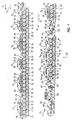
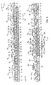
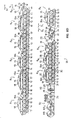
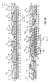
- FIGS 1 to 4 are schematic illustrations of the dry end of the paper machine which is shown from the forward dryer up to the machine reel-up.
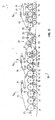
- Figure 5 is a schematic illustration of in part of the after-dryer of a paper machine.
- Figure 6A is schematic illustration of an exemplifying embodiment of the invention, in which figure the last dryer group in the after-dryer and the machine reel-up are shown.
- Figures 6B to 6E are schematic illustrations in which figures the dry end of a paper machine is shown from the forward dryer section to the machine reel-up.
- the paper web W is brought into the forward dryer section D1 from the press section onto the drying wire 15 of the first group R 0 with single-wire draw, to which wire the web is attached by the effect of the vacuum in the suction boxes 13.
- the forward dryer section includes 7 groups R 0 ...r 6 with single-wire draw, and the web W has closed draws over the group gaps between said groups.
- the machine direction i.e. the direction of progress of the of the web W is denoted with the arrow S.
- all the groups R 0 ...R N with single-wire draw are so-called normal groups, in which the, for example, steam-heated smooth-faced drying cylinders 10 are placed in the upper horizontal row and the reversing suction cylinders 11 are placed in the lower horizontal row.
- Each normal group R 0 ...R N has a drying wire 15 of its own, which is guided by the guide rolls 18.
- the drying wires 15 press the web W to be dried on the drying cylinders 10 against the smooth heated faces of the cylinders, and on the reversing cylinders 11 the web W remains at the side of the outside curve on the outside face of the wire 15.
- the web W is kept reliably on the support of the wire 15 against the effect of centrifugal forces by the effect of the vacuum present on the grooved faces 12 of the reversing cylinders 11 or on the perforated mantle of an equivalent suction roll, whereby cross-direction shrinkage of the web W is also counteracted.
- suction cylinders 11 particularly favourably are used the suction cylinders which are marketed by the applicant with the trade mark "VAC-ROLL”TM and which have no inside suction boxes, and with respect to the details of the constructions of said suction cylinders reference is made to the applicant's FI Patent No. 83,680 (equivalent to US Pats. Nos. 5,022,163 and 5,172,491 ).
- a forward dryer D1 the support contact between the web W and the drying wire 15 is kept adequate also on the straight draws between the drying cylinders 10 and the reversing cylinders 11 by, at least on the runs from the drying cylinders 10 to the reversing cylinders 11, making use of blow-suction boxes 17, by means of which boxes formation of pressures induced by the wire 15 is also prevented in the closing wedge-shaped nip spaces between the wire 15 and the cylinder 11 mantles.
- Blow-suction boxes 17 are understood as blow boxes whose air blowing produces a vacuum, and said boxes 17 do not communicate with sources of vacuum.
- blow-suction boxes 17 which are marketed by the applicant with the trade mark "UNO RUN BLOW BOX”TM
- Blow-box solutions of other types, in themselves known, are also included in the scope of the overall concept of the present invention.
- blow boxes 16 are also employed in the gaps between the reversing cylinders 11, by means of which boxes 16 said gap spaces are air-conditioned and evaporation from the web W is promoted.
- the faces of the drying cylinders 10 are kept clean by doctors 14.
- suction zone should preferably be extended over an area wider than the turning sector of the drying wire 15 and the web, so that the suction effect and the free flow of air can be extended into said wedge spaces, for the purposes mentioned above.
- the dry end of a paper machine in accordance with the invention includes a finishing unit D2 placed after the forward dryer D1, which finishing unit includes a machine reel-up 50, for example a Pope-type reel-up.
- a machine reel that is being produced on-line by means of the reel-up 50 is denoted with the reference MR 0
- one complete machine reel is denoted with the reference MR.
- the web W is brought to the machine reel-up 50 through the calender 40 from an after-dryer 30, which is placed after the coating device 20 in the finishing section D 2 .
- the paper web W which has been dried to a dry solids content of k 2 ⁇ 96...99 %, is passed over paper guide rolls 25 and over a measurement beam 26, which is placed between said guide rolls 25 and which measures the property profiles of the paper, into a coating device 20, which is, for example, a coating device marketed by the applicant with the name Sym-SizerTM.
- the coating device 20 includes two coating rolls 21 and 22 placed one opposite to the other, and size feed devices 23 and 24 are placed in connection with both of said rolls so that the paper web W is coated from both sides in the coating nip NS between the rolls 21 and 22.
- the web W is partly moistened in the coating nip NS from both sides. Then, the web W, which was dried in the forward dryer D1 asymmetrically from the side of its bottom face W and which has a tendency of curling, is treated into such a state that its internal strains are partly relaxed or at least substantially reduced.
- the forward dryer section D 1 is exclusively composed of dryer groups R 0 ...R 6 with single-wire draw; in which the paper web W runs meandering from a drying cylinder 10 onto a reversing roll 11 and onto a drying cylinder 10 and so on.
- the dryer groups R 0 ...R 6 in connection with some of the drying cylinders 10 in the groups, upper impingement blow equipments 19 have been fitted in order to regulate the curling, by means of which impingement blow equipments 19 hot air is blown towards the web W, and evaporation takes place through the wire 15 thus regulating the curling.
- the after-dryer 30 in the finishing section D 2 is also exclusively composed of dryer groups R 21 ,R 22 ,R 23 with single-wire draw, in connection with which groups an option has been arranged for an impingement blow equipment 19A for possible requirement of additional regulation of curling.
- the curling is controlled by means of steam boxes 31.
- an infra dryer 32 has been fitted.
- one steam box 31 has been fitted before the web W is passed to the calender 40.
- Impingement drying can be used in the forward dryer section D 1 also for requirements of additional capacity, for example for increased running speed and for two-sided drying.
- the blowings from the impingement blow devices 19 also affect the regulation of curling so that ventilation is provided in the web area, in which case the evaporation is less one-sided.
- the wire 15 must be as open as possible, and when the web runs, for example, at a speed of 25 metres per second, the blow velocity of the blow air must be 25 to 150 metres per second, optimally about 100 metres per second.
- the blow angle of the nozzles of the impingement blow devices 19 is chosen optimally based on the wire properties that are used, on the running speed of the machine, and on other parameters.
- the blow air can be outdoor air or heated air, up to 400 °C, preferably of a temperature of 70...200 °C.
- Fig. 2 the forward dryer section D 1 is similar to that shown in Fig. 1 , but here the after-dryer 30 is also provided with impingement blow devices 19.
- a lower support belt 33 In connection with the last dryer group R 23 in the after-dryer 30 a lower support belt 33 has been arranged, by means of which belt evaporation of water out of the bottom face of the web W is prevented, whereby the curling is regulated.
- the lower support belt 33 is a tight belt, which prevents removal of moisture through the bottom face, in which case the moisture is removed from the opposite side of the web W; thus, since the belt 33 prevents evaporation from the bottom face, the web W is curled towards the bottom face. It is a further advantage of the support belt 33 that here the web runs between two belts 33,15, in which case the web W is supported particularly well.
- a support belt 33 When a support belt 33 is used, its guide rolls 33A are placed at a lower level, approximately at the same level as the bottom edges of the reversing cylinders, in which case the removal of broke is easy as the belt 33 operates as a broke conveyor at the same time.
- the support belt 33 is preferably provided with a drive of its own, in which case its tension can be regulated as required.
- the support belt 33 is preferably a dense wire, whose permeability is low, or a smooth-faced belt.
- the temperature of the belt 33 can be adjusted, it can be cooled and/or heated as required when the curling is controlled. In this connection it is also favourably possible to introduce moist air into the area between the belt 33 and the reversing cylinders 11, whereby the process can be made more efficient.
- the forward dryer section D 1 in Fig. 3 is similar to those shown in Figs. 1 and 2 , but here the last two dryer groups R 32 ,R 33 in the after-dryer 30 have been formed as dryer groups with twin-wire draw, by means of which groups, thus, the curling is regulated.
- the dryer cylinders 10A, 10B are fitted in two rows, and the cylinders in each row have a wire circulation 15A, 15B of their own guided by the guide rolls 18A,18B, and between the rows the web W has free unsupported draws.
- Impingement blow devices 19 have been fitted in the forward dryer section in connection with the drying cylinders 10 in the upper row in view of regulating the curling, increasing the capacity, and providing two-sided drying.
- impingement blow equipments 19 have been provided additionally in connection with the first dryer group R 21 in the after-dryer.
- the steam temperature in the cylinders 10 is rather low, in which case the impingement blow devices 19 also provide additional capacity for heating the web W.
- the impingement blow devices 19 It is a particular advantage of the impingement blow devices 19, that their temperatures can be regulated quickly, in which case, for example, change of the machine from one paper grade to another is quicker, whereby additional production is achieved.
- a larger ratio of diameter of drying cylinder to diameter of reversing roll (D syl /D tela in Fig. 5 ) is employed, compared with the forward dryer section D 1 , in which case a more uniform evaporation is provided at the top/bottom side, and thereby the curling can be controlled.
- the after-dryer 30 in the finishing section D 2 is composed of two dryer groups R 21 ,R 22 with single-wire draw. In connection with the reversing rolls 11 in the latter group R 22 , steam boxes 31 have also been arranged in order to control the curling.
- the after-dryer 30 as shown in Fig. 5 can be fitted in connection with the forward dryers D 1 illustrated in the figures described above.
- the drying cylinders 10 have preferably adjustable steam pressures, and, if necessary, it is possible to use impingement blow devices 19 also in connection with these drying cylinders 10 in order to increase the capacity.
- impingement blow devices 19 At the side of the reversing cylinders 11, if necessary, it is possible to provide additional moisture, for example, by bringing moist air from the forward dryer section D 1 , by using a water atomizing equipment, support belts, or equivalent arrangements that have been described above and will be described later.
- a what is called spreader bar 34 has been fitted also in connection with the web, by means of which bar 34 the longitudinal curling of the web W is worked mechanically.
- the spreader bar 34 is a profiling roll, for example of the spreader roll type, in which case, in order to work the longitudinal curling, by its means it is also easy to act upon the cross-direction curling by means of mechanical working.
- a spreader bar 34 can be fitted at either side of the web or at both sides.
- Fig. 6D comprises a forward dryer section D 1 with single-wire draw, in which options have been arranged for possible impingement blow devices 19A.
- the regulation of curling has been arranged by means of steam boxes 31 and a water spray device 35 fitted in connection with the last dryer group R 23 in the after-dryer 30.
- the after-dryer there are optional provisions for impingement blow equipments 19A.
- Fig. 6E which is substantially similar to Fig. 6D , in view of regulation of curling, the last two groups R 22 ,R 23 in the after-dryer 30 are provided with lower support belts 33, which prevent evaporation of water, and, moreover, in connection with the last dryer group, steam boxes 31 and a water spray device 35 have been fitted.
- the emphasis is in particular on the control of curling before the calender 40 while the web W is cool.
- a particularly efficient combination is achieved, because, the hotter the web W is, the less readily is the steam condensed, in which connection, when cooling cylinders are used, efficient condensation of the steam is obtained.
- the web W tends to be curled towards the side at which drying takes place last.
- the curling can be affected at different stages in different ways so as to obtain an optimal application.
- the exemplifying embodiment illustrated in Fig. 6A is optimal when both the forward dryer and the after-dryer D 1 ,30 are accomplished exclusively by means of dryer groups R 0 ...R 6 ,R 21 ...R 23 with single-wire draw and when the tendency of curling is controlled mainly by means of the last dryer group R 23 in the after-dryer 30.
- a steam with a content of energy is blown out of the steam boxes 31, the superheating degree of said steam being preferably low in order that a condensation of maximal efficiency could be achieved.
- the temperature of the steam is typically 2...10 °C above the dew point temperature. In such a case, a joint effect of moistening and thermal energy is achieved in the control of curling.
- the steam box 31 extends substantially across the entire width of the web, and it is, of course, fitted as adjustable and as profiling.
- the web W can be moistened so that, in the final end of the dryer section, the face(s) of one or several drying cylinders is/are moistened, for example, by means of a water atomizing device fitted preferably in connection with a doctor 14, and the water fed out of said atomizer is vaporized and enters efficiently into contact with the web by the effect of the pressure caused by the wire.
- a water atomizing device fitted preferably in connection with a doctor 14
- the water fed out of said atomizer is vaporized and enters efficiently into contact with the web by the effect of the pressure caused by the wire.
- the patent FI 70,275 related to the present invention instructs to control the temperature of the drying wire so that the drying efficiency can be affected. Similarly, by means of the temperature of the drying wire it is possible to control the unequalsidedness of drying. According to the present invention, in the after-dryer there are devices by whose means the temperature of the drying wire or wires and, thereby, the curling are affected.
- the wire can be heated, for example, by means of a steam box. For cooling, it is possible to use, for example, the methods and devices known from said FI Patent 70,275 .
- the curling can also be controlled by adjusting the humidity and temperature of the air blown through UNORUNTM blow boxes.
- unequalsided evaporation and curling of the web can be affected by means of the humidity of the air in the hood surrounding the web from different sides.
Landscapes
- Paper (AREA)
- Drying Of Solid Materials (AREA)
Claims (24)
- Procédé de séchage de papier, lequel procédé comprend les étapes suivantes:a) on fait passer la bande de papier (W) à sécher de la section de presse dans une section de séchoir avant (D1), dans laquelle la bande de papier (W) est séchée du côté de sa face inférieure dans des groupes de séchoirs (R1... RN) qui appliquent une tension de toile unique normale, ladite section de séchoir avant (D1) comprenant exclusivement des groupes à toile unique (R1...RN) avec une tension de toile unique normale,b) on fait passer la bande de papier (W) de la section de séchoir avant (D1) dans une section de finition (D2), dans laquelle la bande de papier (W) est enrobée/gélatinée par le biais d'un équipement d'enrobage/de gélatinage (20), séchée dans une section post-séchoir (30), dans laquelle la bande de papier (W) est séchée dans au moins un groupe de séchoirs (R21) qui applique une tension de toile unique normale, suite à quoi la bande de papier (W) est calandrée dans une calandre (40) et transmise à une station d'enroulage (50), où la bande de papier (W) est enroulée dans une enrouleuse de machine (MR), etc) le roulage de la bande de papier est commandé par le biais d'éléments (19; 32; 33; 34; 35; 36; Dsyl, Dtela) et/ou par le biais d'assemblages et de combinaisons formé(e)s à partir desdits éléments et par le biais d'au moins une boîte à vapeur (31) au moins dans la zone de la section de finition (D2),caractérisé en ce que, dans le procédé, la condensation de la vapeur alimentée par ladite boîte à vapeur est intensifiée en refroidissant la bande avant ladite boîte à vapeur, en utilisant un cylindre de refroidissement avec une température ajustable.
- Procédé tel que revendiqué dans la revendication 1, caractérisé en ce que, dans le procédé, le roulage de la bande de papier (W) est affecté par le biais de dispositifs de soufflage par impact (19) placés dans la section de séchoir avant (D1) au-dessus d'un ou de cylindres (10) de séchage, dispositifs (19) par le biais desquels de l'air humide, chaud, de préférence, est soufflé vers la bande de papier (W).
- Procédé tel que revendiqué dans l'une quelconque des revendications 1 et 2, caractérisé en ce que dans le post-séchoir (30) le roulage de la bande de papier (W) est commandé par le biais de boîtes à vapeur (31), au moyen desquelles de la vapeur avec une teneur en énergie est soufflée sur la bande de papier (W) qui avance en relation avec les cylindres inverseurs (11) dans au moins un groupe de séchoirs (R21, R23) avec une tension de toile unique dans le post-séchoir (30).
- Procédé tel que revendiqué dans l'une quelconque des revendications 1 à 3, caractérisé en ce que, dans le procédé, le roulage de la bande de papier est commandé par le biais d'une toile ou d'une courroie de soutien inférieure (33) installée dans au moins un groupe de séchoirs (R21, R22, R23) dans le post-séchoir (30), toile/courroie de soutien par le biais de laquelle on empêche l'évaporation d'humidité vers le bas à partir de la bande de papier (W).
- Procédé tel que revendiqué dans la revendication 1, caractérisé en ce que, dans le procédé, dans une post-séchoir (30) avec au moins trois groupes de séchoirs, le roulage de la bande de papier (W) est commandé dans les deux derniers groupes de séchoirs dans le post-séchoir (30), lesquels groupes ont été agencés en tant que groupes de séchoirs (R23, R33) qui appliquent une tension de toile double, la bande de papier (W) étant séchée à la fois du côté de sa face supérieure et du côté de sa face inférieure.
- Procédé tel que revendiqué dans l'une quelconque des revendications 1 à 5, caractérisé en ce que dans le post-séchoir (30), le roulage de la bande de papier (W) est commandé par le biais d'un équipement de soufflage par impact (19) placé au-dessus d'un ou de cylindres (10) de séchage dans au moins un groupe de séchoirs (R21, R22, R23) avec une tension de toile unique normale dans le post-séchoir (30).
- Procédé tel que revendiqué dans l'une quelconque des revendications 1 à 6, caractérisé en ce que, dans le procédé, le roulage de la bande de papier (W) est commandé dans les groupes de séchoirs dans le post-séchoir (30) de sorte que la bande de papier (W) soit guidée sur de tels cylindres de séchage (10) et des rouleaux inverseurs (11) dont le rapport de diamètres (Dsyl ; Dtela) est plus grand en comparaison avec la section de séchoir avant (D1) pour qu'un séchage plus uniforme puisse être réalisé.
- Procédé tel que revendiqué dans l'une quelconque des revendications précédentes, caractérisé en ce que, dans le procédé, le roulage de la bande de papier est affecté en pulvérisant une brume d'eau en relation avec la bande de papier (W) par le biais d'un dispositif/de dispositifs d'atomisation à l'eau (35) dans le post-séchoir (30).
- Procédé tel que revendiqué dans l'une quelconque des revendications précédentes, caractérisé en ce que, dans le Procédé, le roulage de la bande de papier (W) est affecté par le biais d'un séchage à fond de la bande de papier (W) par le biais d'un séchoir à infrarouge (32) avant que la bande de papier (W) ne soit transférée dans la calandre (40).
- Procédé tel que revendiqué dans l'une quelconque des revendications précédentes, caractérisé en ce que, dans le procédé, le roulage de la bande de papier (W) est commandé en soufflant de l'air humide vers la bande de papier (W), air qui a été amené de préférence de la section de séchoir avant (D1), par l'intermédiaire de capots (36) placés en relation avec au moins un groupe de séchoirs (R21, R22, R23) dans le post-séchoir.
- Procédé tel que revendiqué dans l'une quelconque des revendications précédentes, caractérisé en ce que, dans le procédé, le roulage de la bande de papier (W) est commandé par le biais d'une barre déplisseuse (34) par l'intermédiaire de laquelle la bande de papier (W) est travaillée mécaniquement.
- Procédé tel que revendiqué dans l'une quelconque des revendications 1 à 3, caractérisé en ce que la section de séchoir avant est composée exclusivement de groupes normaux avec une tension de toile unique qui sont ouverts vers le fond, et/ou en ce que, dans le procédé, dans le post-séchoir (30), la bande de papier (W) est séchée essentiellement exclusivement par le biais de groupes de séchoirs (R21, R22, R23) avec une tension de toile unique normale.
- Train de séchage d'une machine à papier, qui comprend une section de séchoir avant (D1) et une section de finition (D2), laquelle section de finition (D2) comprend un équipement d'enrobage/de gélatinage (20), une post-séchoir (30), une calandre (40), et une station d'enroulage (50), et le train de séchage d'une machine à papier comprend en plus des éléments (19; 32; 33; 34; 35; 36; Dsyl, Dtela) et/ou des assemblages et des combinaisons formé(e)s à partir desdits éléments et au moins une boîte à vapeur (31) en vue de commander le roulage de la bande de papier (W) au moins dans la zone de la section de finition (D2), caractérisé en ce que ledit train de séchage d'une machine à papier comprend un cylindre de refroidissement à température ajustable pour réduire la température de la bande (W) avant ladite boîte à vapeur afin d'intensifier la condensation de la vapeur alimentée par ladite boîte à vapeur.
- Train de séchage d'une machine à papier tel que revendiqué dans la revendication 13 caractérisé en ce que le train de séchage comprend un équipement de soufflage par impact (19) installé en relation avec au moins un groupe de séchoirs au-dessus d'un ou de cylindres (10) de séchage dans la section de séchoir avant (D1) et/ou dans le post-séchoir (30).
- Train de séchage d'une machine à papier tel que revendiqué dans l'une quelconque des revendications 13 et 14, caractérisé en ce que le train de séchage comprend au moins une boîte à vapeur (31) installée dans le post-séchoir (30) afin de souffler de la vapeur vers la bande de papier (W) en relation avec les groupes (R21, R22, R23) avec une tension de toile unique dans le post-séchoir (30).
- Train de séchage d'une machine à papier tel que revendiqué dans l'une quelconque des revendications 13 à 15, caractérisée en ce que le train de séchage comprend au moins une toile ou une courroie de soutien (33) installée dans un groupe de séchoirs (R21, R22, R23) dans le post-séchoir (30) afin d'empêcher l'évaporation vers le bas d'humidité à partir de la bande de papier (W).
- Train de séchage d'une machine à papier tel que revendiqué dans l'une quelconque des revendications 13 à 16, caractérisé en ce que les deux derniers groupes de séchoirs dans le post-séchoir (30) sont des groupes de séchoirs (R23, R33) avec une tension de toile double.
- Train de séchage d'une machine à papier tel que revendiqué dans l'une quelconque des revendications 13 à 16, caractérisée en ce que dans le post-séchoir le rapport (Dsyl ; Dtela) du diamètre des cylindres de séchage est supérieur audit rapport dans la section de séchoir avant.
- Train de séchage d'une machine à papier tel que revendiqué dans l'une quelconque des revendications 13 à 18, caractérisée en ce que le train de séchage inclut un dispositif/des dispositifs de pulvérisation d'eau (35) dans le but de pulvériser une brume d'eau en relation avec la bande de papier (W) afin de commander le roulage.
- Train de séchage d'une machine à papier tel que revendiqué dans l'une quelconque des revendications 13 à 19, caractérisé en ce que le post-séchoir inclut un séchoir à infrarouge (32), qui est placé avant que la bande de papier ne soit transférée dans la calandre (40).
- Train de séchage d'une machine à papier tel que revendiqué dans l'une quelconque des revendications 13 à 19, caractérisé en ce que le train de séchage comprend des capots (36) installés en relation avec au moins un groupe de séchoirs dans le post-séchoir (30) en vue due souffler de l'air humide amené de la section de séchoir avant (D1) vers la bande de papier.
- Train de séchage d'une machine à papier tel que revendiqué dans l'une quelconque des revendications 13 à 21, caractérisé en ce que dans le post-séchoir une barre déplisseuse (34) est installée pour travailler la bande de papier mécaniquement et pour commander le roulage de la bande de papier.
- Train de séchage d'une machine à papier tel que revendiqué dans l'une quelconque des revendications 13 à 16 ou 18 à 22, caractérisé en ce que le post-séchoir (30) comprend exclusivement des groupes de séchoirs R21, R22, R23) avec une tension de toile unique normale.
- Procédé tel que revendiqué dans l'une quelconque des revendications 1 à 12 ou un Train de séchage d'une machine à papier tel que revendiqué dans l'une quelconque des revendications 13 à 23, caractérisé en ce que ladite section de séchoir et des dispositifs auxiliaires sont commandés sur la base de mesures en ligne ou hors ligne du roulage et d'une qualité en vue d'accomplir une qualité globale finale optimale.
Applications Claiming Priority (3)
| Application Number | Priority Date | Filing Date | Title |
|---|---|---|---|
| FI964830 | 1996-12-03 | ||
| FI964830A FI105935B (fi) | 1996-12-03 | 1996-12-03 | Menetelmä paperin kuivaamiseksi sekä paperikoneen kuivapää |
| PCT/FI1997/000745 WO1998027273A1 (fr) | 1996-12-03 | 1997-12-02 | Procede de sechage et du papier et section seche d'une machine a papier |
Publications (3)
| Publication Number | Publication Date |
|---|---|
| EP0943034A1 EP0943034A1 (fr) | 1999-09-22 |
| EP0943034B1 EP0943034B1 (fr) | 2002-10-23 |
| EP0943034B2 true EP0943034B2 (fr) | 2008-12-03 |
Family
ID=8547198
Family Applications (1)
| Application Number | Title | Priority Date | Filing Date |
|---|---|---|---|
| EP97946772A Expired - Lifetime EP0943034B2 (fr) | 1996-12-03 | 1997-12-02 | Procede de sechage du papier section seche d'une machine a papier |
Country Status (11)
| Country | Link |
|---|---|
| EP (1) | EP0943034B2 (fr) |
| JP (1) | JP3650131B2 (fr) |
| KR (1) | KR100391045B1 (fr) |
| CN (1) | CN1096529C (fr) |
| AT (1) | ATE226660T1 (fr) |
| AU (1) | AU5189798A (fr) |
| BR (1) | BR9713820A (fr) |
| CA (1) | CA2274228C (fr) |
| DE (1) | DE69716634T3 (fr) |
| FI (1) | FI105935B (fr) |
| WO (1) | WO1998027273A1 (fr) |
Families Citing this family (26)
| Publication number | Priority date | Publication date | Assignee | Title |
|---|---|---|---|---|
| US5983523A (en) * | 1997-03-27 | 1999-11-16 | Valmet Corporation | Method for controlling curl of paper in a dryer section of a paper machine and a paper or board machine |
| FI103999B1 (fi) * | 1997-04-22 | 1999-10-29 | Valmet Corp | Kuivatusyksikkö ja niitä soveltava kuivatusosa |
| US6038789A (en) * | 1997-05-15 | 2000-03-21 | Valmet Corporation | Method for controlling the curl of paper and a paper or board machine line that applies the method |
| US5992040A (en) * | 1998-02-11 | 1999-11-30 | Beloit Technologies, Inc. | Drying section apparatus |
| EP1125020B1 (fr) | 1998-08-04 | 2004-11-17 | Metso Paper, Inc. | Procede et dispositif de traitement de bandes de papier ou de carton |
| FI106269B (fi) | 1999-05-10 | 2000-12-29 | Valmet Corp | Päällepuhallussovitelma ja -menetelmä käsiteltävän paperi- tai kartonkirainan käyristymistaipumuksen kompensoimiseksi sekä paperi- tai kartonkikone |
| FI991096A7 (fi) * | 1999-05-12 | 2000-11-13 | Valmet Corp | Menetelmä paperin, erityisesti hienopaperin, valmistamiseksi ja paperi konelinja erityisesti hienopaperin valmistamista varten |
| FI121674B (fi) * | 2003-01-09 | 2011-02-28 | Metso Paper Inc | Menetelmä ja sovitelma liikkuvan paperi- tai kartonkirainan kostuttamiseksi |
| DE10325572A1 (de) * | 2003-06-05 | 2004-12-23 | Voith Paper Patent Gmbh | Vorrichtung und Verfahren zur Herstellung und/oder Behandlung einer Faserstoffbahn |
| DE10347953A1 (de) * | 2003-10-15 | 2005-05-19 | Voith Paper Patent Gmbh | Bahnbefeuchtung |
| DE102004017807A1 (de) * | 2004-04-13 | 2005-10-27 | Voith Paper Patent Gmbh | Trockenanordnung |
| JP4651314B2 (ja) * | 2004-06-15 | 2011-03-16 | レンゴー株式会社 | 紙・板紙の表面平滑処理装置 |
| DE102006049078A1 (de) * | 2006-10-13 | 2008-04-17 | Voith Patent Gmbh | Vorrichtung und Verfahren zur Herstellung einer Faserstoffbahn |
| DE102006049025A1 (de) * | 2006-10-13 | 2008-04-17 | Voith Patent Gmbh | Vorrichtung und Verfahren zur Herstellung einer Faserstoffbahn |
| DE102006049026A1 (de) * | 2006-10-13 | 2008-04-17 | Voith Patent Gmbh | Vorrichtung und Verfahren zur Herstellung einer Faserstoffbahn |
| DE102008000133A1 (de) * | 2008-01-23 | 2009-07-30 | Voith Patent Gmbh | Trockenpartie |
| DE202008005359U1 (de) * | 2008-04-17 | 2008-07-10 | Metso Paper, Inc. | Anordnung zur Einstellung der Krümmung der Papier-/Kartonbahn für ein wärmeempflindliches Produkt |
| KR101016727B1 (ko) * | 2008-07-30 | 2011-02-25 | 솔거특수지(주) | 전자소재 제조공정용 캐리어 용지의 제조방법 및 이를 위한장치와 그에 따라 제조된 캐리어 용지 |
| FI125147B (fi) * | 2011-08-31 | 2015-06-15 | Valmet Technologies Inc | Järjestelmä ja menetelmä paperin tai kartongin valmistamiseksi |
| CN102888777A (zh) * | 2012-10-23 | 2013-01-23 | 河南江河纸业股份有限公司 | 高速纸机干燥部 |
| EP2765237B1 (fr) | 2013-02-06 | 2016-11-23 | Valmet Technologies, Inc. | Procédé de production d'une bande de fibres et ligne de fabrication d'une bande de fibres |
| FR3022564B1 (fr) * | 2014-06-18 | 2017-06-30 | Allimand | Procede de sechage d'une bande de papier a cigarettes et papier a cigarettes ainsi obtenu |
| WO2018171959A1 (fr) * | 2017-03-21 | 2018-09-27 | Voith Patent Gmbh | Traitement de bande |
| DE102018119383A1 (de) * | 2018-08-09 | 2020-02-13 | Voith Patent Gmbh | Maschine und Verfahren zur Herstellung einer Wellpappenrohpapierbahn |
| CN112127200A (zh) * | 2020-09-30 | 2020-12-25 | 湖北中烟工业有限责任公司 | 一种饱和蒸汽加湿内衬纸的加湿系统 |
| CN114622434A (zh) * | 2022-04-18 | 2022-06-14 | 广东理文造纸有限公司 | 一种热缸控温涂布装置及其控温方法 |
Citations (4)
| Publication number | Priority date | Publication date | Assignee | Title |
|---|---|---|---|---|
| US3948721A (en) † | 1974-09-03 | 1976-04-06 | Winheim Karl H | Method and apparatus for wetting the web in paper making machines |
| EP0245250A1 (fr) † | 1985-11-06 | 1987-11-19 | Scott Paper Co | Procede de finissage de papier faisant appel au moulage thermique des couches inferieures. |
| DE4112537A1 (de) † | 1991-04-17 | 1992-10-22 | Escher Wyss Gmbh | Verfahren und vorrichtung zur glaetteerzeugung |
| EP0617165A1 (fr) † | 1993-03-08 | 1994-09-28 | Valmet Paper Machinery Inc. | Procédé de calandrage d'une bande de papier et calandre utilisant le procédé |
Family Cites Families (6)
| Publication number | Priority date | Publication date | Assignee | Title |
|---|---|---|---|---|
| FI91900C (fi) * | 1990-12-17 | 1994-08-25 | Valmet Paper Machinery Inc | Menetelmä paperikoneen kuivatusosalla paperin käyristymistaipumuksen vähentämiseksi ja menetelmän toteuttamiseen tarkoitettu kuivatusosa |
| FI103820B1 (fi) * | 1993-11-30 | 1999-09-30 | Valmet Paper Machinery Inc | Menetelmät paperirainan kuivatuksessa sekä paperikoneen kuivatusosat |
| FI93876C (fi) * | 1994-03-25 | 1995-06-12 | Valmet Paper Machinery Inc | Paperikoneen kuivatusosa, jossa on yksiviiraviennillä varustettuja sylinteriryhmiä |
| DE4415581C2 (de) * | 1994-05-04 | 1995-12-07 | Voith Gmbh J M | Papier-Streichvorrichtung |
| FI98387C (fi) * | 1995-02-01 | 1997-06-10 | Valmet Corp | Menetelmä pintakäsiteltävän paperin, etenkin hienopaperin, valmistamiseksi sekä paperikoneen kuivapää |
| FI104276B (fi) * | 1995-04-12 | 1999-12-15 | Valmet Corp | Kuivatusosakonsepti ja menetelmä paperirainan/kartonkirainan kuivatuksessa |
-
1996
- 1996-12-03 FI FI964830A patent/FI105935B/fi active
-
1997
- 1997-12-02 CN CN97180247A patent/CN1096529C/zh not_active Expired - Fee Related
- 1997-12-02 BR BR9713820-7A patent/BR9713820A/pt not_active IP Right Cessation
- 1997-12-02 AU AU51897/98A patent/AU5189798A/en not_active Abandoned
- 1997-12-02 EP EP97946772A patent/EP0943034B2/fr not_active Expired - Lifetime
- 1997-12-02 WO PCT/FI1997/000745 patent/WO1998027273A1/fr not_active Ceased
- 1997-12-02 JP JP52708098A patent/JP3650131B2/ja not_active Expired - Fee Related
- 1997-12-02 CA CA002274228A patent/CA2274228C/fr not_active Expired - Fee Related
- 1997-12-02 AT AT97946772T patent/ATE226660T1/de active
- 1997-12-02 KR KR10-1999-7003902A patent/KR100391045B1/ko not_active Expired - Fee Related
- 1997-12-02 DE DE69716634T patent/DE69716634T3/de not_active Expired - Lifetime
Patent Citations (4)
| Publication number | Priority date | Publication date | Assignee | Title |
|---|---|---|---|---|
| US3948721A (en) † | 1974-09-03 | 1976-04-06 | Winheim Karl H | Method and apparatus for wetting the web in paper making machines |
| EP0245250A1 (fr) † | 1985-11-06 | 1987-11-19 | Scott Paper Co | Procede de finissage de papier faisant appel au moulage thermique des couches inferieures. |
| DE4112537A1 (de) † | 1991-04-17 | 1992-10-22 | Escher Wyss Gmbh | Verfahren und vorrichtung zur glaetteerzeugung |
| EP0617165A1 (fr) † | 1993-03-08 | 1994-09-28 | Valmet Paper Machinery Inc. | Procédé de calandrage d'une bande de papier et calandre utilisant le procédé |
Non-Patent Citations (4)
| Title |
|---|
| Inbetriebnahme-/Übergabeprotokoll(D14) † |
| Jackson and Gavelin: The role of nip temperature..., Svensk Papperstidn. 67, No. 20,Oct. 1964 † |
| Krenkel; Bernhard: Glättwerksuntersuchungen, Zusammenhänge zwischen Glättparametern und Messgrössen, Dissertation and der Fak. für Maschinenwesen und Elektrotech. Der TU Graz, Heidenheim, 28.10.1975, Seiten 43-46 † |
| Prospekt von Devron-Hercules in Bezug auf einen Kalander aus dem Jahre 1990 † |
Also Published As
| Publication number | Publication date |
|---|---|
| JP3650131B2 (ja) | 2005-05-18 |
| FI964830A7 (fi) | 1998-06-04 |
| CN1239527A (zh) | 1999-12-22 |
| KR100391045B1 (ko) | 2003-07-12 |
| KR20000053015A (ko) | 2000-08-25 |
| DE69716634T3 (de) | 2009-07-16 |
| CA2274228C (fr) | 2007-03-27 |
| AU5189798A (en) | 1998-07-15 |
| ATE226660T1 (de) | 2002-11-15 |
| FI105935B (fi) | 2000-10-31 |
| EP0943034B1 (fr) | 2002-10-23 |
| BR9713820A (pt) | 2000-03-14 |
| CA2274228A1 (fr) | 1998-06-25 |
| EP0943034A1 (fr) | 1999-09-22 |
| CN1096529C (zh) | 2002-12-18 |
| FI964830A0 (fi) | 1996-12-03 |
| WO1998027273A1 (fr) | 1998-06-25 |
| DE69716634T2 (de) | 2003-06-26 |
| JP2001505630A (ja) | 2001-04-24 |
| DE69716634D1 (de) | 2002-11-28 |
Similar Documents
| Publication | Publication Date | Title |
|---|---|---|
| US6001421A (en) | Method for drying paper and a dry end of a paper machine | |
| EP0943034B1 (fr) | Procede de sechage et du papier et section seche d'une machine a papier | |
| EP0916763B1 (fr) | Procédé de fabrication de papier à surfaces travaillées et partie sèche d'une machine à papier | |
| US5968590A (en) | Method for drying a surface-treated paper web in an after-dryer of a paper machine and after-dryer of a paper machine | |
| US5775001A (en) | Dryer sections of a paper machine | |
| US6038789A (en) | Method for controlling the curl of paper and a paper or board machine line that applies the method | |
| US5588223A (en) | Restrained paper dryer | |
| WO1999032714A1 (fr) | Procede et appareil de sechage d'une bande continue de papier | |
| US6061927A (en) | Method for controlling curl of paper in a dryer section of a paper machine | |
| US6523278B1 (en) | Dryer section | |
| EP1012383B1 (fr) | Procede pour empecher le gondolage du papier dans la secherie d'une machine a papier et d'une machine a papier ou a carton | |
| US6193840B1 (en) | Method for producing surface-treated paper | |
| WO1998012380A1 (fr) | Procede pour le sechage d'une bande de papier traitee en surface ou similaire dans un cylindre de post-sechage d'une machine a papier et cylindre de post-sechage pour la realisation de ce procede | |
| US20060118257A1 (en) | Method for control of the curl of paper in the treatment of surface-sized paper, and finishing section of a paper machine | |
| US6094838A (en) | Curl and profile correction with high velocity hoods | |
| US5925407A (en) | Method for drying a surface-treated paper web in an after-dryer of a paper machine and after-dryer of a paper machine | |
| EP1009876A1 (fr) | Procede de tuilage du papier et chaine de machines a papier ou carton utilisant ce procede | |
| US6280576B1 (en) | After-dryer in a paper machine | |
| WO2000000696A1 (fr) | Procede et appareil d'humidification de la bande de papier dans la zone de sechage | |
| WO1998004777A1 (fr) | Procede de sechage d'un papier avant son traitement de surface en particulier du papier fin, dans un sechoir de machine a fabriquer du papier et sechoir de ladite machine a fabriquer du papier permettant de mettre en oeuvre ledit procede |
Legal Events
| Date | Code | Title | Description |
|---|---|---|---|
| PUAI | Public reference made under article 153(3) epc to a published international application that has entered the european phase |
Free format text: ORIGINAL CODE: 0009012 |
|
| 17P | Request for examination filed |
Effective date: 19990504 |
|
| AK | Designated contracting states |
Kind code of ref document: A1 Designated state(s): AT DE ES FR GB IT PT SE |
|
| 17Q | First examination report despatched |
Effective date: 20010808 |
|
| RAP1 | Party data changed (applicant data changed or rights of an application transferred) |
Owner name: METSO PAPER, INC. |
|
| GRAG | Despatch of communication of intention to grant |
Free format text: ORIGINAL CODE: EPIDOS AGRA |
|
| GRAG | Despatch of communication of intention to grant |
Free format text: ORIGINAL CODE: EPIDOS AGRA |
|
| GRAH | Despatch of communication of intention to grant a patent |
Free format text: ORIGINAL CODE: EPIDOS IGRA |
|
| GRAH | Despatch of communication of intention to grant a patent |
Free format text: ORIGINAL CODE: EPIDOS IGRA |
|
| GRAA | (expected) grant |
Free format text: ORIGINAL CODE: 0009210 |
|
| AK | Designated contracting states |
Kind code of ref document: B1 Designated state(s): AT DE ES FR GB IT PT SE |
|
| PG25 | Lapsed in a contracting state [announced via postgrant information from national office to epo] |
Ref country code: FR Free format text: LAPSE BECAUSE OF FAILURE TO SUBMIT A TRANSLATION OF THE DESCRIPTION OR TO PAY THE FEE WITHIN THE PRESCRIBED TIME-LIMIT Effective date: 20021023 |
|
| REF | Corresponds to: |
Ref document number: 226660 Country of ref document: AT Date of ref document: 20021115 Kind code of ref document: T |
|
| REG | Reference to a national code |
Ref country code: GB Ref legal event code: FG4D |
|
| REF | Corresponds to: |
Ref document number: 69716634 Country of ref document: DE Date of ref document: 20021128 |
|
| PG25 | Lapsed in a contracting state [announced via postgrant information from national office to epo] |
Ref country code: PT Free format text: LAPSE BECAUSE OF FAILURE TO SUBMIT A TRANSLATION OF THE DESCRIPTION OR TO PAY THE FEE WITHIN THE PRESCRIBED TIME-LIMIT Effective date: 20030123 Ref country code: GB Free format text: LAPSE BECAUSE OF NON-PAYMENT OF DUE FEES Effective date: 20030123 |
|
| PG25 | Lapsed in a contracting state [announced via postgrant information from national office to epo] |
Ref country code: ES Free format text: LAPSE BECAUSE OF FAILURE TO SUBMIT A TRANSLATION OF THE DESCRIPTION OR TO PAY THE FEE WITHIN THE PRESCRIBED TIME-LIMIT Effective date: 20030429 |
|
| PLBQ | Unpublished change to opponent data |
Free format text: ORIGINAL CODE: EPIDOS OPPO |
|
| PLBI | Opposition filed |
Free format text: ORIGINAL CODE: 0009260 |
|
| EN | Fr: translation not filed | ||
| GBPC | Gb: european patent ceased through non-payment of renewal fee | ||
| PLAX | Notice of opposition and request to file observation + time limit sent |
Free format text: ORIGINAL CODE: EPIDOSNOBS2 |
|
| 26 | Opposition filed |
Opponent name: VOITH PAPER PATENT GMBH Effective date: 20030723 |
|
| PLAX | Notice of opposition and request to file observation + time limit sent |
Free format text: ORIGINAL CODE: EPIDOSNOBS2 |
|
| PLBB | Reply of patent proprietor to notice(s) of opposition received |
Free format text: ORIGINAL CODE: EPIDOSNOBS3 |
|
| APBP | Date of receipt of notice of appeal recorded |
Free format text: ORIGINAL CODE: EPIDOSNNOA2O |
|
| APAH | Appeal reference modified |
Free format text: ORIGINAL CODE: EPIDOSCREFNO |
|
| APBQ | Date of receipt of statement of grounds of appeal recorded |
Free format text: ORIGINAL CODE: EPIDOSNNOA3O |
|
| APAH | Appeal reference modified |
Free format text: ORIGINAL CODE: EPIDOSCREFNO |
|
| APBU | Appeal procedure closed |
Free format text: ORIGINAL CODE: EPIDOSNNOA9O |
|
| PGFP | Annual fee paid to national office [announced via postgrant information from national office to epo] |
Ref country code: IT Payment date: 20071221 Year of fee payment: 11 |
|
| PGFP | Annual fee paid to national office [announced via postgrant information from national office to epo] |
Ref country code: SE Payment date: 20071213 Year of fee payment: 11 |
|
| PUAH | Patent maintained in amended form |
Free format text: ORIGINAL CODE: 0009272 |
|
| STAA | Information on the status of an ep patent application or granted ep patent |
Free format text: STATUS: PATENT MAINTAINED AS AMENDED |
|
| 27A | Patent maintained in amended form |
Effective date: 20081203 |
|
| AK | Designated contracting states |
Kind code of ref document: B2 Designated state(s): AT DE ES FR GB IT PT SE |
|
| REG | Reference to a national code |
Ref country code: ES Ref legal event code: FD2A Effective date: 20021203 |
|
| PG25 | Lapsed in a contracting state [announced via postgrant information from national office to epo] |
Ref country code: SE Free format text: LAPSE BECAUSE OF NON-PAYMENT OF DUE FEES Effective date: 20081203 |
|
| PGFP | Annual fee paid to national office [announced via postgrant information from national office to epo] |
Ref country code: AT Payment date: 20121212 Year of fee payment: 16 |
|
| PG25 | Lapsed in a contracting state [announced via postgrant information from national office to epo] |
Ref country code: IT Free format text: LAPSE BECAUSE OF NON-PAYMENT OF DUE FEES Effective date: 20081202 |
|
| PGFP | Annual fee paid to national office [announced via postgrant information from national office to epo] |
Ref country code: DE Payment date: 20131220 Year of fee payment: 17 |
|
| REG | Reference to a national code |
Ref country code: AT Ref legal event code: MM01 Ref document number: 226660 Country of ref document: AT Kind code of ref document: T Effective date: 20131202 |
|
| PG25 | Lapsed in a contracting state [announced via postgrant information from national office to epo] |
Ref country code: AT Free format text: LAPSE BECAUSE OF NON-PAYMENT OF DUE FEES Effective date: 20131202 |
|
| REG | Reference to a national code |
Ref country code: DE Ref legal event code: R119 Ref document number: 69716634 Country of ref document: DE |
|
| PG25 | Lapsed in a contracting state [announced via postgrant information from national office to epo] |
Ref country code: DE Free format text: LAPSE BECAUSE OF NON-PAYMENT OF DUE FEES Effective date: 20150701 |