EP0943111B1 - Dispositif de couplage optique d'un laser a corps solide a une fibre optique et procede de production dudit dispositif - Google Patents
Dispositif de couplage optique d'un laser a corps solide a une fibre optique et procede de production dudit dispositif Download PDFInfo
- Publication number
- EP0943111B1 EP0943111B1 EP97951967A EP97951967A EP0943111B1 EP 0943111 B1 EP0943111 B1 EP 0943111B1 EP 97951967 A EP97951967 A EP 97951967A EP 97951967 A EP97951967 A EP 97951967A EP 0943111 B1 EP0943111 B1 EP 0943111B1
- Authority
- EP
- European Patent Office
- Prior art keywords
- solid
- state laser
- optical
- lens
- optical system
- Prior art date
- Legal status (The legal status is an assumption and is not a legal conclusion. Google has not performed a legal analysis and makes no representation as to the accuracy of the status listed.)
- Expired - Lifetime
Links
- 230000003287 optical effect Effects 0.000 title claims abstract description 33
- 238000000034 method Methods 0.000 title claims description 20
- 230000008569 process Effects 0.000 title claims description 11
- 230000008878 coupling Effects 0.000 title abstract description 8
- 238000010168 coupling process Methods 0.000 title abstract description 8
- 238000005859 coupling reaction Methods 0.000 title abstract description 8
- 238000004519 manufacturing process Methods 0.000 title description 7
- 238000001459 lithography Methods 0.000 claims description 6
- 238000000609 electron-beam lithography Methods 0.000 claims description 4
- 239000004922 lacquer Substances 0.000 claims description 4
- 239000000654 additive Substances 0.000 claims description 3
- 230000000996 additive effect Effects 0.000 claims description 3
- 239000013307 optical fiber Substances 0.000 abstract description 10
- 239000000835 fiber Substances 0.000 description 6
- 238000010894 electron beam technology Methods 0.000 description 4
- 239000003973 paint Substances 0.000 description 3
- 229920000642 polymer Polymers 0.000 description 3
- VYPSYNLAJGMNEJ-UHFFFAOYSA-N Silicium dioxide Chemical compound O=[Si]=O VYPSYNLAJGMNEJ-UHFFFAOYSA-N 0.000 description 2
- 238000000313 electron-beam-induced deposition Methods 0.000 description 2
- 238000005516 engineering process Methods 0.000 description 2
- 239000000463 material Substances 0.000 description 2
- 238000004377 microelectronic Methods 0.000 description 2
- 210000001747 pupil Anatomy 0.000 description 2
- 239000004065 semiconductor Substances 0.000 description 2
- 229910052814 silicon oxide Inorganic materials 0.000 description 2
- 125000006850 spacer group Chemical group 0.000 description 2
- 230000006978 adaptation Effects 0.000 description 1
- 230000008901 benefit Effects 0.000 description 1
- 238000007796 conventional method Methods 0.000 description 1
- 238000004132 cross linking Methods 0.000 description 1
- 238000005137 deposition process Methods 0.000 description 1
- 238000011161 development Methods 0.000 description 1
- 238000009826 distribution Methods 0.000 description 1
- 238000001312 dry etching Methods 0.000 description 1
- 238000005530 etching Methods 0.000 description 1
- 238000011156 evaluation Methods 0.000 description 1
- 239000002657 fibrous material Substances 0.000 description 1
- 230000004907 flux Effects 0.000 description 1
- 238000003780 insertion Methods 0.000 description 1
- 230000037431 insertion Effects 0.000 description 1
- 238000010884 ion-beam technique Methods 0.000 description 1
- 238000000608 laser ablation Methods 0.000 description 1
- 238000006116 polymerization reaction Methods 0.000 description 1
- 239000002243 precursor Substances 0.000 description 1
- 238000012545 processing Methods 0.000 description 1
- 230000009467 reduction Effects 0.000 description 1
- 238000004621 scanning probe microscopy Methods 0.000 description 1
- 239000000126 substance Substances 0.000 description 1
- 238000007740 vapor deposition Methods 0.000 description 1
Images

Classifications
-
- G—PHYSICS
- G02—OPTICS
- G02B—OPTICAL ELEMENTS, SYSTEMS OR APPARATUS
- G02B6/00—Light guides; Structural details of arrangements comprising light guides and other optical elements, e.g. couplings
- G02B6/24—Coupling light guides
- G02B6/42—Coupling light guides with opto-electronic elements
- G02B6/4201—Packages, e.g. shape, construction, internal or external details
- G02B6/4204—Packages, e.g. shape, construction, internal or external details the coupling comprising intermediate optical elements, e.g. lenses, holograms
- G02B6/4206—Optical features
-
- G—PHYSICS
- G02—OPTICS
- G02B—OPTICAL ELEMENTS, SYSTEMS OR APPARATUS
- G02B6/00—Light guides; Structural details of arrangements comprising light guides and other optical elements, e.g. couplings
- G02B6/24—Coupling light guides
- G02B6/42—Coupling light guides with opto-electronic elements
- G02B6/4296—Coupling light guides with opto-electronic elements coupling with sources of high radiant energy, e.g. high power lasers, high temperature light sources
-
- G—PHYSICS
- G02—OPTICS
- G02B—OPTICAL ELEMENTS, SYSTEMS OR APPARATUS
- G02B6/00—Light guides; Structural details of arrangements comprising light guides and other optical elements, e.g. couplings
- G02B6/24—Coupling light guides
- G02B6/26—Optical coupling means
- G02B6/32—Optical coupling means having lens focusing means positioned between opposed fibre ends
Definitions
- the invention relates to an optical arrangement consisting of a solid-state laser, an optical fiber and one optical system, the between the exit surface of the Solid-state laser and the entrance surface of the Optical fiber arranged in the optical system Main sections of the solid-state laser different Apertures in substantially the same apertures on the Formed entrance surface of the optical fiber, and a Process for their production.
- the object of the present invention is a device for coupling a solid-state laser with a Propose fiber optics, which is largely lossless coupling and adaptation of the wave fields in the direction of both main cuts and with the required accuracy can be produced.
- optical system from one on the exit surface constructed lens system with different Magnification in the main sections and one on the Entry surface constructed further lens and is the optical system is designed to adapt the To reach wave fields in the direction of both main cuts.
- the device according to the invention has the advantage that the Lenses each with very high accuracy on the exit or. Entry surface can be applied. A Adjustment is then only between the laser axis and the axis of the optical fiber is required. You can both the lens system and the further lens in advantageously produced by known processes become.
- the device according to the invention there is anamorphic lens on the entrance surface is not excluded, but it is preferably provided that the other lens is spherical. Furthermore, the Invention different configurations possible, for example that on the exit surface of the laser built-up lens system one Fresnel lens or two crossed cylindrical partial lenses is formed, wherein at least one of the partial lenses is designed as a Fresnel lens is.
- the advantageous embodiment of the invention Device can also be designed such that between the lens system and the exit surface Spacer layer corresponding to that in the direction of Larger aperture required magnification is provided.
- the exit pupils of the laser virtually into a round Source image are shown. This can make a small one Distance between the lenses or the exit surface and the Entry area with relatively large focal lengths of the lenses to get voted. The large focal lengths of the lenses are again cheaper for the production by microtechnical Method.
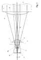
- An anamorphic plano-convex lens 2 with the focal points F y and -F y is located in a plane 1.
- the light exit surface of a solid-state laser, which is otherwise not shown, lies in level 3.
- the source image is 4, with a virtual enlarged image of the source image being 5.
- optical fiber consists of an optically active core 6 and a jacket 7.
- a spherical lens 9 applied, which the virtual Figure 5 real in the Core 6 is shown.
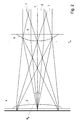
- Fig. 2 shows the same embodiment in the xz section.
- a lens with a long focal length or Fresnel lens (in the case of the exemplary embodiment according to FIG. 3) with a long focal length is applied to the exit surface of the laser, with which the light with a small aperture a 0 is focused onto the lens 9.
Landscapes
- Physics & Mathematics (AREA)
- General Physics & Mathematics (AREA)
- Optics & Photonics (AREA)
- Optical Couplings Of Light Guides (AREA)
- Exposure And Positioning Against Photoresist Photosensitive Materials (AREA)
- Optical Integrated Circuits (AREA)
- Lasers (AREA)
- Eyeglasses (AREA)
- Laser Surgery Devices (AREA)
Claims (9)
- Dispositif optique composé d'un laser solide, d'un guide d'onde optique et d'un système optique, dans lequel le système optique placé entre la face de sortie du laser solide et la face d'entrée du guide d'onde optique convertit différentes ouvertures dans les sections principales du laser solide en ouvertures globalement identiques sur la face d'entrée du guide d'onde optique, caractérisé en ce que le système optique est constitué d'un système de lentilles (2) monté sur la face de sortie (3) avec une échelle de reproduction différente dans les sections principales et une lentille supplémentaire (9) montée sur la face d'entrée (8), le système optique étant aménagé de manière à permettre une adaptation des champs d'ondes en direction des deux sections principales.
- Dispositif selon la revendication 1 caractérisé en ce que la lentille supplémentaire (9) est sphérique.
- Dispositif selon la revendication 1 ou 2 caractérisé en ce que le système de lentilles est monté en lentille de Fresnel (21).
- Dispositif selon la revendication 1 ou 2 caractérisé en ce que le système de lentilles est constitué de deux sous-lentilles cylindriques croisées et qu'au moins une des sous-lentilles est montée en lentille de Fresnel.
- Dispositif selon l'une des revendications 1 à 5 caractérisé en ce que, entre le système de lentilles (2) et la face de sortie (39), il est prévu une couche-entretoise adaptée à l'agrandissement nécessaire dans le sens de la grande ouverture.
- Procédé de fabrication d'un dispositif optique composé d'un laser solide, d'un guide d'onde optique et d'un système optique, dans lequel le système optique placé entre la face de sortie du laser solide et la face d'entrée du guide d'onde optique convertit différentes ouvertures dans les sections principales du laser solide en ouvertures globalement identiques sur la face d'entrée du guide d'onde optique et le système optique est constitué d'un système de lentilles monté sur la face de sortie avec une échelle de reproduction différente dans les sections principales et une lentille supplémentaire montée sur la face d'entrée, caractérisé en ce qu'au moins les lentilles sont fabriquées en laque sèche.
- Procédé selon la revendication 6 caractérisé en ce que des couches-entretoises et des couches antireflet sont de plus fabriquées en laque sèche.
- Procédé de fabrication d'un dispositif optique composé d'un laser solide, d'un guide d'onde optique et d'un système optique, dans lequel le système optique placé entre la face de sortie du laser solide et la face d'entrée du guide d'onde optique convertit différentes ouvertures dans les sections principales du laser solide en ouvertures globalement identiques sur la face d'entrée du guide d'onde optique et le système optique est constitué d'un système de lentilles monté sur la face de sortie avec une échelle de reproduction différente dans les sections principales et une lentille supplémentaire montée sur la face d'entrée, caractérisé en ce qu'au moins les lentilles sont fabriquées par lithographie additive, en particulier par lithographie par faisceau d'électrons.
- Procédé selon la revendication 8 caractérisé en ce que des couches-entretoises et des couches antireflet sont de plus fabriquées selon lithographie additive.
Applications Claiming Priority (3)
| Application Number | Priority Date | Filing Date | Title |
|---|---|---|---|
| DE19650696A DE19650696A1 (de) | 1996-12-06 | 1996-12-06 | Vorrichtung zur optischen Kopplung eines Festkörperlasers mit einem Lichtwellenleiter und Verfahren zu deren Herstellung |
| DE19650696 | 1996-12-06 | ||
| PCT/EP1997/006566 WO1998025170A1 (fr) | 1996-12-06 | 1997-11-25 | Dispositif de couplage optique d'un laser a corps solide a une fibre optique et procede de production dudit dispositif |
Publications (2)
| Publication Number | Publication Date |
|---|---|
| EP0943111A1 EP0943111A1 (fr) | 1999-09-22 |
| EP0943111B1 true EP0943111B1 (fr) | 2001-10-04 |
Family
ID=7813865
Family Applications (1)
| Application Number | Title | Priority Date | Filing Date |
|---|---|---|---|
| EP97951967A Expired - Lifetime EP0943111B1 (fr) | 1996-12-06 | 1997-11-25 | Dispositif de couplage optique d'un laser a corps solide a une fibre optique et procede de production dudit dispositif |
Country Status (10)
| Country | Link |
|---|---|
| US (1) | US6370298B2 (fr) |
| EP (1) | EP0943111B1 (fr) |
| JP (1) | JP2001504950A (fr) |
| CN (1) | CN1144073C (fr) |
| AT (1) | ATE206528T1 (fr) |
| CA (1) | CA2273930C (fr) |
| DE (2) | DE19650696A1 (fr) |
| ES (1) | ES2165633T3 (fr) |
| NO (1) | NO319919B1 (fr) |
| WO (1) | WO1998025170A1 (fr) |
Families Citing this family (10)
| Publication number | Priority date | Publication date | Assignee | Title |
|---|---|---|---|---|
| WO2002091048A1 (fr) * | 2001-04-20 | 2002-11-14 | Huawei Technologies Co., Ltd. | Dispositif de connexion d'une source lumineuse de pompage d'un amplificateur a fibre a plusieurs etages a dopage er |
| CN100470198C (zh) * | 2003-02-28 | 2009-03-18 | 株式会社日本耐美得 | 步行者导航设备 |
| US20060056762A1 (en) * | 2003-07-02 | 2006-03-16 | Honeywell International Inc. | Lens optical coupler |
| US7324723B2 (en) * | 2003-10-06 | 2008-01-29 | Mitsui Chemicals, Inc. | Optical waveguide having specular surface formed by laser beam machining |
| JP4488287B2 (ja) * | 2003-11-21 | 2010-06-23 | フジノン株式会社 | ビーム集光用レンズ |
| US7520062B2 (en) * | 2005-12-06 | 2009-04-21 | Robert Bosch Tool Corporation | Light-plane projecting apparatus and lens |
| GB201011058D0 (en) | 2010-07-01 | 2010-08-18 | Oclaro Technology Plc | Fibre optical coupling |
| JP2012168240A (ja) * | 2011-02-10 | 2012-09-06 | Sumitomo Electric Device Innovations Inc | 光モジュール |
| TW201516533A (zh) * | 2013-10-21 | 2015-05-01 | Hon Hai Prec Ind Co Ltd | 背光模組 |
| CN112424669B (zh) * | 2018-07-24 | 2022-11-29 | 株式会社尼康 | 目镜光学系统以及头戴式显示器 |
Family Cites Families (14)
| Publication number | Priority date | Publication date | Assignee | Title |
|---|---|---|---|---|
| JPS616889A (ja) * | 1984-06-21 | 1986-01-13 | Matsushita Electric Ind Co Ltd | 半導体発光素子およびその製造方法 |
| NL8600844A (nl) * | 1986-04-02 | 1987-11-02 | Tno | Optisch vezel-strookgeleidersamenstel met lichtkoppeling tussen een vezel en een op een substraat aangebrachte planaire strookgeleider. |
| JPS63100790A (ja) * | 1986-10-17 | 1988-05-02 | Nec Corp | 半導体レ−ザモジユ−ル |
| GB2220501A (en) | 1988-07-06 | 1990-01-10 | Plessey Co Plc | Coupling waveguides using transverse cylindrical lenses |
| DE3919484A1 (de) | 1989-04-15 | 1990-10-18 | Rodenstock Optik G | Optisches system zur aenderung der form des strahlquerschnittes von lichtbuendeln |
| US5081639A (en) | 1990-10-01 | 1992-01-14 | The United States Of America As Represented By The United States Department Of Energy | Laser diode assembly including a cylindrical lens |
| CH682698A5 (de) | 1990-11-01 | 1993-10-29 | Fisba Optik Ag Bystronic Laser | Verfahren, bei dem mehrere, in einer oder mehreren Reihen angeordnete Strahlungsquellen abgebildet werden und Vorrichtung hierzu. |
| US5181224A (en) | 1991-05-10 | 1993-01-19 | University Of California | Microoptic lenses |
| US5140608A (en) | 1991-05-29 | 1992-08-18 | Optrotech Ltd, Israel Company | Optical system for focusing a light beam on to an image plane |
| US5455879A (en) * | 1994-06-22 | 1995-10-03 | Corning Incorporated | Anamorphic microlens for coupling optical fibers to elliptical light beams |
| EP0706070A3 (fr) * | 1994-10-04 | 1997-04-02 | Siemens Ag | Procédé de gravure sèche d'un substrat semi-conducteur |
| US5790576A (en) * | 1996-06-26 | 1998-08-04 | Sdl, Inc. | High brightness laser diode source |
| US5946140A (en) * | 1998-03-06 | 1999-08-31 | Lucent Technologies Inc. | Fiber lens for use with a confocal lens system |
| US6026206A (en) * | 1998-03-06 | 2000-02-15 | Lucent Technologies, Inc. | Optical coupler using anamorphic microlens |
-
1996
- 1996-12-06 DE DE19650696A patent/DE19650696A1/de not_active Withdrawn
-
1997
- 1997-11-25 CN CNB971803935A patent/CN1144073C/zh not_active Expired - Lifetime
- 1997-11-25 JP JP52514398A patent/JP2001504950A/ja not_active Ceased
- 1997-11-25 US US09/319,510 patent/US6370298B2/en not_active Expired - Lifetime
- 1997-11-25 EP EP97951967A patent/EP0943111B1/fr not_active Expired - Lifetime
- 1997-11-25 CA CA002273930A patent/CA2273930C/fr not_active Expired - Lifetime
- 1997-11-25 ES ES97951967T patent/ES2165633T3/es not_active Expired - Lifetime
- 1997-11-25 DE DE59704815T patent/DE59704815D1/de not_active Expired - Lifetime
- 1997-11-25 AT AT97951967T patent/ATE206528T1/de active
- 1997-11-25 WO PCT/EP1997/006566 patent/WO1998025170A1/fr not_active Ceased
-
1999
- 1999-06-03 NO NO19992696A patent/NO319919B1/no not_active IP Right Cessation
Also Published As
| Publication number | Publication date |
|---|---|
| CN1240031A (zh) | 1999-12-29 |
| NO319919B1 (no) | 2005-10-03 |
| NO992696L (no) | 1999-07-27 |
| WO1998025170A1 (fr) | 1998-06-11 |
| JP2001504950A (ja) | 2001-04-10 |
| US6370298B2 (en) | 2002-04-09 |
| US20020009259A1 (en) | 2002-01-24 |
| DE19650696A1 (de) | 1998-06-10 |
| ATE206528T1 (de) | 2001-10-15 |
| CA2273930C (fr) | 2007-01-16 |
| ES2165633T3 (es) | 2002-03-16 |
| CA2273930A1 (fr) | 1998-06-11 |
| DE59704815D1 (de) | 2001-11-08 |
| CN1144073C (zh) | 2004-03-31 |
| EP0943111A1 (fr) | 1999-09-22 |
| NO992696D0 (no) | 1999-06-03 |
Similar Documents
| Publication | Publication Date | Title |
|---|---|---|
| DE3101378C2 (de) | Optik zur Ankopplung eines faseroptischen Lichtwellenleiters | |
| DE69127680T2 (de) | Verfahren zur Herstellung einer länglichen integrierten optischen Vorrichtung mit wenigstens einem seitlich begrenzten Wellenleiter darin | |
| EP0943111B1 (fr) | Dispositif de couplage optique d'un laser a corps solide a une fibre optique et procede de production dudit dispositif | |
| EP0560043A2 (fr) | Méthode de fabrication d'éléments pour des réseaux de guide d'ondes et éléments fabriqués utilisant cette méthode | |
| EP0583679A1 (fr) | Dispositif pour transformer une onde optique avec une coupe transversale relativement petite en une onde optique avec une coupe transversale plus large | |
| DE69413373T2 (de) | Methode zur Herstellung von Faser-Tastspitzen unter Benutzung von strukturiertem reaktiven Ionenätzen | |
| DE2553685A1 (de) | Verfahren zur herstellung von optischen richtkopplern | |
| WO1997032229A1 (fr) | Procede de production de composants optiques avec guides d'ondes optiques accouples, et composants optiques produits selon ce procede | |
| EP0847329B1 (fr) | Procede de production de couches polymeres structurees en trois dimensions pour l'optique integre | |
| EP0564438A1 (fr) | Système de formation d'images par faisceau de particules notamment système d'imagerie en optique ionique | |
| EP0043475B1 (fr) | Procédé de fabrication d'un dispositif microoptique intégré pour application avec des fibres multimodes | |
| EP0509342B1 (fr) | Procédé de fabrication de structures en forme de coin | |
| DE2331497A1 (de) | Anordnung zum einkoppeln von laserstrahlen in optische fasern | |
| WO1995019637A1 (fr) | Systeme de reproduction par faisceaux de particules, notamment systeme de reproduction optique ionique | |
| EP0877965A1 (fr) | Procede de production de composants optiques et composant optique ainsi obtenu | |
| EP1588383B1 (fr) | Sonde pour un microscope optique a champ proche et prodede de production de ladite sonde | |
| DE19545721C2 (de) | Verfahren und Vorrichtung zum Herstellen und präzisen Positionieren von optischen Mikrokomponenten auf einer über einer optischen Einrichtung | |
| EP0398082A1 (fr) | Procédé de fabrication d'une lentille optique | |
| DE19923444C2 (de) | Verfahren zur Herstellung einer lichttransparenten Sondenspitze | |
| DE4412254A1 (de) | Optisches Koppelglied und Verfahren zu dessen Herstellung | |
| WO2004068502A2 (fr) | Sonde pour un microscope optique a champ proche a attenuation amelioree de la lumiere diffusee et procede de production de ladite sonde | |
| DE3228605C2 (fr) | ||
| DE4200396C1 (fr) | ||
| EP0744798A1 (fr) | Dispositif pour le couplage d'un laser | |
| DE19500598A1 (de) | Anordnung zum Ankoppeln einer Lichtleitfaser an einen Lichtwellenleiter und Verfahren zur Herstellung einer Koppelstelle |
Legal Events
| Date | Code | Title | Description |
|---|---|---|---|
| PUAI | Public reference made under article 153(3) epc to a published international application that has entered the european phase |
Free format text: ORIGINAL CODE: 0009012 |
|
| 17P | Request for examination filed |
Effective date: 19990706 |
|
| AK | Designated contracting states |
Kind code of ref document: A1 Designated state(s): AT BE CH DE DK ES FI FR GB GR IE IT LI LU MC NL PT SE |
|
| 17Q | First examination report despatched |
Effective date: 19990922 |
|
| GRAG | Despatch of communication of intention to grant |
Free format text: ORIGINAL CODE: EPIDOS AGRA |
|
| GRAG | Despatch of communication of intention to grant |
Free format text: ORIGINAL CODE: EPIDOS AGRA |
|
| GRAH | Despatch of communication of intention to grant a patent |
Free format text: ORIGINAL CODE: EPIDOS IGRA |
|
| GRAH | Despatch of communication of intention to grant a patent |
Free format text: ORIGINAL CODE: EPIDOS IGRA |
|
| GRAA | (expected) grant |
Free format text: ORIGINAL CODE: 0009210 |
|
| AK | Designated contracting states |
Kind code of ref document: B1 Designated state(s): AT BE CH DE DK ES FI FR GB GR IE IT LI LU MC NL PT SE |
|
| PG25 | Lapsed in a contracting state [announced via postgrant information from national office to epo] |
Ref country code: IE Free format text: LAPSE BECAUSE OF FAILURE TO SUBMIT A TRANSLATION OF THE DESCRIPTION OR TO PAY THE FEE WITHIN THE PRESCRIBED TIME-LIMIT Effective date: 20011004 |
|
| REF | Corresponds to: |
Ref document number: 206528 Country of ref document: AT Date of ref document: 20011015 Kind code of ref document: T |
|
| REG | Reference to a national code |
Ref country code: CH Ref legal event code: EP |
|
| REG | Reference to a national code |
Ref country code: CH Ref legal event code: NV Representative=s name: HUG INTERLIZENZ AG |
|
| REF | Corresponds to: |
Ref document number: 59704815 Country of ref document: DE Date of ref document: 20011108 |
|
| REG | Reference to a national code |
Ref country code: IE Ref legal event code: FG4D Free format text: GERMAN |
|
| PG25 | Lapsed in a contracting state [announced via postgrant information from national office to epo] |
Ref country code: MC Free format text: LAPSE BECAUSE OF NON-PAYMENT OF DUE FEES Effective date: 20011125 Ref country code: LU Free format text: LAPSE BECAUSE OF NON-PAYMENT OF DUE FEES Effective date: 20011125 |
|
| PG25 | Lapsed in a contracting state [announced via postgrant information from national office to epo] |
Ref country code: BE Free format text: LAPSE BECAUSE OF NON-PAYMENT OF DUE FEES Effective date: 20011130 |
|
| REG | Reference to a national code |
Ref country code: GB Ref legal event code: IF02 |
|
| PG25 | Lapsed in a contracting state [announced via postgrant information from national office to epo] |
Ref country code: PT Free format text: LAPSE BECAUSE OF FAILURE TO SUBMIT A TRANSLATION OF THE DESCRIPTION OR TO PAY THE FEE WITHIN THE PRESCRIBED TIME-LIMIT Effective date: 20020104 Ref country code: DK Free format text: LAPSE BECAUSE OF FAILURE TO SUBMIT A TRANSLATION OF THE DESCRIPTION OR TO PAY THE FEE WITHIN THE PRESCRIBED TIME-LIMIT Effective date: 20020104 |
|
| PG25 | Lapsed in a contracting state [announced via postgrant information from national office to epo] |
Ref country code: GR Free format text: LAPSE BECAUSE OF FAILURE TO SUBMIT A TRANSLATION OF THE DESCRIPTION OR TO PAY THE FEE WITHIN THE PRESCRIBED TIME-LIMIT Effective date: 20020105 |
|
| GBT | Gb: translation of ep patent filed (gb section 77(6)(a)/1977) |
Effective date: 20011221 |
|
| ET | Fr: translation filed | ||
| REG | Reference to a national code |
Ref country code: ES Ref legal event code: FG2A Ref document number: 2165633 Country of ref document: ES Kind code of ref document: T3 |
|
| BERE | Be: lapsed |
Owner name: DEUTSCHE TELEKOM A.G. Effective date: 20011130 |
|
| REG | Reference to a national code |
Ref country code: IE Ref legal event code: FD4D |
|
| PLBE | No opposition filed within time limit |
Free format text: ORIGINAL CODE: 0009261 |
|
| STAA | Information on the status of an ep patent application or granted ep patent |
Free format text: STATUS: NO OPPOSITION FILED WITHIN TIME LIMIT |
|
| 26N | No opposition filed | ||
| REG | Reference to a national code |
Ref country code: FR Ref legal event code: PLFP Year of fee payment: 19 |
|
| REG | Reference to a national code |
Ref country code: FR Ref legal event code: PLFP Year of fee payment: 20 |
|
| PGFP | Annual fee paid to national office [announced via postgrant information from national office to epo] |
Ref country code: NL Payment date: 20161124 Year of fee payment: 20 Ref country code: FI Payment date: 20161123 Year of fee payment: 20 Ref country code: FR Payment date: 20161124 Year of fee payment: 20 Ref country code: CH Payment date: 20161124 Year of fee payment: 20 Ref country code: GB Payment date: 20161124 Year of fee payment: 20 Ref country code: DE Payment date: 20161125 Year of fee payment: 20 |
|
| PGFP | Annual fee paid to national office [announced via postgrant information from national office to epo] |
Ref country code: IT Payment date: 20161124 Year of fee payment: 20 Ref country code: AT Payment date: 20161122 Year of fee payment: 20 Ref country code: SE Payment date: 20161124 Year of fee payment: 20 Ref country code: ES Payment date: 20161124 Year of fee payment: 20 |
|
| REG | Reference to a national code |
Ref country code: DE Ref legal event code: R071 Ref document number: 59704815 Country of ref document: DE |
|
| REG | Reference to a national code |
Ref country code: NL Ref legal event code: MK Effective date: 20171124 |
|
| REG | Reference to a national code |
Ref country code: CH Ref legal event code: PL |
|
| REG | Reference to a national code |
Ref country code: GB Ref legal event code: PE20 Expiry date: 20171124 |
|
| REG | Reference to a national code |
Ref country code: SE Ref legal event code: EUG |
|
| REG | Reference to a national code |
Ref country code: AT Ref legal event code: MK07 Ref document number: 206528 Country of ref document: AT Kind code of ref document: T Effective date: 20171125 |
|
| PG25 | Lapsed in a contracting state [announced via postgrant information from national office to epo] |
Ref country code: GB Free format text: LAPSE BECAUSE OF EXPIRATION OF PROTECTION Effective date: 20171124 |
|
| REG | Reference to a national code |
Ref country code: ES Ref legal event code: FD2A Effective date: 20180507 |
|
| PG25 | Lapsed in a contracting state [announced via postgrant information from national office to epo] |
Ref country code: ES Free format text: LAPSE BECAUSE OF EXPIRATION OF PROTECTION Effective date: 20171126 |