EP0943363A2 - Puppe mit unsicherem Gang - Google Patents
Puppe mit unsicherem Gang Download PDFInfo
- Publication number
- EP0943363A2 EP0943363A2 EP98500285A EP98500285A EP0943363A2 EP 0943363 A2 EP0943363 A2 EP 0943363A2 EP 98500285 A EP98500285 A EP 98500285A EP 98500285 A EP98500285 A EP 98500285A EP 0943363 A2 EP0943363 A2 EP 0943363A2
- Authority
- EP
- European Patent Office
- Prior art keywords
- phase
- movement
- wheel
- doll
- head
- Prior art date
- Legal status (The legal status is an assumption and is not a legal conclusion. Google has not performed a legal analysis and makes no representation as to the accuracy of the status listed.)
- Granted
Links
Images





Classifications
-
- A—HUMAN NECESSITIES
- A63—SPORTS; GAMES; AMUSEMENTS
- A63H—TOYS, e.g. TOPS, DOLLS, HOOPS OR BUILDING BLOCKS
- A63H11/00—Self-movable toy figures
- A63H11/08—Toys performing somersaults
-
- A—HUMAN NECESSITIES
- A63—SPORTS; GAMES; AMUSEMENTS
- A63H—TOYS, e.g. TOPS, DOLLS, HOOPS OR BUILDING BLOCKS
- A63H11/00—Self-movable toy figures
Definitions
- the object of the present invention consists in a mechanism for a doll that walks with unsteady steps and is provided with falling and upright recovery motions.
- This invention applies to the toy industry, specifically to dolls and toy figures, and to the internal moving mechanisms thereof.
- Movement of the doll starts when the pacifier is removed from the doll's mouth, in an initial phase in which the doll advances with unsteady steps while emitting a babbling sound.
- the babbling noise turns to laughter while the doll continues to advance indefinitely with its unsteady walking motion.
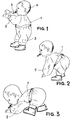
- the doll simulates a falling position by lowering its arms and resting them on the floor while tilting the trunk forwards.
- the arms seem to yield towards the front while the legs open, both at the same time, one towards the front and the other towards the rear.
- the head lifts backwards so that the direction of the eyes is maintained substantially forwards.
- the overall movement is reversed and the doll manages to stand up. During the whole of this second phase of the movement, the doll calls for its mom.
- the doll is fitted with a mechanism installed in the trunk and driven by a small electric motor fed from batteries installed inside the shoes.
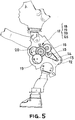
- the electric motor is able to drive, in both rotation directions, a clutch assembly comprising a central drive wheel and two side-driven wheels or pinions, one on each side, which rotate in a mutually excluding manner depending on the rotation direction of the drive wheel, in view that its laterally facing surfaces are fitted with saw teeth of an appropriate design.
- Each oscillating lever ends, at a lower part thereof, farthest from the oscillating shaft, in an oscillating toothed sector which meshes with a toothed circular sector joined in rotating fashion to a respective leg, although allowing for diametrical oscillation of same.
- This enables relative movement between the trunk and the legs, thereby achieving an absolute movement for the trunk or the legs as a function of the convenient immobilized condition of the other element.
- These movements are performed with a great deal of precision, smoothness and realism, deriving from the channel-stub coupling, and may be different for each leg in view that each has its own associated central wheel side channel.
- an outward movement of the legs is achieved, simultaneous to the rotation of the legs, as a result of the joint axes being substantially outward and downwards, as opposed to horizontally, oriented.
- the doll that is the object of the invention comprises a trunk 1 with jointed arms 2 and legs 3 capable of moving in response to orders from the internal mechanism.
- the head 4 moves in a front-to-rear direction, accompanying the movement of the trunk, as described further on, and may be rotated by hand to any desired lateral position.
- a pacifier 5 activates the internal mechanism when removed from the doll's mouth.
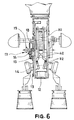
- Figure 4 shows the internal mechanism in the trunk 1 of the doll that is the object of the invention, the arms 2 being jointed over an arm shaft 6 and the legs 3 over respective leg joints 7.
- the head 4 is mounted on a head fork 8 that rotates over two fork protrusions 9 integral to the doll's trunk 1.
- a head spring 10 attaches the head 4 to the trunk 1 to provide it with improved smoothness of motion while a leg spring 11 partially balances the weight of the trunk 1 when the trunk is in a horizontal position.
- the trunk 1 is fitted with an electric motor 12, the motor pulley 13 of which couples onto an endless belt 14.
- the belt moves a set of reducer trains 15 and 16 which transmit movement to the clutch assembly 17, composed of a drive wheel 18, a driven wheel 19 and a driven pinion 20 located one on each side of and coaxial to the drive wheel 18 which provides motion through facing front sides having respective surfaces in the form of associated saw teeth 21 and 22.
- each driven wheel and pinion 19, 20 can be rotated only in opposite directions in respect to drive wheel 18.
- the first phase driven wheel 19 or the second phase driven pinion 20 are made to rotate.
- the mechanism Meshed with the first phase driven wheel 19, the mechanism presents a first phase shaft pinion 23, the integral shaft 24 of which drives two opposite eccentric discs 25. Onto these discs are attached respective free connecting rods 26, 27; upon rotation of the first phase shaft 24 and the associated opposite eccentric discs 25, reciprocating vertical movement of the free connecting rods 26, 27 is generated. Furthermore, and meshing with second phase driven pinion 20, the mechanism presents a second phase shaft wheel 28 integral to the second phase shaft 29 bearing two integrally rotating second phase pinions 30, 31.
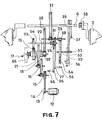
- the first 2nd phase pinion 30 meshes with a toothed arm wheel 33 with an arm channel 34 on its front face placed at a variable distance from shaft 35 of arm wheel 33 (see Figures 7 and 10).
- this arm channel 34 is inserted a stub 36 of a rack 37 which meshes with an arm pinion 38 coaxial and integral to arm shaft 6 and to arm 2 (for the purpose of clarity, Figure 7 shows an exploded view of rack 37 and arm 2).
- the rack 37 performs a reciprocating linear movement in the direction of the arrow, thereby providing oscillating rotation to arm pinion 38, and consequently to both arms 2.
- the linear movement of rack 37 derives from the fact that the rack's movement is limited by the arm shaft 6 and the arm wheel shaft 35 which cross the rack 37 along respective aligned rack grooves 39 (see Figure 10).
- the second 2nd phase pinion 31 meshes with central wheel 32 which rotates freely around arm shaft 6.
- This central wheel 32 presents, on each of its faces, a trunk channel 40 placed at a variable distance from arm shaft 6, into which channel is inserted the trunk stub 41 of oscillating lever 42 that is hinged onto an oscillating shaft 43 fixed to the doll's trunk 1 and is provided with a groove 70 allowing the arm shaft 6 to pass.
- the doll's legs 3 finish at their lower end in a shoe 44 containing batteries 45 for electrically driving the doll's mechanism.
- the doll's overall center of gravity is thus lowered, improving the doll's stability and enabling it to raise itself back to an upright position.
- the upper end of the doll's legs 3 finish in a sliding zone 46 having the general form of a rectangular section plate strongly angled towards the exterior.
- This rectangular sliding zone 46 can move freely in an axial direction in view that it is housed in a rectangular routing 47 lodging the leg joints 7. In this manner, the leg 3 can rotate when driven by leg joints 7 and can furthermore slide in both directions of the leg joint 7 diameter.
- the legs 3 can thus move in a vertical directions when a leg stub 53 is acted on by a leg fork 54 which, being hinged to a fork shaft 55 attached to trunk 1, receives an oscillating movement through stubs 56 in the free connecting rods 26 and 27.
- the leg stub 53 is located outside the leg fork 54, and therefore the position of leg 3 is defined axially by the action of an inner spring 67 which presses the support 68 of leg joint 7 and acts downwards on the sliding zone 46 of leg 3.
- Leg joint 7 housing the sliding zone 46 of leg 3 in its rectangular routing 47, is mounted by means of two screws 48 on a joint support 49 fitted with two attachment stubs 50 which penetrate in the corresponding holes in leg joint 7 and guarantee an exact angular positioning of the joint and consequently of the leg.
- joint support 49 capable of rotating freely inside a joint bearing 51 attached to trunk 1, presents a circular toothed sector 52 which meshes with a toothed sector fitted on oscillating lever 42 (see Figures 11 and 16).
- Arm shaft 6 carries a freely rotating head cam 57 which is moved by the central wheel 32 through indentations 58 in the facing surfaces of both parts.
- This head cam 57 acts on a driven stub 59 in a head auxiliary lever 60 hinged over an inner projection of head fork protrusion 9, enabling the head 4 to move when acted upon by head stub 61 in groove 62 of head fork 8 (see Figures 17 and 18).
- Trunk 1 is fitted with a sound emitting device 63 and a microswitch 64 activated by central wheel 32.
- the first phase shaft pinion 23 rotates, carrying with it the first phase shaft 24 and the opposite eccentric discs 25, generating the vertical reciprocating movement of the free connecting rods 26, 27.
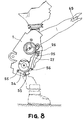
- Each of these free connecting rods 26, 27 is fitted with a free connecting rod stub 56 which transmits reciprocating movement to leg fork 54 which, upon securing leg stub 53, conveys a vertical reciprocating movement to leg 3 in respect to the doll's trunk 1 and thus simulates an unsteady walking motion (see Figures 8 and 9).
- the sound device 63 is attached to the rear portion of trunk 1, as can be seen in Figure 4. This device may correspond to any of the known types found in the market; we shall not describe its electrical connections to the various elements in view that these may be easily understood by any expert on the subject.
- the doll's hands are released, the doll continues to walk for some time with its unsteady gait and babbling noise, while a conventional timer is activated which after a specified period of time reverses the rotation of electric motor 12 and thus starts the second phase of the doll's movement.
- the babbling becomes a call for its mom while the trunk acquires a tilting stance, the legs become separated and the arms lowered and ready to rest on the floor.
- the first 2nd phase pinion 30 moves the arms 2 via arm wheel 33, arm channel 34, rack stub 36, rack 37 and arm pinion 38, with arm channel 34 presenting an appropriate configuration designed to achieve the desired coordination of arms movement and simultaneous trunk and legs movement.
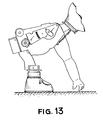
- the second 2nd phase pinion 31 generates the initial forward movement of the trunk, up to a point where the arms rest on the floor, as shown in Figure 13. This is achieved by the rotation of central wheel 32, the trunk channel 40 of which pulls the trunk stub 41 and with it the oscillating lever 42 which rotates around its oscillating shaft 43.
- the oscillating toothed sector 66 at the end of oscillating lever 42 thus varies its relative position in respect to the toothed circular sector 52 that is rotatingly attached to the legs 3; in view that the legs are unable to move because of the weight of the batteries 45 inside the shoes 44 and the leg's resting position on the floor, the whole of the doll's trunk 1 tilts forwards (see sequence in Figures 12 and 13).
- the arm wheel 33 and the central wheel 32 have ended their cycle after a 360° turn and the latter activates a stop microswitch 64 which cuts the electric supply to the motor 12, stops the second phase of the movement and activates a second timer which, after a specified time, once again connects motor 12 in reverse and again activates the unsteady walking of the first phase of the movement.
Landscapes
- Toys (AREA)
Applications Claiming Priority (4)
| Application Number | Priority Date | Filing Date | Title |
|---|---|---|---|
| ES9800387 | 1998-02-24 | ||
| ES9800387 | 1998-02-24 | ||
| ES9802513 | 1998-11-30 | ||
| ES9802513A ES2147534B1 (es) | 1998-11-30 | 1998-11-30 | Muñeca que se desplaza con paso vacilante y con movimientos de caida y recuperacion de la verticalidad. |
Publications (3)
| Publication Number | Publication Date |
|---|---|
| EP0943363A2 true EP0943363A2 (de) | 1999-09-22 |
| EP0943363A3 EP0943363A3 (de) | 2000-06-28 |
| EP0943363B1 EP0943363B1 (de) | 2004-04-07 |
Family
ID=26155129
Family Applications (1)
| Application Number | Title | Priority Date | Filing Date |
|---|---|---|---|
| EP98500285A Expired - Lifetime EP0943363B1 (de) | 1998-02-24 | 1998-12-30 | Puppe mit unsicherem Gang |
Country Status (3)
| Country | Link |
|---|---|
| US (1) | US6095887A (de) |
| EP (1) | EP0943363B1 (de) |
| PT (1) | PT943363E (de) |
Families Citing this family (8)
| Publication number | Priority date | Publication date | Assignee | Title |
|---|---|---|---|---|
| EP1120740B1 (de) | 1999-05-10 | 2007-10-03 | Sony Corporation | Robotervorrichtung, steuerverfahren und aufzeichnungsmedium |
| US6257950B1 (en) * | 2000-05-12 | 2001-07-10 | Jamal M. Saleh | Self-propelled toy |
| ES2201856B1 (es) * | 2001-03-23 | 2005-05-16 | Fabricas Agrupadas De Muñecas De Onil, S.A. | Muñeco que reacciona a la voz y a las caricias, acostandose o sentandose. |
| US7938708B2 (en) * | 2005-11-03 | 2011-05-10 | Mattel, Inc. | Articulated walking toy device |
| US20070123142A1 (en) * | 2005-11-29 | 2007-05-31 | Maddocks Richard J | Realistic coordinating of specific body part movements in mechanical toys |
| CN101437587B (zh) * | 2006-05-04 | 2011-05-11 | 美泰有限公司 | 铰接行走玩具装置 |
| US8414350B2 (en) * | 2008-08-18 | 2013-04-09 | Rehco, Llc | Figure with controlled motorized movements |
| US8956198B1 (en) | 2010-09-27 | 2015-02-17 | Mattel, Inc. | Walking toy |
Family Cites Families (8)
| Publication number | Priority date | Publication date | Assignee | Title |
|---|---|---|---|---|
| US3514899A (en) * | 1968-04-26 | 1970-06-02 | Topper Corp | Doll having electrical action-producing mechanism responsive to actuators on separate articles |
| US3583098A (en) * | 1969-06-02 | 1971-06-08 | Mattel Inc | Dancing walking doll |
| US4312150A (en) * | 1979-02-09 | 1982-01-26 | Marvin Glass & Associates | Animated doll |
| US4563163A (en) * | 1985-01-29 | 1986-01-07 | Marvin Glass & Associates | Stand up doll |
| JPS639473A (ja) * | 1986-07-01 | 1988-01-16 | イワヤ株式会社 | 動物活動玩具 |
| US5030161A (en) * | 1988-02-19 | 1991-07-09 | Irwin Toy Limited | All-fours walking doll |
| US5088954A (en) * | 1991-01-25 | 1992-02-18 | Breslow, Morrison, Terzian & Associates, Inc. | Manually assisted and controlled walking doll |
| US5224896A (en) * | 1992-01-24 | 1993-07-06 | Breslow, Morrison, Terzian & Associates, Inc. | Ambulatory doll |
-
1998
- 1998-12-29 US US09/222,205 patent/US6095887A/en not_active Expired - Fee Related
- 1998-12-30 EP EP98500285A patent/EP0943363B1/de not_active Expired - Lifetime
- 1998-12-30 PT PT98500285T patent/PT943363E/pt unknown
Also Published As
| Publication number | Publication date |
|---|---|
| US6095887A (en) | 2000-08-01 |
| EP0943363B1 (de) | 2004-04-07 |
| EP0943363A3 (de) | 2000-06-28 |
| PT943363E (pt) | 2004-08-31 |
Similar Documents
| Publication | Publication Date | Title |
|---|---|---|
| US6095887A (en) | Doll capable of walking with unsteady steps and with falling and upright recovery motions | |
| US6579143B1 (en) | Twisting and dancing figure | |
| US6120343A (en) | Mechanism for moving the lower limbs of a toy figure | |
| US4943256A (en) | Amusement device propelled by an eccentric apparatus | |
| JPH0449435B2 (de) | ||
| US3425154A (en) | Walking mechanism | |
| US3940879A (en) | Walking doll | |
| US5030161A (en) | All-fours walking doll | |
| EP1073501A1 (de) | Vierbeiniges spielzeug mit verbesserter beinbewegung | |
| US3922813A (en) | Doll with motorized legs driven in unison and arms driven in unison thereby | |
| JP3195058U (ja) | 歩行玩具 | |
| US7163430B1 (en) | Walking toy figure | |
| US5842906A (en) | Walking mechanism for toys | |
| JP3439172B2 (ja) | 可動装置及びその付属装置 | |
| JPH0417197Y2 (de) | ||
| GB2250214A (en) | Walking toy | |
| US725432A (en) | Mechanical toy. | |
| JP3641029B2 (ja) | 可動人形体 | |
| JP2004129957A (ja) | 二足歩行玩具 | |
| JP3076721B2 (ja) | 歩行動物玩具 | |
| JP3043944U (ja) | 歩行玩具 | |
| CN222788441U (zh) | 玩具 | |
| JPH0239512Y2 (de) | ||
| JPH02237Y2 (de) | ||
| JPS6121104Y2 (de) |
Legal Events
| Date | Code | Title | Description |
|---|---|---|---|
| PUAI | Public reference made under article 153(3) epc to a published international application that has entered the european phase |
Free format text: ORIGINAL CODE: 0009012 |
|
| AK | Designated contracting states |
Kind code of ref document: A2 Designated state(s): BE FR GB IE IT LU NL PT |
|
| AX | Request for extension of the european patent |
Free format text: AL;LT;LV;MK;RO;SI |
|
| PUAL | Search report despatched |
Free format text: ORIGINAL CODE: 0009013 |
|
| AK | Designated contracting states |
Kind code of ref document: A3 Designated state(s): AT BE CH CY DE DK ES FI FR GB GR IE IT LI LU MC NL PT SE |
|
| AX | Request for extension of the european patent |
Free format text: AL;LT;LV;MK;RO;SI |
|
| AKX | Designation fees paid | ||
| 17P | Request for examination filed |
Effective date: 20000719 |
|
| RBV | Designated contracting states (corrected) |
Designated state(s): BE FR GB IE IT LU NL |
|
| REG | Reference to a national code |
Ref country code: DE Ref legal event code: 8566 |
|
| RBV | Designated contracting states (corrected) |
Designated state(s): BE FR GB IE IT LU NL PT |
|
| GRAP | Despatch of communication of intention to grant a patent |
Free format text: ORIGINAL CODE: EPIDOSNIGR1 |
|
| GRAS | Grant fee paid |
Free format text: ORIGINAL CODE: EPIDOSNIGR3 |
|
| GRAA | (expected) grant |
Free format text: ORIGINAL CODE: 0009210 |
|
| RAP1 | Party data changed (applicant data changed or rights of an application transferred) |
Owner name: FABRICAS AGRUPADAS DE MUNECAS DE ONIL, S.A. |
|
| AK | Designated contracting states |
Kind code of ref document: B1 Designated state(s): BE FR GB IE IT LU NL PT |
|
| REG | Reference to a national code |
Ref country code: GB Ref legal event code: FG4D |
|
| REG | Reference to a national code |
Ref country code: IE Ref legal event code: FG4D |
|
| REG | Reference to a national code |
Ref country code: PT Ref legal event code: SC4A Free format text: AVAILABILITY OF NATIONAL TRANSLATION Effective date: 20040616 |
|
| NLR4 | Nl: receipt of corrected translation in the netherlands language at the initiative of the proprietor of the patent | ||
| ET | Fr: translation filed | ||
| PLBE | No opposition filed within time limit |
Free format text: ORIGINAL CODE: 0009261 |
|
| STAA | Information on the status of an ep patent application or granted ep patent |
Free format text: STATUS: NO OPPOSITION FILED WITHIN TIME LIMIT |
|
| 26N | No opposition filed |
Effective date: 20050110 |
|
| REG | Reference to a national code |
Ref country code: PT Ref legal event code: PD4A Owner name: FABRICAS AGRUPADAS DE MUNECAS DE ONIL, S.A., ES Effective date: 20070924 Ref country code: PT Ref legal event code: PC4A Owner name: INVERSIONES FADIVER, SA, ES Effective date: 20070924 |
|
| BECN | Be: change of holder's name |
Owner name: FABRICAS AGRUPADAS DE MUNECAS DE ONIL, S.A. Effective date: 20071122 |
|
| REG | Reference to a national code |
Ref country code: GB Ref legal event code: 732E |
|
| PGFP | Annual fee paid to national office [announced via postgrant information from national office to epo] |
Ref country code: NL Payment date: 20071203 Year of fee payment: 10 Ref country code: LU Payment date: 20071231 Year of fee payment: 10 |
|
| NLS | Nl: assignments of ep-patents |
Owner name: INVERSIONES FADIVER, S.A. Effective date: 20071203 |
|
| NLT1 | Nl: modifications of names registered in virtue of documents presented to the patent office pursuant to art. 16 a, paragraph 1 |
Owner name: FABRICAS AGRUPADAS DE MUNECAS DE ONIL, S.A. |
|
| REG | Reference to a national code |
Ref country code: FR Ref legal event code: TP Ref country code: FR Ref legal event code: CD |
|
| PGFP | Annual fee paid to national office [announced via postgrant information from national office to epo] |
Ref country code: GB Payment date: 20071227 Year of fee payment: 10 Ref country code: FR Payment date: 20071210 Year of fee payment: 10 |
|
| PGFP | Annual fee paid to national office [announced via postgrant information from national office to epo] |
Ref country code: PT Payment date: 20071210 Year of fee payment: 10 Ref country code: IT Payment date: 20071228 Year of fee payment: 10 |
|
| PGFP | Annual fee paid to national office [announced via postgrant information from national office to epo] |
Ref country code: BE Payment date: 20080314 Year of fee payment: 10 |
|
| BERE | Be: lapsed |
Owner name: FABRICAS AGRUPADAS DE MUNECAS DE ONIL, S.A. Effective date: 20081231 |
|
| REG | Reference to a national code |
Ref country code: PT Ref legal event code: MM4A Free format text: LAPSE DUE TO NON-PAYMENT OF FEES Effective date: 20090630 |
|
| GBPC | Gb: european patent ceased through non-payment of renewal fee |
Effective date: 20081230 |
|
| PG25 | Lapsed in a contracting state [announced via postgrant information from national office to epo] |
Ref country code: PT Free format text: LAPSE BECAUSE OF NON-PAYMENT OF DUE FEES Effective date: 20090630 |
|
| PGFP | Annual fee paid to national office [announced via postgrant information from national office to epo] |
Ref country code: IE Payment date: 20071212 Year of fee payment: 10 |
|
| NLV4 | Nl: lapsed or anulled due to non-payment of the annual fee |
Effective date: 20090701 |
|
| PG25 | Lapsed in a contracting state [announced via postgrant information from national office to epo] |
Ref country code: BE Free format text: LAPSE BECAUSE OF NON-PAYMENT OF DUE FEES Effective date: 20081231 |
|
| REG | Reference to a national code |
Ref country code: FR Ref legal event code: ST Effective date: 20090831 |
|
| REG | Reference to a national code |
Ref country code: IE Ref legal event code: MM4A |
|
| PG25 | Lapsed in a contracting state [announced via postgrant information from national office to epo] |
Ref country code: NL Free format text: LAPSE BECAUSE OF NON-PAYMENT OF DUE FEES Effective date: 20090701 Ref country code: GB Free format text: LAPSE BECAUSE OF NON-PAYMENT OF DUE FEES Effective date: 20081230 |
|
| PG25 | Lapsed in a contracting state [announced via postgrant information from national office to epo] |
Ref country code: IE Free format text: LAPSE BECAUSE OF NON-PAYMENT OF DUE FEES Effective date: 20081230 |
|
| PG25 | Lapsed in a contracting state [announced via postgrant information from national office to epo] |
Ref country code: FR Free format text: LAPSE BECAUSE OF NON-PAYMENT OF DUE FEES Effective date: 20081231 |
|
| PG25 | Lapsed in a contracting state [announced via postgrant information from national office to epo] |
Ref country code: LU Free format text: LAPSE BECAUSE OF NON-PAYMENT OF DUE FEES Effective date: 20081230 |
|
| PG25 | Lapsed in a contracting state [announced via postgrant information from national office to epo] |
Ref country code: IT Free format text: LAPSE BECAUSE OF NON-PAYMENT OF DUE FEES Effective date: 20081230 |