EP0943375A1 - Verfahren und Einrichtung zur Bodensanierung - Google Patents
Verfahren und Einrichtung zur Bodensanierung Download PDFInfo
- Publication number
- EP0943375A1 EP0943375A1 EP97203405A EP97203405A EP0943375A1 EP 0943375 A1 EP0943375 A1 EP 0943375A1 EP 97203405 A EP97203405 A EP 97203405A EP 97203405 A EP97203405 A EP 97203405A EP 0943375 A1 EP0943375 A1 EP 0943375A1
- Authority
- EP
- European Patent Office
- Prior art keywords
- container
- well
- liquid
- opening
- water
- Prior art date
- Legal status (The legal status is an assumption and is not a legal conclusion. Google has not performed a legal analysis and makes no representation as to the accuracy of the status listed.)
- Withdrawn
Links
- 238000000034 method Methods 0.000 title claims abstract description 30
- 238000009434 installation Methods 0.000 title claims abstract description 21
- 239000002689 soil Substances 0.000 title claims abstract description 16
- 238000005067 remediation Methods 0.000 title claims description 3
- 239000007788 liquid Substances 0.000 claims abstract description 123
- 239000000356 contaminant Substances 0.000 claims abstract description 77
- XLYOFNOQVPJJNP-UHFFFAOYSA-N water Substances O XLYOFNOQVPJJNP-UHFFFAOYSA-N 0.000 claims abstract description 65
- 238000005086 pumping Methods 0.000 claims abstract description 56
- 230000007423 decrease Effects 0.000 claims abstract description 4
- 239000012071 phase Substances 0.000 claims description 42
- 238000001514 detection method Methods 0.000 claims description 6
- 238000011012 sanitization Methods 0.000 claims description 6
- 238000002347 injection Methods 0.000 claims description 5
- 239000007924 injection Substances 0.000 claims description 5
- 239000007791 liquid phase Substances 0.000 claims description 2
- 239000000523 sample Substances 0.000 description 7
- 238000004140 cleaning Methods 0.000 description 2
- 239000000295 fuel oil Substances 0.000 description 2
- 229930195733 hydrocarbon Natural products 0.000 description 2
- 150000002430 hydrocarbons Chemical class 0.000 description 2
- 238000012423 maintenance Methods 0.000 description 2
- 230000037452 priming Effects 0.000 description 2
- 239000008346 aqueous phase Substances 0.000 description 1
- 230000015572 biosynthetic process Effects 0.000 description 1
- 239000004020 conductor Substances 0.000 description 1
- 238000006073 displacement reaction Methods 0.000 description 1
- 239000000463 material Substances 0.000 description 1
- 239000002245 particle Substances 0.000 description 1
- 239000003208 petroleum Substances 0.000 description 1
- 239000004033 plastic Substances 0.000 description 1
- 239000004417 polycarbonate Substances 0.000 description 1
- 229920000515 polycarbonate Polymers 0.000 description 1
- 239000007787 solid Substances 0.000 description 1
- 229910001220 stainless steel Inorganic materials 0.000 description 1
- 239000010935 stainless steel Substances 0.000 description 1
- 235000020681 well water Nutrition 0.000 description 1
- 239000002349 well water Substances 0.000 description 1
Images



Classifications
-
- E—FIXED CONSTRUCTIONS
- E21—EARTH OR ROCK DRILLING; MINING
- E21B—EARTH OR ROCK DRILLING; OBTAINING OIL, GAS, WATER, SOLUBLE OR MELTABLE MATERIALS OR A SLURRY OF MINERALS FROM WELLS
- E21B43/00—Methods or apparatus for obtaining oil, gas, water, soluble or meltable materials or a slurry of minerals from wells
- E21B43/34—Arrangements for separating materials produced by the well
- E21B43/38—Arrangements for separating materials produced by the well in the well
-
- B—PERFORMING OPERATIONS; TRANSPORTING
- B09—DISPOSAL OF SOLID WASTE; RECLAMATION OF CONTAMINATED SOIL
- B09C—RECLAMATION OF CONTAMINATED SOIL
- B09C1/00—Reclamation of contaminated soil
- B09C1/002—Reclamation of contaminated soil involving in-situ ground water treatment
-
- B—PERFORMING OPERATIONS; TRANSPORTING
- B09—DISPOSAL OF SOLID WASTE; RECLAMATION OF CONTAMINATED SOIL
- B09C—RECLAMATION OF CONTAMINATED SOIL
- B09C1/00—Reclamation of contaminated soil
- B09C1/007—Reclamation of contaminated soil by removing contaminants floating on the water table
-
- E—FIXED CONSTRUCTIONS
- E21—EARTH OR ROCK DRILLING; MINING
- E21B—EARTH OR ROCK DRILLING; OBTAINING OIL, GAS, WATER, SOLUBLE OR MELTABLE MATERIALS OR A SLURRY OF MINERALS FROM WELLS
- E21B43/00—Methods or apparatus for obtaining oil, gas, water, soluble or meltable materials or a slurry of minerals from wells
- E21B43/12—Methods or apparatus for controlling the flow of the obtained fluid to or in wells
- E21B43/121—Lifting well fluids
-
- B—PERFORMING OPERATIONS; TRANSPORTING
- B09—DISPOSAL OF SOLID WASTE; RECLAMATION OF CONTAMINATED SOIL
- B09C—RECLAMATION OF CONTAMINATED SOIL
- B09C2101/00—In situ
Definitions
- the subject of the present invention is a method for cleaning up soil contaminated with liquid contaminants of density less than 1 and forming at least partially a distinct phase with respect to water, in which we plan in the soil to be sanitized a series of separate wells capable of collecting water and products liquid contaminants forming a phase on the surface of the collected water.
- the method according to the invention aims to remedy these drawbacks and relates to a process consuming a minimum amount of energy for pumping water and liquid contaminants.
- water is pumped out of the well to bring the phase of liquid contaminants at the opening of the container placed in said well.
- the container or a part associated therewith to bring the opening of the container to the level of the phase liquid contaminants.
- a volume of liquid is pumped out of the container, while as soon as the opening is no longer substantially immersed in water, stop pumping liquid out of the container.
- water is introduced into the well.
- the well is allowed to fill with water and liquid contaminants from the soil to be remediated.
- the opening of the container is located at a distance of at least 50 cm from the bottom of the well.
- the opening of the container is located at most 100 cm from the bottom of the well.
- wells are advantageously formed having a liquid-permeable side wall.
- the bottom of the wells is provided with an impermeable tank and / or with a tank the horizontal cross section of which decreases the closer we get to the bottom thereof.
- control unit includes a timer or timer stopping pumping of liquid out of the container after a period of time determined.
- control unit provides the injection of water by a piping opening into the well when it controls the pumping of liquid out of the container.
- the installation comprises at least one vacuum pump connected by a pipe to each of the containers to create a vacuum inside the container and a suction of liquid into the container through the lower opening of this one.
- control unit comprises a timer or timer for pumping water out of the well intermittently.
- the control unit 16 includes a timer or timer 17 stopping the pumping liquid out of the container after a specified period of time.
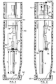
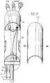
- FIGS. 2 and 3 show in section the bottom of a well 2 provided with a container 1, while Figure 4 is a perspective view of the container 1.
- the well 1 is formed by a longitudinal hole whose side wall 100 is formed by a permeable sheath liquids.
- the bottom of the well is advantageously waterproof and is formed by a bowl 101.
- the cross section of the part of the well adjacent to its bottom 102 decreases the closer we get to it. This shape is advantageous because the bottom of the well reaches the level more quickly of the opening of the container 1.
- the lower opening O of the container made of material plastic (PVC, polycarbonate, ...) is for example 75 cm from the bottom of the well.
- the container 1 defines a substantially cylindrical chamber 103 extended by a duct 104 of semi-circular section.
- the lower part of a pipe 8 for the pumping of liquid out of the well passes through the chamber 103 and the conduit 104.
- the free end of line 8 is adjacent to the bottom of the well, but is preferably located at a sufficient distance from it to prevent this end is immersed in a deposit of solid particles.
- This free end of the pipe is located below the opening O of the container.
- the vertical distance D between the opening O of the container 1 and the opening of the end free of line 8 is at least 10 cm (for example between 20 and 50 cm).
- the upper part of the container is provided with a nozzle 105 forming a passage between the chamber 103 and the piping 5 for sucking out of the container of the liquids.
- the probe high 10 determines the presence of contaminating liquids in chamber 103 or more exactly when the chamber is substantially completely filled with contaminating liquids.
- the low probe is located near the opening O of the container 1.
- the probes 10, 11 are carried by two trays 110, 111 pierced with a hole.
- the lower plate 111 also carries the end of an electrical conductor 112 intended to form a mass or a reference for the high probe 10.
- the information (electrical pulses) from the probes is sent by cables 116,117 to the control unit 16, the latter also being connected by a cable 118 to earth 112.
- a cover 119 makes it possible to close the space or volume located between the two trays 110,111. This cover is by example fixed by means of screws 120.
- FIG. 1 allows the implementation of a process remediation of soil contaminated with liquid density contaminating products less than 1 and at least partially forming a distinct phase with respect to water, in which a series of separate wells suitable for collect water and liquid contaminants forming a phase in the surface of the collected water, in which is placed in each of said wells a container having a lower end an upper end and a adjacent opening of its downward facing end, in which said filling is filled container by means of water, in which the opening of each container is brought to the level of the phase of liquid contaminants or in which the phase of liquid liquid contaminants at the opening of each container so that as this phase rises in the container towards its upper end, in which when the container contains a determined volume of liquid contaminants, at least partially pump this volume out of the container.
- Figures 5 to 9 show process steps for a container 1 placed in a well 2.
- the well 2 has a substantially circular cross section S with a diameter of between 5 and 15 cm, for example around 10 cm.
- the container has a maximum cross section SM less than the cross section of the well so that it can slide into said well.
- This section SM is advantageously circular and advantageously has a diameter such that a spacing E of 0.5 to 1.5 cm is created between the substantially cylindrical part of the container 1 and the internal wall of the well 2.
- Well 1 is refilled and the steps of pumping water out of the well and transferring liquid contaminants into well 2 are repeated until the probe 10 detects liquid contaminants, that is to say a volume Vmax of liquid contaminants in the container 1. (FIG. 8) At this time, the phase of liquid contaminants is pumped out of the container 1 using the pump 4 and the pipe 5 to bring it to a tank 31. During of this pumping, water is sucked into the container 1 through its opening O. To avoid that the opening O is no longer immersed in water, it is advantageous during this pumping step to inject through the line 13 of water in the well.
- the flow rate of water injected advantageously corresponds substantially to the flow rate of liquid contaminants pumped out of the container 1, so as to ensure that the well 2 contains a quantity of water sufficient to replace the volume of liquid contaminants pumped into the container.
- the cycle can then continue with steps for filling the well with liquids passing through the side wall of well 2, for draining water out of the well, for transfer of liquid contaminants into the container, etc.
- the control device 16 controls for the various containers 1 placed in the well 2, (and this advantageously independently) the pumping steps of water out of the wells, draining liquid contaminants out of the containers with preferably injection of water into the well.
- the pipe 8 for sucking water out of the well is provided at its free end with a non-return valve, this valve making it possible to ensure that the conduit 8 does not discharge by itself into the well during a stop of the pump 7.
- the pipe 5 is advantageously provided with the near its adjacent end of container 1, a non-return valve avoiding passage of liquid from the pipe to the container 1.
- Such non-return valves keep effortlessly a column of liquid in the pipes and therefore to facilitate the operation of pumps 4 and 7.
- the pumps are advantageously placed in surface, so as to facilitate their maintenance and so as to avoid having to immerse rotating mechanical parts.
- opening O for the suction of liquid contaminants with a density lower than that water is extended by a conduit 40 associated with a movable part 41 so as to be able position the level of the suction opening in the well.
- the displacement of the mobile part is controlled for example by a jack 42 controlled by the unit control 16.
- the sensor 11 is advantageously mounted on the movable tube 41. This embodiment is advantageous because it allows to maintain, at least for a period of time, the opening in the vicinity of the liquid contaminant phase without pumping water out of the well and despite the natural filling of the well with water and other liquids from the ground.
- FIG. 1 makes it possible to remediate soils polluted by hydrocarbons, such as fuel oil, petroleum, etc., by other liquid contaminants of density less than 1 and preferably substantially immiscible with water so as to ability to form a phase distinct from an aqueous phase or a phase rich in liquid contaminants.
- hydrocarbons such as fuel oil, petroleum, etc.
Landscapes
- Life Sciences & Earth Sciences (AREA)
- Engineering & Computer Science (AREA)
- Geology (AREA)
- Mining & Mineral Resources (AREA)
- Environmental & Geological Engineering (AREA)
- Fluid Mechanics (AREA)
- Physics & Mathematics (AREA)
- General Life Sciences & Earth Sciences (AREA)
- Geochemistry & Mineralogy (AREA)
- Soil Sciences (AREA)
- Hydrology & Water Resources (AREA)
- Water Supply & Treatment (AREA)
- Processing Of Solid Wastes (AREA)
Priority Applications (1)
| Application Number | Priority Date | Filing Date | Title |
|---|---|---|---|
| EP97203405A EP0943375A1 (de) | 1997-11-03 | 1997-11-03 | Verfahren und Einrichtung zur Bodensanierung |
Applications Claiming Priority (1)
| Application Number | Priority Date | Filing Date | Title |
|---|---|---|---|
| EP97203405A EP0943375A1 (de) | 1997-11-03 | 1997-11-03 | Verfahren und Einrichtung zur Bodensanierung |
Publications (1)
| Publication Number | Publication Date |
|---|---|
| EP0943375A1 true EP0943375A1 (de) | 1999-09-22 |
Family
ID=8228897
Family Applications (1)
| Application Number | Title | Priority Date | Filing Date |
|---|---|---|---|
| EP97203405A Withdrawn EP0943375A1 (de) | 1997-11-03 | 1997-11-03 | Verfahren und Einrichtung zur Bodensanierung |
Country Status (1)
| Country | Link |
|---|---|
| EP (1) | EP0943375A1 (de) |
Citations (6)
| Publication number | Priority date | Publication date | Assignee | Title |
|---|---|---|---|---|
| AT379120B (de) * | 1983-05-04 | 1985-11-25 | Gurschner Maria | Sanierbrunnen-anlage |
| US4625801A (en) * | 1983-07-13 | 1986-12-02 | Pump Engineer Associates, Inc. | Methods and apparatus for recovery of hydrocarbons from underground water tables |
| US4746423A (en) * | 1986-09-15 | 1988-05-24 | R. E. Wright Associates | In-well pump skimmer |
| US5128052A (en) * | 1991-01-15 | 1992-07-07 | Bullock Philip W | Wellbore liquid recovery apparatus and method |
| US5154538A (en) * | 1989-03-22 | 1992-10-13 | Preussag Aktiengesellschaft | Method and apparatus for removing a liquid phase floating on a surface of groundwater |
| US5207897A (en) * | 1991-05-20 | 1993-05-04 | Baird William E | Floating hydrocarbons separator pump with buoyant housing and two-chamber vertically moveable member |
-
1997
- 1997-11-03 EP EP97203405A patent/EP0943375A1/de not_active Withdrawn
Patent Citations (6)
| Publication number | Priority date | Publication date | Assignee | Title |
|---|---|---|---|---|
| AT379120B (de) * | 1983-05-04 | 1985-11-25 | Gurschner Maria | Sanierbrunnen-anlage |
| US4625801A (en) * | 1983-07-13 | 1986-12-02 | Pump Engineer Associates, Inc. | Methods and apparatus for recovery of hydrocarbons from underground water tables |
| US4746423A (en) * | 1986-09-15 | 1988-05-24 | R. E. Wright Associates | In-well pump skimmer |
| US5154538A (en) * | 1989-03-22 | 1992-10-13 | Preussag Aktiengesellschaft | Method and apparatus for removing a liquid phase floating on a surface of groundwater |
| US5128052A (en) * | 1991-01-15 | 1992-07-07 | Bullock Philip W | Wellbore liquid recovery apparatus and method |
| US5207897A (en) * | 1991-05-20 | 1993-05-04 | Baird William E | Floating hydrocarbons separator pump with buoyant housing and two-chamber vertically moveable member |
Similar Documents
| Publication | Publication Date | Title |
|---|---|---|
| CA1296598C (fr) | Dispositif de nettoyage d'une aiguille de prelevement d'un liquide | |
| FR2655470A1 (fr) | Nettoyeur haute pression equipe d'un ensemble de recuperation du liquide de nettoyage et des dechets. | |
| CA2971370A1 (fr) | Systeme de prelevement de sediments sur un fond d'un milieu liquide | |
| FR2494127A1 (fr) | Dispositif pour la decantation d'un fluide | |
| WO2007132073A1 (fr) | Systeme de nettoyage d'une cuve de petrole et procede de nettoyage d'une cuve de petrole | |
| EP0943375A1 (de) | Verfahren und Einrichtung zur Bodensanierung | |
| EP0063971A1 (de) | Einrichtung zur Probennahme von Flüssigkeiten | |
| FR2783345A1 (fr) | Procede et installation de remplissage de futs contenant des dechets dangereux | |
| FR2887904A1 (fr) | Dispositif distributeur d'un produit nettoyant | |
| FR2728292A1 (fr) | Poste de refoulement prefabrique pour eaux usees, eaux pluviales ou eaux industrielles | |
| EP0296917B1 (de) | Vorrichtung zur kontinuierlichen Zirkulation einer Flüssigkeit zur Probenahme oder Kontrolle dieser Flüssigkeit | |
| FR2792666A1 (fr) | Systeme et procede d'evacuation a depression pour eaux usees, et boite tampon utilisee | |
| EP0956165B1 (de) | Verfahren und vielzweckvorrichtung zur erhaltung metastabiler flüssigkeiten | |
| EP1091812B1 (de) | Verfahren zum reinigen eines ölspeichertanks und gerät zur verwirklichung des verfahrens | |
| EP1182355B1 (de) | Einrichtung zur Tiefbodendrainage | |
| CA1070104A (fr) | Installation pour l'impregnation de bois massif de pieces en bois et d'autres materiaux poreux au moyen de liquides | |
| FR2608566A1 (fr) | Tremie basculante | |
| EP2474674B1 (de) | Siphonvorrichtung mit automatischer Füllung | |
| EP0335452B1 (de) | Waschmaschine mit Überfluss | |
| EP2867416B1 (de) | Automatische spülvorrichtung zur steuerung des betriebs eines auslauffängers | |
| EP1518614B1 (de) | Vorrichtung und Verfahren zur Grundwassersanierung | |
| FR2821414A1 (fr) | Dispositif semi-enterre de captage de gaz | |
| FR2668593A1 (fr) | Appareil doseur de liquide a deux siphons. | |
| WO2005099922A1 (fr) | Dispositif et procede de depollution in situ de nappes souterraines | |
| WO2015092331A1 (fr) | Procédé d'injection de fluides dans une installation sous-marine |
Legal Events
| Date | Code | Title | Description |
|---|---|---|---|
| PUAI | Public reference made under article 153(3) epc to a published international application that has entered the european phase |
Free format text: ORIGINAL CODE: 0009012 |
|
| AK | Designated contracting states |
Kind code of ref document: A1 Designated state(s): AT BE CH DE DK ES FI FR GB GR IE IT LI LU MC NL PT SE |
|
| AKX | Designation fees paid | ||
| REG | Reference to a national code |
Ref country code: DE Ref legal event code: 8566 |
|
| STAA | Information on the status of an ep patent application or granted ep patent |
Free format text: STATUS: THE APPLICATION IS DEEMED TO BE WITHDRAWN |
|
| 18D | Application deemed to be withdrawn |
Effective date: 20000323 |