EP0943378A2 - Vorrichtung zur Führung und Querverschiebung von Walzdrahtwindungen - Google Patents
Vorrichtung zur Führung und Querverschiebung von Walzdrahtwindungen Download PDFInfo
- Publication number
- EP0943378A2 EP0943378A2 EP99104713A EP99104713A EP0943378A2 EP 0943378 A2 EP0943378 A2 EP 0943378A2 EP 99104713 A EP99104713 A EP 99104713A EP 99104713 A EP99104713 A EP 99104713A EP 0943378 A2 EP0943378 A2 EP 0943378A2
- Authority
- EP
- European Patent Office
- Prior art keywords
- bundle
- swivel
- forming chamber
- chamber
- thrust drive
- Prior art date
- Legal status (The legal status is an assumption and is not a legal conclusion. Google has not performed a legal analysis and makes no representation as to the accuracy of the status listed.)
- Withdrawn
Links
Images
Classifications
-
- B—PERFORMING OPERATIONS; TRANSPORTING
- B21—MECHANICAL METAL-WORKING WITHOUT ESSENTIALLY REMOVING MATERIAL; PUNCHING METAL
- B21C—MANUFACTURE OF METAL SHEETS, WIRE, RODS, TUBES, PROFILES OR LIKE SEMI-MANUFACTURED PRODUCTS OTHERWISE THAN BY ROLLING; AUXILIARY OPERATIONS USED IN CONNECTION WITH METAL-WORKING WITHOUT ESSENTIALLY REMOVING MATERIAL
- B21C47/00—Winding-up, coiling or winding-off metal wire, metal band or other flexible metal material characterised by features relevant to metal processing only
- B21C47/02—Winding-up or coiling
- B21C47/10—Winding-up or coiling by means of a moving guide
- B21C47/14—Winding-up or coiling by means of a moving guide by means of a rotating guide, e.g. laying the material around a stationary reel or drum
- B21C47/146—Controlling or influencing the laying pattern of the coils
Definitions
- the invention relates to a device for guiding and Transverse displacement of wire rod turns by means of a conveyor transported in an approximately horizontal position to form wire coils into an upright cylindrical bundling chamber to be thrown into the area of the interior of the bundle chamber insertable and extractable, which act on the wire rod windings Cross slide elements.
- Devices of this type come in a wide variety of forms has been developed; they serve the goal, which come from one, in a wire rod mill rolled wire by means of a winding layer, overlapping one another and possibly cooled on the conveyor or otherwise treated wire rod windings that their dropping into the bundle chamber depending on the transport speed, the wire diameter and its metallic Structure shifted more or less unevenly against each other lay on top of each other, load laterally and move that a bundle of evenly lying turns is formed becomes.
- the invention is based, the generic form of training the task to improve the device so that these listed Disadvantages are avoided.
- transverse displacement device swivel brackets suspended outside the bundle chamber consist of vertical slot recesses in the cylinder wall the fret chamber can be swung in and out of its interior are.
- This can be done according to the invention outside of Interior of the bundle chamber arranged with the swivel tabs connected, jointly or independently operable, hydraulic, pneumatic or electromagnetic thrust drive units be effected.
- the transverse displacement device swivel brackets suspended outside the bundle chamber consist of vertical slot recesses in the cylinder wall the fret chamber can be swung in and out of its interior are.
- This can be done according to the invention outside of Interior of the bundle chamber arranged with the swivel tabs connected, jointly or independently operable, hydraulic, pneumatic or electromagnetic thrust drive units be effected.
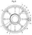
- Likewise in itself known, comprising the bundle forming chamber with a radial distance, rotatably mounted and drivable eccentric rings or cam rings or use individual cam drives as thrust drive units.
- the drives can be individually, sequentially or group-
- the swivel brackets should move into the Slot recesses of the Bundsenthunt be fitted, and the Surface section of the swivel brackets that acts on wire rod windings can, according to the invention, be flat or transverse to the tab longitudinal direction slightly arched and hardened and / or gliding Have coatings.
- the invention allows, besides avoiding the enumerated Disadvantages the length of the displacement of the swivel tabs and their Adjusting the cycle sequence according to the respective operating requirements to change or remove them completely from the drop area of the To bring out wire rod windings in the bundle forming chamber; this using conventional drive and control devices.
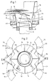
- the swivel tabs 3 are with With the help of these thrust drive units 4a and 4b through longitudinal slots 1c in the wall of the bundle forming chamber 1 in the interior of the latter Chamber swung in and out again. These swivel movements are with the help of a sequence control device, not shown for the thrust drive units 4a, 4b in the bundle forming chamber 1 moved in and out as indicated in Fig. 2, d. H. so that the turns S in the circumferential direction of an eccentric circle Center axis of the bundle chamber 1 are applied.
- the swivel plates 3 are with their thrust drive units 4a and 4b, as indicated by broken lines in Fig. 2, on segment support plates 14 arranged with the help of pressurized medium Piston-cylinder units 15 pivoted out of the support housing 1 can be to z.
- the Bundsentehunt 1 for that lateral removal of the mandrel 5 with the collar or that Highlighting the federal government in the event of operational disruptions or for assembly or To make repairs free. There is the possibility this process using appropriate safety switching elements trigger automatically.
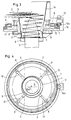
- the swivel tabs 3 are through one, mounted in the carrying case 1a, by a motor 12 Pinion 12a rotating eccentric 7 (see also Fig. 4) on rollers 8 mounted in transmission rods 13 against the effect of return springs 9 actuated.
Landscapes
- Engineering & Computer Science (AREA)
- Mechanical Engineering (AREA)
- Winding, Rewinding, Material Storage Devices (AREA)
- Wire Processing (AREA)
Abstract
Description
- Fig. 1
- die Vorrichtung von der Seite gesehen im Radialschnitt,
- Fig. 2
- die Draufsicht auf Fig. 1,
- Fig. 3
- eine andere Ausbildungsform der Vorrichtung ebenfalls im Radialschnitt,
- Fig. 4
- die Draufsicht auf Fig. 3 und
- Fig. 5
- eine andere Ausbildungsform der Vorrichtung in der Draufsicht entsprechend Fig. 4
- 1
- Bundbildekammer
- 1a
- (trichterförmiger) Einlaufteil
- 1b
- Traggehäuse
- 1c
- Längsschlitz
- 2
- Förderer
- 3
- Schwenklasche
- 4
- -
- 4a
- Exzenter
- 4b
- Kolbenzylinderaggregat
- 5
- Sammeldorn
- 6
- Bundtragplatte
- 7
- Exzenterring
- 8
- Rollen
- 9
- Rückzugfeder
- 10
- Nockenfläche
- 11
- Ring
- 12
- Motor
- 12a
- Zahnritzel
- 13
- Übertragungsgestänge
- 14
- Segmenttragplatte
- 15
- Kolbenzylinderaggregat
- S
- Walzdrahtwindung
Claims (10)
- Vorrichtung zur Führung und Querverschiebung von Walzdrahtwindungen, die mittels eines Förderers in etwa horizontaler Lage herantransportiert zur Bildung von Drahtbunden in eine aufrecht stehende zylindrische Bundbildekammer abgeworfen werden, mit in den Bereich des Innenraums der Bundbildekammer ein- und ausbringbaren, die Walzdrahtwindungen beaufschlagenden Querverschiebeeinrichtungen,
dadurch gekennzeichnet,
daß die Querverschiebeeinrichtungen aus, außerhalb der Bundbildekammer (1) hängend gelagerten Schwenklaschen (3) bestehen, die, durch senkrechte Schlitzausnehmungen (1a) in der Zylinderwand der Bundbildekammer (1) in deren Innenraum ein- und herausschwenkbar sind. - Vorrichtung nach Anspruch 1,
gekennzeichnet durch
außerhalb des Innenraums der Bundbildekammer (1) angeordnete, mit den Schwenklaschen (3) verbundene, gemeinsam oder unabhängig voneinander betätigbare Schubantriebaggregate (4a, 4b, 7, 11). - Vorrichtung nach Anspruch 2,
dadurch gekennzeichnet,
dass die Schubantriebsaggregate (4a, 4b) hydraulisch, pneumatisch oder elektromagnetisch angetrieben sind. - Vorrichtung nach Anspruch 2,
dadurch gekennzeichnet,
dass die Schubantriebsaggregate als, die Schwenklaschen (3) rückseitig beaufschlagende Nockenringe (4a, 10, 11) ausgebildet sind. - Vorrichtung nach Anspruch 2,
gekennzeichnet durch
einen, die Bundbildekammer (1) mit radialem Abstand umfassenden, drehbar gelagerten, Exzenter- oder Nockenring als Schubantriebsaggregat für die Schwenklaschen (3). - Vorrichtung nach einem oder mehreren der Ansprüche 2 bis 4,
gekennzeichnet durch
eine Einzel-, Folge- oder Gruppensteuerung für die Schubantriebsaggregate. - Vorrichtung nach einem oder mehreren der Ansprüche 1 bis 6,
dadurch gekennzeichnet,
daß die Schwenklaschen (3) mit leichtem Spiel in die Schlitzausnehmungen (1c) der Bundbildekammer (1) eingepaßt sind. - Vorrichtung nach einem oder mehreren der Ansprüche 1 bis 7,
dadurch gekennzeichnet,
daß die die Walzdrahtwindungen (S) beaufschlagenden Flächenabschnitte der Schwenklaschen (3) eben oder quer zu deren Längsrichtung leicht gewölbt verlaufen. - Vorrichtung nach einem oder mehreren der Ansprüche 1 bis 8,
dadurch gekennzeichnet,
daß die Schwenklaschen (3) gehärtete und/oder gleitfördernde Beschichtungen aufweisen. - Vorrichtung nach Anspruch 1,
gekennzeichnet durch
eine gegeneinander höhenversetzte Anordnung der Hängelager der Schwenklaschen 3.
Applications Claiming Priority (2)
| Application Number | Priority Date | Filing Date | Title |
|---|---|---|---|
| DE19811649A DE19811649A1 (de) | 1998-03-18 | 1998-03-18 | Vorrichtung zur Führung und Querverschiebung von Walzdrahtwindungen |
| DE19811649 | 1998-03-18 |
Publications (2)
| Publication Number | Publication Date |
|---|---|
| EP0943378A2 true EP0943378A2 (de) | 1999-09-22 |
| EP0943378A3 EP0943378A3 (de) | 2001-04-25 |
Family
ID=7861246
Family Applications (1)
| Application Number | Title | Priority Date | Filing Date |
|---|---|---|---|
| EP99104713A Withdrawn EP0943378A3 (de) | 1998-03-18 | 1999-03-10 | Vorrichtung zur Führung und Querverschiebung von Walzdrahtwindungen |
Country Status (4)
| Country | Link |
|---|---|
| US (1) | US6158683A (de) |
| EP (1) | EP0943378A3 (de) |
| JP (1) | JPH11319930A (de) |
| DE (1) | DE19811649A1 (de) |
Families Citing this family (6)
| Publication number | Priority date | Publication date | Assignee | Title |
|---|---|---|---|---|
| SE514295C2 (sv) * | 1999-05-03 | 2001-02-05 | Skaltek Ab | Förfarande och apparat för att till en ring upprulla en kabel, vajer, lina eller liknande |
| DE10026583A1 (de) * | 2000-05-30 | 2001-12-13 | Sket Walzwerkstechnik Gmbh | Vorrichtung zum Ablegen von Walzdrahtwindungen zu einem Drahtbund |
| DE10052731A1 (de) * | 2000-10-25 | 2002-05-02 | Sms Demag Ag | Vorrichtung zur Beeinflussung der Abwurf-Fallposition von in einen Bundbildeschacht abgeworfenen Walzdrahtwindungen |
| US9162269B2 (en) * | 2012-11-29 | 2015-10-20 | Primetals Technologies USA LLC | Coil forming apparatus and method |
| CN104759473A (zh) * | 2014-01-07 | 2015-07-08 | 安阳合力创科冶金新技术研发股份有限公司 | 交互式线材布料器 |
| EP3260212B1 (de) | 2016-06-20 | 2019-05-15 | Sund Birsta AB | Spulenformmaschine |
Family Cites Families (16)
| Publication number | Priority date | Publication date | Assignee | Title |
|---|---|---|---|---|
| US35440A (en) * | 1862-06-03 | Improvement in heaters | ||
| BR7601196A (pt) * | 1975-03-07 | 1976-09-14 | Barmag Barmer Maschf | Dispositivo transportador de cabo de fibras sinteticas,e,processo de sua operacao |
| DE2747706C3 (de) * | 1977-10-25 | 1986-06-19 | Officine Savio S.p.A., Pordenone | Vorrichtung zum Ablegen eines aus einer Vielzahl von Fäden bestehenden Kabels, insbesondere eines Kabels aus Chemiefasern o.dgl. in eine Kanne |
| JPS55143212A (en) * | 1979-04-13 | 1980-11-08 | Nippon Steel Corp | Ringgshaped wire material bundling method |
| US4376517A (en) * | 1980-04-16 | 1983-03-15 | Barmag Barmer Maschinenfabrik Ag | Method and apparatus for depositing yarn |
| DE3117181A1 (de) * | 1981-04-30 | 1982-11-25 | SMS Schloemann-Siemag AG, 4000 Düsseldorf | Vorrichtung zum durchtrennen eines drahtwindungsstranges in einer bundbildestation |
| DD253384B3 (de) * | 1986-10-22 | 1993-01-07 | Thaelmann Schwermaschbau Veb | Vorrichtung zur bildung von walzdraht- und schrottbunden |
| JPH05329538A (ja) * | 1991-04-22 | 1993-12-14 | Sumitomo Heavy Ind Ltd | 線材集束装置におけるばらまき装置 |
| US5273231A (en) * | 1992-08-03 | 1993-12-28 | Morgan Construction Company | Loop distributor for reforming station |
| IT1267252B1 (it) * | 1994-06-07 | 1997-01-28 | Danieli Off Mecc | Dispositivo per il deposito asimmetrico delle spire |
| IT1267251B1 (it) * | 1994-06-07 | 1997-01-28 | Danieli Off Mecc | Dispositivo per il deposito asimmetrico delle spire |
| US5779174A (en) * | 1996-04-02 | 1998-07-14 | Morgan Construction Company | Mounting arrangement for loop distributor in a reforming chamber |
| JP3268425B2 (ja) * | 1996-04-25 | 2002-03-25 | 住友重機械工業株式会社 | 線材コイル集束装置 |
| JPH10166050A (ja) * | 1996-12-02 | 1998-06-23 | Sumitomo Metal Ind Ltd | 線材コイルのリフォーミング装置 |
| DE19704421B4 (de) * | 1997-02-06 | 2008-04-10 | Sms Demag Ag | Vorrichtung zur Bildung von Bunden aus Walzdrahtschlingen |
| US6073873A (en) * | 1997-11-14 | 2000-06-13 | Morgan Construction Company | Coil forming apparatus and method |
-
1998
- 1998-03-18 DE DE19811649A patent/DE19811649A1/de not_active Withdrawn
-
1999
- 1999-03-10 EP EP99104713A patent/EP0943378A3/de not_active Withdrawn
- 1999-03-16 US US09/270,393 patent/US6158683A/en not_active Expired - Fee Related
- 1999-03-16 JP JP11070867A patent/JPH11319930A/ja not_active Withdrawn
Also Published As
| Publication number | Publication date |
|---|---|
| DE19811649A1 (de) | 1999-09-23 |
| EP0943378A3 (de) | 2001-04-25 |
| US6158683A (en) | 2000-12-12 |
| JPH11319930A (ja) | 1999-11-24 |
Similar Documents
| Publication | Publication Date | Title |
|---|---|---|
| EP0740508B1 (de) | Vorrichtung zum aufwickeln eines teigbandes | |
| DE2262148A1 (de) | Verfahren und vorrichtung zur zwischenspeicherung von bandfoermigen materialien, insbesondere metallband, in kontinuierlichen bandzufuehrungen zu verarbeitungsmaschinen | |
| EP0229888B1 (de) | Vorrichtung zum Speichern von in Schuppenformation anfallenden Druckprodukten | |
| EP0943378A2 (de) | Vorrichtung zur Führung und Querverschiebung von Walzdrahtwindungen | |
| DE4425079A1 (de) | Einrichtung zum Laden von Spulen in eine Verpackungsmaschine | |
| EP0566910B1 (de) | Vorrichtung zum Transport von zu Ringen gewickeltem Walzgut im Haspelbereich | |
| EP0569719B1 (de) | Bundtransportsystem | |
| EP1175945B1 (de) | Windungsleger mit Legerohr für schnellbewegten Walzdraht | |
| DE1761434A1 (de) | Vorrichtung zum Sammeln,Binden und Transportieren von draht- oder bandfoermigem Walzgut | |
| DE2905537C2 (de) | ||
| EP0607891B1 (de) | Vorrichtung zum Krumpfen, Recken, Trocknen, Appretieren, Färben, Zuführen od. dgl. von laufendem Textilgut, wie Bändern, Fäden od. dgl. | |
| EP0979689B1 (de) | Vorrichtung zum Minimieren der Bundhöhe von Draht in einer Bundbildekammer | |
| DE69803461T2 (de) | Vorrichtung zur kontinuierlichen übergabe von behältern in vertikaler richtung | |
| DE2917027A1 (de) | Verfahren und einrichtung zum foerdern von aufeinanderfolgenden heissen wicklungen | |
| EP0855456A2 (de) | Verfahren und Vorrichtung zum Transportieren voller Vorgarnspulen bzw. leerer Vorgarnhülsen | |
| DE19704421B4 (de) | Vorrichtung zur Bildung von Bunden aus Walzdrahtschlingen | |
| DE60109323T2 (de) | Vorrichtung und verfahren zum wickeln von bahnen | |
| DE2731559A1 (de) | Stapelvorrichtung fuer profilstaebe aus stahl | |
| DE3717295C2 (de) | ||
| EP0419447A1 (de) | Verfahren und Anlage zum Entzundern von Rundstahlstäben | |
| EP2511207B1 (de) | Vorrichtung zum Zwischenspeichern von in einer Schuppenanordnung aufwickelbaren, flächigen Erzeugnissen, insbesondere Druckprodukten, sowie Verfahren zum Betrieb einer solchen Vorrichtung | |
| DE3610138C2 (de) | ||
| EP0982248A1 (de) | Fördervorrichtung in einer Verpackungsmaschine | |
| CH671003A5 (de) | ||
| DE4304734C2 (de) | Vorrichtung zum Vereinzeln und Verschwenken von Schmalbandbunden |
Legal Events
| Date | Code | Title | Description |
|---|---|---|---|
| PUAI | Public reference made under article 153(3) epc to a published international application that has entered the european phase |
Free format text: ORIGINAL CODE: 0009012 |
|
| 17P | Request for examination filed |
Effective date: 19990326 |
|
| AK | Designated contracting states |
Kind code of ref document: A2 Designated state(s): AT DE GB IT SE |
|
| AX | Request for extension of the european patent |
Free format text: AL;LT;LV;MK;RO;SI |
|
| RAP1 | Party data changed (applicant data changed or rights of an application transferred) |
Owner name: SMS DEMAG AG |
|
| PUAL | Search report despatched |
Free format text: ORIGINAL CODE: 0009013 |
|
| AK | Designated contracting states |
Kind code of ref document: A3 Designated state(s): AT BE CH CY DE DK ES FI FR GB GR IE IT LI LU MC NL PT SE |
|
| AX | Request for extension of the european patent |
Free format text: AL;LT;LV;MK;RO;SI |
|
| AKX | Designation fees paid |
Free format text: AT DE GB IT SE |
|
| 17Q | First examination report despatched |
Effective date: 20030425 |
|
| STAA | Information on the status of an ep patent application or granted ep patent |
Free format text: STATUS: THE APPLICATION IS DEEMED TO BE WITHDRAWN |
|
| 18D | Application deemed to be withdrawn |
Effective date: 20030906 |