EP0943423A2 - Dispositif de chauffage pour un système de fabrication de carton ondulé - Google Patents
Dispositif de chauffage pour un système de fabrication de carton ondulé Download PDFInfo
- Publication number
- EP0943423A2 EP0943423A2 EP99103203A EP99103203A EP0943423A2 EP 0943423 A2 EP0943423 A2 EP 0943423A2 EP 99103203 A EP99103203 A EP 99103203A EP 99103203 A EP99103203 A EP 99103203A EP 0943423 A2 EP0943423 A2 EP 0943423A2
- Authority
- EP
- European Patent Office
- Prior art keywords
- bearing
- pressure element
- pressure
- corrugated cardboard
- elements
- Prior art date
- Legal status (The legal status is an assumption and is not a legal conclusion. Google has not performed a legal analysis and makes no representation as to the accuracy of the status listed.)
- Granted
Links
Images



Classifications
-
- B—PERFORMING OPERATIONS; TRANSPORTING
- B31—MAKING ARTICLES OF PAPER, CARDBOARD OR MATERIAL WORKED IN A MANNER ANALOGOUS TO PAPER; WORKING PAPER, CARDBOARD OR MATERIAL WORKED IN A MANNER ANALOGOUS TO PAPER
- B31F—MECHANICAL WORKING OR DEFORMATION OF PAPER, CARDBOARD OR MATERIAL WORKED IN A MANNER ANALOGOUS TO PAPER
- B31F1/00—Mechanical deformation without removing material, e.g. in combination with laminating
- B31F1/20—Corrugating; Corrugating combined with laminating to other layers
- B31F1/24—Making webs in which the channel of each corrugation is transverse to the web feed
- B31F1/26—Making webs in which the channel of each corrugation is transverse to the web feed by interengaging toothed cylinders cylinder constructions
- B31F1/28—Making webs in which the channel of each corrugation is transverse to the web feed by interengaging toothed cylinders cylinder constructions combined with uniting the corrugated webs to flat webs ; Making double-faced corrugated cardboard
- B31F1/2845—Details, e.g. provisions for drying, moistening, pressing
- B31F1/2877—Pressing means for bringing facer sheet and corrugated webs into contact or keeping them in contact, e.g. rolls, belts
- B31F1/2881—Pressing means for bringing facer sheet and corrugated webs into contact or keeping them in contact, e.g. rolls, belts for bringing a second facer sheet into contact with an already single faced corrugated web
Definitions
- the invention relates to a heating device for a corrugated cardboard plant, with several, one behind the other in the conveying direction of a corrugated cardboard web Heating plates, and at least one printing unit consisting of a cross to Direction of conveyance of the corrugated cardboard bearing arranged, at least a pressure element is attached.
- Such a device on a corrugated cardboard system has the task of glue between tracks arranged one above the other, i.e. one-sided corrugated cardboard webs and finally the cover sheet to dry.
- a known device has heating plates which e.g. be heated with steam or thermal oil.
- a conveyor belt moves with the help of a Printing unit and its driven lower chord the corrugated cardboard webs to be glued along the surface of the heating plates. Press load elements the corrugated cardboard sheets against the surfaces of the heating plates to a corresponding Contact of the corrugated cardboard web with the hotplate surface, i.e. a good Heat transfer to the glue line.
- printing units e.g. the use of weight rollers, the use of a pressure hood that works with compressed air, Bodies that rest directly on the conveyor belt due to their own weight, or plates which are pressed against the conveyor belt with spring force.
- the prior art also includes a printing unit in the form of a Load plate, which consists of several, which extend along the corrugated cardboard web Units exist (CA-PS 2,179,921). With this system the Corrugated cardboard directly applied, so that undesirable damage may occur.
- Another known printing unit uses weight rollers, which over Intermediate lever arranged on a crosswise to the conveying direction of the corrugated cardboard web Bearings are attached (US Pat. No. 5,632,830). This system is also one Even loading of the corrugated cardboard palm is not guaranteed.
- the disadvantage of this known system is that the pressure plate is not always is aligned parallel to the heating surface due to possible installation deviations and / or unevenness in the heating surface.
- Another disadvantage is that with different corrugated cardboard thickness the travel and thus also changing the pressing force. It is necessary to tension everyone Adjust the pressure plate according to the type of corrugated cardboard used.
- the present invention in a heater of the beginning mentioned type to create a printing unit, which the aforementioned Avoids disadvantages and is able with little construction effort To apply corrugated cardboard web evenly and functionally reliably.
- the bearing can be on both sides of the corrugated cardboard web in the level of the upper side of the conveyor belt on the machine frame be articulated. This results in a positive balance of power Pressure element opposite the loaded top of the lower run of the conveyor belt.
- thrust elements can be used, which friction forces take over from the pressure element. These push elements are relative close to the friction surface to minimize the torque of the pressure element. The entire unit is aligned in such a way that any tipping tendencies of the Pressure element can be avoided with an unexpected increase in friction.
- the pressure elements can be provided with stop screws to the vertical Limit movement.
- At least one can also be in the conveying direction of the corrugated cardboard web Chain are used, on the links of which the individual pressure elements are articulated are.
- This chain can be guided in a guide of the machine frame and have an angular element which can be acted upon by a lifting element.
- the elastic medium that lies between the bearing and the pressure element is at least one spring or at least one rubber element or an elastic air hose, which is the freely movable pressure element evenly applied.
- the Pressure element encloses the bearing.
- the camp between top and lower spring pairs of the pressure element can be clamped, the bearing connected to the impact elements which can be acted upon on the inside of the pressure element is.
- the Pressure element C-shaped and horizontal over at least one elastic Medium is freely movable on the underside of the bearing.
- the pressure element and the underside of the bearing can be an intermediate plate are located, which supports the aforementioned shock elements.
- a spring leaf can be used all over Pressure width lie on the inner surface of the pressure element, the spring leaf is attached via a plate and fasteners in the pressure element.
- the Pressure elements and bearings attached to at least one revolving conveyor chain are, this conveyor chain with spaced sprockets cooperates.
- the pressure element with a heater is equipped, for which purpose the pressure element runs lengthways and crossways Can have holes, which with elastic hoses or pipes at least one heating medium source is connected.
- the bearing vertically via at least one piston cylinder unit that can be raised and lowered is movable in addition to the own weight of the pressure elements another To enable loading of the corrugated cardboard web to be processed.
- the pressure elements can either be on a conveyor belt or act directly on the corrugated cardboard web. Furthermore the pressure device can also be pressed from below against an upper heating or support surface act on the corrugated cardboard web.
- the device according to the invention as a pressure system both in a heating section and in a train section a corrugated pasting machine can be used.
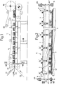
- FIG. 1 is a schematic side view of a heating device 1 for a corrugated cardboard system shown.
- a corrugated cardboard web 2 There are several, in the conveying direction of a corrugated cardboard web 2 successive heating plates 3 application, above which for example, an endless conveyor belt 4 runs over rollers 80, 81 and 82.
- the Lower strand 4.1 of this conveyor belt 4 presses against the surface of the corrugated cardboard web 2.
- the corrugated cardboard web 2 can consist of a one-sided corrugated cardboard layer 2.1, another one-sided corrugated cardboard layer 2.2 and a cover sheet 2.3 put together.
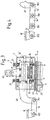
- printing units 5 are provided, which according to FIGS. 2 and 3 in one first embodiment each from a transverse to the conveying direction of the corrugated cardboard web Order 2 arranged bearings, the top of the lower strand 4.1 of the conveyor belt 4 acting pressure element 7 is attached.
- the pressure element 7 is freely movable only connected to the bearing 6 via at least one elastic medium 11. 3 as elastic Medium compression springs 11 application, which is on the one hand on the bottom of the bearing 6 and on the other hand support on the top of the pressure element 7.
- the compression springs 11 are caused by the weight of the bearing 6 loads and transmit this weight to the pressure element 7.
- a plurality of pressure elements 7 can be arranged next to one another and preferably be coupled to one another on a common bearing 6.
- FIG. 2 further shows that the bearing 6 on both sides of the corrugated cardboard web 2 in the plane of the upper side of the conveyor belt 4.1 on the machine frame 10 or articulated on side supports 47 (see FIGS. 8 and 9).
- This Linkage is shown in more detail in Fig. 3:
- the bearing 6 is laterally with a linkage lever 6.1 connected, which via a joint 13.1 to an intermediate lever 14, another joint 13.2 and a lever, not specified, e.g. is attached to the machine frame 10.
- the bearing 6 in the vertical direction by an external lifting device e.g. by pneumatic cylinder 65, i.e. by means of the cylinders 65, the pressure elements 7 can be loaded via bearings 6 and compression springs 11 or be relieved.
- FIG. 3 Possibility of two intermediate levers 14 'and 14' 'and corresponding intermediate joints 13.1, 13.2, 13.3 and 13.4.
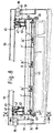
- the pressure element 7 encloses the bearing 6 and has a rectangular shape.
- the bearing 6 is between the top and bottom spring pairs 11 and 21 of the Pressure element 7 clamped.
- the springs 21 are softer "than the springs 11; they only serve to absorb the impact of this bearing against the pressure elements 7 when the bearing 6 is raised; they thus have a kind of shock absorber function.
- the bearing 6 with the pressure element 7 shock elements 24 which can be acted upon on the inside is connected.
- These bumpers 24 are preferably located near the area of the horizontal plane between the top of the lower conveyor belt 4.1 and the bottom of the pressure element 7 and are thus able to withstand frictional forces from the pressure element 7 to take over. They are advantageously close to the friction surface, to also minimize unwanted torques of the pressure element 7 or to avoid and are arranged in a plate 25 which is connected to the bearing 6 is screwed.
- the above-mentioned upper springs 21 serve the bearing 6 approximately in the middle Clamp area of the pressure element 7. These pressure elements 7 are perfect free and can lay down on the top of the lower strand 4.1.
- the chain 15 can also each in a guide 20 of the machine frame 10 be guided. From Fig. 5 it can also be seen that the Chain 15 at least one angular element which can be acted upon by a lifting element 22 23, wherein the lifting element 22 is attached to the machine frame 10 is. This makes it possible to use the lifting element 22 and the angle element 23 to raise the bearing 6 with the pressure elements 7 or functionally set against the corrugated cardboard web 2.
- a separating layer 28 which serves as thermal insulation, e.g. in the form of thermal or mineral wadding.
- Stop elements 27 are used to ensure that the entire unit functions correctly to adjust and / or secure against unwanted movement.
- the stop elements 27 have the same function as the springs 21 in FIG. 3. They can be designed as screws with an elastic pressure piece installed on the inside be.
- the impact elements 24 are arranged in a plate 25 analogously to the embodiment according to FIG. 3, which in turn is penetrated by the lower springs 11.
- This plate 25 is attached to the underside of the bearing 6 by screws.
- stop elements 27 so that also in this embodiment the pressure element 7 freely movable only via the springs 11 and the elastic Stop elements 27 is connected to the bearing 6.
- the pressure element 7, which is preferably rectangular, the bearing 6 or there are several Pressure elements 7 are provided.
- FIG. 2 there is also according to FIG Possibility that the pressure element 7 'C-shaped and horizontal over at least one elastic medium, for example the two springs 11 free is movably arranged on the underside of the bearing 6. Again one finds on the underside of the bearing 6 intermediate plate 25 'application, which the thrust elements 24 in accordance with the embodiment of FIG. 3.
- FIG. 8 From Fig. 8 it can be seen that the cross member 50 on each side via a lifting device 51, consisting of a support and e.g. an air bellows cylinder 80, on Machine frame 10 is attached.
- the lifting devices 51 offer the possibility of moving the traverses 50 around about 150 to 200 mm and thus a section with the carrier 47 e.g. 10 load units, each with three bearings 6 from the corrugated cardboard web take off and take it out of operation. This is e.g. necessary for machine stops, for cleaning purposes or for inspection of the heating surface.
- the lifting units each with a bracket 49 and one Lift cylinder 65, a single load unit with three bearings 6, which are connected to one another via two plates 43.
- This elasticity is particularly important for smaller working widths when in no corrugated cardboard runs through the outer area and the lower run 4.1 directly on the heating plate 3 rests. If you drive without a conveyor belt, you absolutely have to avoid the edge of the corrugated web with an edge of a pressure element meets so that the cardboard edge is not damaged.
- a spring leaf 73 is used, which over the entire pressure width on the inner surface of the pressure element 7 'lies.
- This spring leaf 73 is via a plate 74 and fasteners attached to the bearing 6 and in turn is acted upon by the aforementioned springs 11.
- the springs 11 press on the spring leaf 73 and not against the pressure element 7 '.
- push elements 24 ' are provided, and analogous to the aforementioned embodiments.
- This variant is also suitable especially for corrugated cardboard webs with large width differences.
- the pressure elements 7 'and Bearing 6 are attached to at least one rotating conveyor chain 57.
- the conveyor chain 57 can be moved back and forth to avoid that unwanted residues are deposited.
- the circulating conveyor chain 57 can also be equipped with pressure elements 7 'over its entire length where, e.g. indirect heating in the area of the upper run the pressure elements 7 'can be carried out.
- the pressure element 7 '' ' can be longitudinal and have transverse bores 68 and 68 ', which are elastic Hoses 71 or pipes with at least one heating medium source, not shown connected is.
- the pressure element 7 '' ' thicker than in the aforementioned embodiments, in order to accommodate to offer for the holes 68 and 68 '.
- This embodiment can be used for example in corrugated cardboard double-double to the top cover sheet of the bottom one-sided corrugated layer heat the bond with the second one-sided corrugated cardboard layer.
- a printing unit 5 consisting of bearings 6 and several Pressure elements 7 or 7 'or 7' 'or 7' '', which are a good fit guaranteed to the corrugated cardboard web 2 to be processed and no negative Exerts forces on the aforementioned path. This makes it easy achieved a significant improvement in quality.
- FIG. 22 and 23 show a top view of the movable ones Pressure elements.
- the starting position 72 of the printing elements is solid Lines shown.
- there were a few Time in the spaces 74 between the printing elements dust, paper fibers, Residues of glue and dirt.
- Another disadvantage is the uneven Frictional wear of the heating plates because the gaps 74 are not under pressure are acted on and therefore wear less.
- the beams 47 are no longer firmly connected to the crossmember 50, but via not shown, swinging intermediate lever.
- the carriers 47 are so suspended on the traverse 50.
- the entire oscillating pressure system is shown as frame 75 in FIG. 22 shown.
- a lifting system or an adjustment mechanism 76 e.g. a hydraulic or pneumatic cylinder moves the pressure system with the frame 75 in Direction 77 there and back periodically.
Landscapes
- Engineering & Computer Science (AREA)
- Mechanical Engineering (AREA)
- Machines For Manufacturing Corrugated Board In Mechanical Paper-Making Processes (AREA)
Applications Claiming Priority (2)
| Application Number | Priority Date | Filing Date | Title |
|---|---|---|---|
| DE19811858A DE19811858A1 (de) | 1998-03-18 | 1998-03-18 | Heizvorrichtung für eine Wellpappenanlage |
| DE19811858 | 1998-03-18 |
Publications (3)
| Publication Number | Publication Date |
|---|---|
| EP0943423A2 true EP0943423A2 (fr) | 1999-09-22 |
| EP0943423A3 EP0943423A3 (fr) | 2000-09-27 |
| EP0943423B1 EP0943423B1 (fr) | 2002-09-11 |
Family
ID=7861389
Family Applications (1)
| Application Number | Title | Priority Date | Filing Date |
|---|---|---|---|
| EP99103203A Expired - Lifetime EP0943423B1 (fr) | 1998-03-18 | 1999-02-18 | Dispositif de chauffage pour un système de fabrication de carton ondulé |
Country Status (3)
| Country | Link |
|---|---|
| US (1) | US6189445B1 (fr) |
| EP (1) | EP0943423B1 (fr) |
| DE (2) | DE19811858A1 (fr) |
Cited By (2)
| Publication number | Priority date | Publication date | Assignee | Title |
|---|---|---|---|---|
| EP1101599A1 (fr) * | 1999-11-15 | 2001-05-23 | BHS CORRUGATED MASCHINEN- UND ANLAGENBAU GmbH | Dispositif de chauffage pour une machine de fabrication de carton ondulé |
| US7291243B2 (en) | 2003-06-27 | 2007-11-06 | Fosber S.P.A. | Device for joining sheets of cardboard to form corrugated cardboard |
Families Citing this family (1)
| Publication number | Priority date | Publication date | Assignee | Title |
|---|---|---|---|---|
| CN108437566B (zh) * | 2018-03-21 | 2019-05-10 | 盐城君雅实业有限公司 | 一种纸板压平装置 |
Family Cites Families (6)
| Publication number | Priority date | Publication date | Assignee | Title |
|---|---|---|---|---|
| US5421951A (en) * | 1991-10-16 | 1995-06-06 | Trus Joist Macmillan | Platen press |
| IT1254506B (it) * | 1992-03-06 | 1995-09-25 | Procedimento e macchina per accoppiare elementi componenti il cartone ondulato a piu' strati | |
| US5456783A (en) * | 1993-05-06 | 1995-10-10 | Interfic Developments Incorporated | Apparatus and method for enhancing heating uniformity for setting adhesive in corrugated paperboard manufacturing |
| US5526739A (en) * | 1993-09-22 | 1996-06-18 | Corrugated Gear & Services Inc. | Apparatus for applying variable pressure to a surface |
| US5611267A (en) * | 1993-09-22 | 1997-03-18 | Corrugated Gear & Services, Inc. | Apparatus and method for applying variable pressure to a surface in corrugated paperboard manufacturing |
| US5561918A (en) * | 1995-06-26 | 1996-10-08 | Marquip, Inc. | Web holdown and drive for corrugator double backer |
-
1998
- 1998-03-18 DE DE19811858A patent/DE19811858A1/de not_active Withdrawn
-
1999
- 1999-02-18 EP EP99103203A patent/EP0943423B1/fr not_active Expired - Lifetime
- 1999-02-18 DE DE59902614T patent/DE59902614D1/de not_active Expired - Lifetime
- 1999-03-17 US US09/271,230 patent/US6189445B1/en not_active Expired - Lifetime
Cited By (2)
| Publication number | Priority date | Publication date | Assignee | Title |
|---|---|---|---|---|
| EP1101599A1 (fr) * | 1999-11-15 | 2001-05-23 | BHS CORRUGATED MASCHINEN- UND ANLAGENBAU GmbH | Dispositif de chauffage pour une machine de fabrication de carton ondulé |
| US7291243B2 (en) | 2003-06-27 | 2007-11-06 | Fosber S.P.A. | Device for joining sheets of cardboard to form corrugated cardboard |
Also Published As
| Publication number | Publication date |
|---|---|
| EP0943423B1 (fr) | 2002-09-11 |
| DE19811858A1 (de) | 1999-09-23 |
| DE59902614D1 (de) | 2002-10-17 |
| EP0943423A3 (fr) | 2000-09-27 |
| US6189445B1 (en) | 2001-02-20 |
Similar Documents
| Publication | Publication Date | Title |
|---|---|---|
| DE69404733T2 (de) | Verfahren und Vorrichtung zur Verbesserung der Gleichmässigkeit der Erwärmung eines Klebestoffes für die Herstellung von Wellpappe | |
| DE102008022857A1 (de) | Kontinuierlich arbeitende Presse zur Herstellung von Werkstoffplatten, ein Verfahren zum Betreiben derselben Presse und eine Steuer- und Regelvorrichtung für die kontinuierlich arbeitende Presse | |
| DE1957270B1 (de) | Vorrichtung zum Herstellen von Wellpappe mit doppelseitig glatter Deckbahn | |
| DE60307248T2 (de) | Vorrichtung zum Verbinden von Bogen aus Karton zur Bildung von Wellpappe | |
| EP2535158A1 (fr) | Agencement de boulons Scalper pour la mise de niveau de quantités de marchandises se trouvant sur une bande de transport, notamment quantités de marchandises en bois | |
| DE102007021200B4 (de) | Verfahren zur Verdichtung einer Pressgutmatte im Zuge der Herstellung von Werkstoffplatten und eine kontinuierlich arbeitende Presse | |
| DE2108378A1 (de) | Vorrichtung zum Herstellen von Wellpappe mit doppelseitig glatter Bahn | |
| DE69616659T2 (de) | Anpressvorrichtung für eine Vorrichtung zur Herstellung von Wellpappen | |
| DE3436158C2 (fr) | ||
| DE102006062627A1 (de) | Vorpresse zur Vorverdichtung und Entlüftung einer Pressgutmatte im Zuge der Herstellung von Werkstoffplatten | |
| DE19601379C2 (de) | Vorrichtung zum Andrücken eines umlaufenden Schleifbandes an die Oberfläche eines Werkstücks | |
| EP0943423B1 (fr) | Dispositif de chauffage pour un système de fabrication de carton ondulé | |
| CH627720A5 (de) | Einrichtung zur herstellung einer isolierglasscheibe und verwendung derselben. | |
| CH652075A5 (de) | Einseitenkaschierer. | |
| EP0458806B1 (fr) | Procede et installation de production de panneaux d'agglomeres en bois et de materiaux similaires pour panneaux | |
| DE4010308C2 (de) | Kontinuierlich arbeitende Presse | |
| DE19622204A1 (de) | Kontinuierlich arbeitende Presse | |
| EP0344192B1 (fr) | Procede et installation de fabrication de panneaux en copeaux de bois et materiaux similaires | |
| CH666300A5 (de) | Vorrichtung zum fuehren der siebe einer doppelsiebpartie einer papier- oder kartonmaschine. | |
| DE60114735T2 (de) | Reinigungsvorrichtung zur wahlweisen Reinigung von zwei oder mehreren Zylindern in einer Druckmaschine, mit einer einzigen Reinigungsvorrichtung | |
| CH620006A5 (fr) | ||
| DE19904451A1 (de) | Kalander für bahnförmige Materialien wie Papier | |
| DE60033124T2 (de) | Entwässerungsleiste für eine Papiermaschine | |
| CH659420A5 (de) | Bandschleifmaschine fuer spanplatten. | |
| DE102005053920B4 (de) | Verfahren zum Einstellen eines Einlaufkeilverdichters einer kontinuierlich arbeitenden Presse im Zuge der Herstellung von Werkstoffplatten und eine kontinuierlich arbeitende Presse zur Durchführung des Verfahrens |
Legal Events
| Date | Code | Title | Description |
|---|---|---|---|
| PUAI | Public reference made under article 153(3) epc to a published international application that has entered the european phase |
Free format text: ORIGINAL CODE: 0009012 |
|
| AK | Designated contracting states |
Kind code of ref document: A2 Designated state(s): DE FR GB IT |
|
| AX | Request for extension of the european patent |
Free format text: AL;LT;LV;MK;RO;SI |
|
| PUAL | Search report despatched |
Free format text: ORIGINAL CODE: 0009013 |
|
| AK | Designated contracting states |
Kind code of ref document: A3 Designated state(s): AT BE CH CY DE DK ES FI FR GB GR IE IT LI LU MC NL PT SE |
|
| AX | Request for extension of the european patent |
Free format text: AL;LT;LV;MK;RO;SI |
|
| 17P | Request for examination filed |
Effective date: 20000922 |
|
| AKX | Designation fees paid |
Free format text: DE FR GB IT |
|
| GRAG | Despatch of communication of intention to grant |
Free format text: ORIGINAL CODE: EPIDOS AGRA |
|
| 17Q | First examination report despatched |
Effective date: 20020204 |
|
| GRAG | Despatch of communication of intention to grant |
Free format text: ORIGINAL CODE: EPIDOS AGRA |
|
| GRAH | Despatch of communication of intention to grant a patent |
Free format text: ORIGINAL CODE: EPIDOS IGRA |
|
| GRAH | Despatch of communication of intention to grant a patent |
Free format text: ORIGINAL CODE: EPIDOS IGRA |
|
| GRAA | (expected) grant |
Free format text: ORIGINAL CODE: 0009210 |
|
| AK | Designated contracting states |
Kind code of ref document: B1 Designated state(s): DE FR GB IT |
|
| REG | Reference to a national code |
Ref country code: GB Ref legal event code: FG4D Free format text: NOT ENGLISH |
|
| REF | Corresponds to: |
Ref document number: 59902614 Country of ref document: DE Date of ref document: 20021017 |
|
| GBT | Gb: translation of ep patent filed (gb section 77(6)(a)/1977) |
Effective date: 20021107 |
|
| ET | Fr: translation filed | ||
| PLBE | No opposition filed within time limit |
Free format text: ORIGINAL CODE: 0009261 |
|
| STAA | Information on the status of an ep patent application or granted ep patent |
Free format text: STATUS: NO OPPOSITION FILED WITHIN TIME LIMIT |
|
| 26N | No opposition filed |
Effective date: 20030612 |
|
| PGFP | Annual fee paid to national office [announced via postgrant information from national office to epo] |
Ref country code: IT Payment date: 20120224 Year of fee payment: 14 |
|
| PG25 | Lapsed in a contracting state [announced via postgrant information from national office to epo] |
Ref country code: IT Free format text: LAPSE BECAUSE OF NON-PAYMENT OF DUE FEES Effective date: 20130218 |
|
| PGFP | Annual fee paid to national office [announced via postgrant information from national office to epo] |
Ref country code: GB Payment date: 20150223 Year of fee payment: 17 |
|
| REG | Reference to a national code |
Ref country code: FR Ref legal event code: PLFP Year of fee payment: 18 |
|
| PGFP | Annual fee paid to national office [announced via postgrant information from national office to epo] |
Ref country code: FR Payment date: 20160222 Year of fee payment: 18 |
|
| PGFP | Annual fee paid to national office [announced via postgrant information from national office to epo] |
Ref country code: DE Payment date: 20160422 Year of fee payment: 18 |
|
| GBPC | Gb: european patent ceased through non-payment of renewal fee |
Effective date: 20160218 |
|
| PG25 | Lapsed in a contracting state [announced via postgrant information from national office to epo] |
Ref country code: GB Free format text: LAPSE BECAUSE OF NON-PAYMENT OF DUE FEES Effective date: 20160218 |
|
| REG | Reference to a national code |
Ref country code: DE Ref legal event code: R119 Ref document number: 59902614 Country of ref document: DE |
|
| REG | Reference to a national code |
Ref country code: FR Ref legal event code: ST Effective date: 20171031 |
|
| PG25 | Lapsed in a contracting state [announced via postgrant information from national office to epo] |
Ref country code: FR Free format text: LAPSE BECAUSE OF NON-PAYMENT OF DUE FEES Effective date: 20170228 Ref country code: DE Free format text: LAPSE BECAUSE OF NON-PAYMENT OF DUE FEES Effective date: 20170901 |