EP0943441B1 - Tete d'enregistrement a jet d'encre et enregistreur a jet d'encre - Google Patents
Tete d'enregistrement a jet d'encre et enregistreur a jet d'encre Download PDFInfo
- Publication number
- EP0943441B1 EP0943441B1 EP98923099A EP98923099A EP0943441B1 EP 0943441 B1 EP0943441 B1 EP 0943441B1 EP 98923099 A EP98923099 A EP 98923099A EP 98923099 A EP98923099 A EP 98923099A EP 0943441 B1 EP0943441 B1 EP 0943441B1
- Authority
- EP
- European Patent Office
- Prior art keywords
- ink
- jet recording
- recording apparatus
- nozzle
- blade
- Prior art date
- Legal status (The legal status is an assumption and is not a legal conclusion. Google has not performed a legal analysis and makes no representation as to the accuracy of the status listed.)
- Expired - Lifetime
Links
- 239000011241 protective layer Substances 0.000 claims description 75
- 239000010410 layer Substances 0.000 claims description 21
- 239000005871 repellent Substances 0.000 claims description 21
- 238000004140 cleaning Methods 0.000 claims description 19
- 239000000428 dust Substances 0.000 claims description 14
- 230000001105 regulatory effect Effects 0.000 claims description 6
- 238000010030 laminating Methods 0.000 claims description 2
- 238000010438 heat treatment Methods 0.000 claims 1
- 238000007639 printing Methods 0.000 description 7
- PXHVJJICTQNCMI-UHFFFAOYSA-N Nickel Chemical compound [Ni] PXHVJJICTQNCMI-UHFFFAOYSA-N 0.000 description 2
- 230000000694 effects Effects 0.000 description 2
- 238000005323 electroforming Methods 0.000 description 2
- 238000009713 electroplating Methods 0.000 description 2
- 238000005530 etching Methods 0.000 description 2
- 239000000463 material Substances 0.000 description 2
- 239000007769 metal material Substances 0.000 description 2
- 238000000638 solvent extraction Methods 0.000 description 2
- 239000000758 substrate Substances 0.000 description 2
- 239000011248 coating agent Substances 0.000 description 1
- 238000000576 coating method Methods 0.000 description 1
- 238000006073 displacement reaction Methods 0.000 description 1
- 230000005489 elastic deformation Effects 0.000 description 1
- 238000007772 electroless plating Methods 0.000 description 1
- 229920002313 fluoropolymer Polymers 0.000 description 1
- 239000004811 fluoropolymer Substances 0.000 description 1
- 238000011010 flushing procedure Methods 0.000 description 1
- 238000007641 inkjet printing Methods 0.000 description 1
- 239000002184 metal Substances 0.000 description 1
- 229910052751 metal Inorganic materials 0.000 description 1
- 229910052759 nickel Inorganic materials 0.000 description 1
- 239000007787 solid Substances 0.000 description 1
- 125000006850 spacer group Chemical group 0.000 description 1
- 238000004544 sputter deposition Methods 0.000 description 1
- 238000011144 upstream manufacturing Methods 0.000 description 1
Images








Classifications
-
- B—PERFORMING OPERATIONS; TRANSPORTING
- B41—PRINTING; LINING MACHINES; TYPEWRITERS; STAMPS
- B41J—TYPEWRITERS; SELECTIVE PRINTING MECHANISMS, i.e. MECHANISMS PRINTING OTHERWISE THAN FROM A FORME; CORRECTION OF TYPOGRAPHICAL ERRORS
- B41J2/00—Typewriters or selective printing mechanisms characterised by the printing or marking process for which they are designed
- B41J2/005—Typewriters or selective printing mechanisms characterised by the printing or marking process for which they are designed characterised by bringing liquid or particles selectively into contact with a printing material
- B41J2/01—Ink jet
- B41J2/135—Nozzles
- B41J2/14—Structure thereof only for on-demand ink jet heads
- B41J2/1433—Structure of nozzle plates
-
- B—PERFORMING OPERATIONS; TRANSPORTING
- B41—PRINTING; LINING MACHINES; TYPEWRITERS; STAMPS
- B41J—TYPEWRITERS; SELECTIVE PRINTING MECHANISMS, i.e. MECHANISMS PRINTING OTHERWISE THAN FROM A FORME; CORRECTION OF TYPOGRAPHICAL ERRORS
- B41J2/00—Typewriters or selective printing mechanisms characterised by the printing or marking process for which they are designed
- B41J2/005—Typewriters or selective printing mechanisms characterised by the printing or marking process for which they are designed characterised by bringing liquid or particles selectively into contact with a printing material
- B41J2/01—Ink jet
- B41J2/135—Nozzles
- B41J2/16—Production of nozzles
- B41J2/1606—Coating the nozzle area or the ink chamber
-
- B—PERFORMING OPERATIONS; TRANSPORTING
- B41—PRINTING; LINING MACHINES; TYPEWRITERS; STAMPS
- B41J—TYPEWRITERS; SELECTIVE PRINTING MECHANISMS, i.e. MECHANISMS PRINTING OTHERWISE THAN FROM A FORME; CORRECTION OF TYPOGRAPHICAL ERRORS
- B41J2/00—Typewriters or selective printing mechanisms characterised by the printing or marking process for which they are designed
- B41J2/005—Typewriters or selective printing mechanisms characterised by the printing or marking process for which they are designed characterised by bringing liquid or particles selectively into contact with a printing material
- B41J2/01—Ink jet
- B41J2/135—Nozzles
- B41J2/165—Prevention or detection of nozzle clogging, e.g. cleaning, capping or moistening for nozzles
- B41J2/16517—Cleaning of print head nozzles
- B41J2/16535—Cleaning of print head nozzles using wiping constructions
- B41J2/16538—Cleaning of print head nozzles using wiping constructions with brushes or wiper blades perpendicular to the nozzle plate
Definitions
- the present invention relates to an ink-jet recording head for jetting ink pressurized in a pressure generating chamber by pressurizing means from a nozzle aperture as an ink droplet, and in more detail, relates to an ink-jet recording head in which a nozzle aperture can be prevented from being clogged by a wiping member.
- An ink-jet recording head is provided with a nozzle plate wherein nozzle apertures are made at predetermined pitch in a thin plate, a pressure generating chamber communicating with each nozzle aperture and a reservoir for supplying ink to a pressure generating chamber as well-known, and is constituted so that an ink droplet is jetted from a nozzle aperture by pressurizing ink in a pressure generating chamber by a piezoelectric vibrator, a heater element and others.
- a measure to prevent recording paper from coming in contact with a protective layer in the vicinity of each nozzle aperture N by forming the protective layer composed of a metallic layer 1 to 30 ⁇ m thick in an area apart by approximately 100 to 150 ⁇ m from each nozzle aperture N of a nozzle plate P so that a concave portion C is formed around each nozzle aperture N is taken. See for instance JP-A-08 025 630.
- a concave portion C between adjacent nozzle apertures in the same column is extremely small to form an independent concave portion C every nozzle aperture as described above in case recently, pitch at which nozzle apertures are arranged is 180 dpi per column and extremely small to enhance printing quality, it is very difficult to form such a concave portion. Therefore, as shown in Fig. 21B, a rectangular common concave portion C' is formed around nozzle apertures N in one column.
- a recording head H provided with the nozzle plate P constituted as described above is relatively moved in the direction D or D' of a blade B as shown as II and II' after the blade B is lifted on the side of the recording head H with the recording head located on the upstream side of the blade B arranged on a path of movement as shown in Fig. 22 (I) which is cleaning means, hereby, the blade B is elastically touched to the recording head H as shown as III and III' and hereby, cleaning is executed.
- An ink-jet recording head comprises plural pressure generating chambers arranged at predetermined pitch linearly in one or more columns for pressurizing ink by pressurizing means and a nozzle plate in which plural nozzle apertures each of which communicates with each pressure generating chamber are formed and a protective layer for regulating so that a part of a blade comes in contact with a nozzle aperture when the blade is pressed on the nozzle plate is formed in the vicinity of the above nozzle aperture in a state in which an open exhaust port is secured on the side of the end of the protective layer in a direction in which the blade for cleaning is moved.
- a first object of the present invention is to provide an ink-jet recording head wherein ink which adheres to the nozzle plate, the leavings of ink and dust on paper can be securely exhausted in an area which has no effect upon jetting an ink droplet without wearing an ink-repellent layer and further, the ink-repellent layer can be prevented from being worn or broken by contact between the ink-repellent layer and recording paper.
- a second object of the present invention is to provide an ink-jet recording apparatus provided with cleaning means suitable for the above recording head.
- Fig. 1 shows an embodiment of a recording apparatus using an ink-jet recording head according to the present invention
- a carriage 1 is connected to a pulse motor 3 via a timing belt 2, the carriage is constituted so that it is guided by a guide member 4 and reciprocated in the direction of the width of recording paper 5 and ink-jet recording heads 6 and 7 described later are attached to the surface opposite to the recording paper 5, the lower surface in this embodiment.
- the ink-jet recording heads 6 and 7 are respectively supplied with ink by ink cartridges 8 and 9 mounted on the carriage 1, respectively jet an ink droplet on the recording paper 5 as the carriage 1 is moved, respectively form one or plural dots per one pixel and respectively print images and characters on the recording paper 5.
- a capping device 10 is provided in a non-printing area, seals nozzle apertures of the recording heads 6 and 7 during rest to prevent the nozzle apertures from being dry and in the meantime, also functions as a receptacle for receiving an ink droplet jetted from the recording heads 6 and 7 by flushing operation executed during printing.
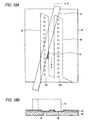
- a cleaning device 11 is provided in the vicinity of the capping device in the non-printing area and arranged so that a blade 12 for touching the nozzle plates of the recording heads 6 and 7 as shown in Figs. 2 has a gradient of an angle ⁇ with a direction perpendicular to a direction in which nozzle apertures are arranged, that is, a direction in which the carriage 1 is moved.
- Fig. 3 shows an embodiment of the above recording head and pressure generating means, a piezoelectric vibrator 13 in this embodiment and a passage unit 14 to which displacement from the above piezoelectric vibrator is applied are fixed to a holder 15.
- the passage unit 14 is constituted by laminating an elastic plate 16 which is in contact with the end of the piezoelectric vibrator 13 and to which elastic deformation is applied, a spacer 20 partitioning a pressure generating chamber 17, an ink supply port 18 and a reservoir 19, and a nozzle plate 22 provided with a nozzle aperture 21 communicating with the pressure generating chamber 17.
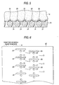
- the nozzle plate 22 is provided with two columns of nozzle apertures 21 each of which is formed at predetermined pitch as shown in Figs. 4, and long and narrow protective layers 23 extended in parallel with a wiping direction at the same pitch as pitch between adjacent nozzle apertures 21 so that at least the protective layer is opposite to the nozzle aperture 21 are discretely formed in each column of nozzle apertures 21.
- the height H of the protective layer 23 is set to approximately 2 to 10 ⁇ m and is formed so that the length L is at least larger than the diameter d of the nozzle aperture 21.
- These protective layers 23 can be formed by etching a substrate to be the nozzle plate 23, electroforming metallic material on the nozzle plate 22 in a shape equivalent to the protective layer 23 or sticking a thin piece formed beforehand as another member.
- the protective layer 23 is formed at the same pitch as pitch between adjacent nozzle apertures, however, one protective layer 23 per plural nozzle apertures 21 may be also formed as shown in Fig. 6.
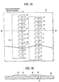
- Figs. 7A and 7B respectively show a second embodiment of the present invention and in this embodiment, a band 24 is formed by connecting the side of the admission port of a blade 12 of each protective layer 23 so that the downstream side of each protective layer 23 in a direction in which the blade 12 is moved is open.
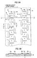
- a direction perpendicular to a direction in which nozzle apertures 21 are arranged is a horizontal direction, however, as shown in Fig. 8, if the protective layer 23 is tilted by the approximately similar angle ⁇ ' in case the blade 12 is tilted by an angle ⁇ with a direction in which nozzle apertures are arranged, the leavings of ink, dust on paper and ink can be efficiently exhausted into an area not related to jetting an ink droplet without reducing rejection ratio.
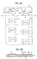
- Figs. 9 show the structure of a nozzle plate equivalent to further another embodiment of the present invention, a protective layer 30 is formed between nozzle apertures 21 formed at predetermined pitch in a nozzle plate 22.
- the protective layer 30 comprises the body 30a parallel to a direction in which recording heads 6 and 7 are moved and a wider branch 30b than the width of the body which is perpendicular to the direction in which the recording heads 6 and 7 are moved and in the center of which the end of the body 30a is located.
- the height H of the protective layer 30 is set to approximately 2 to 10 ⁇ m, and the body 30a and the branch 30b are formed so that each length La and Lb is at least larger than the diameter of the nozzle aperture 21.
- These protective layers 30 are arranged at predetermined pitch, at the same pitch as the nozzle aperture 21 in this embodiment so that an interval Lc is made between the end of the body 30a and the branch 30b of adjacent protective layers 30 to open at least a direction in which a blade 12 is moved.
- These protective layers 30 can be readily formed by etching a substrate to be the nozzle plate 22 in a desired shape, forming them on the nozzle plate 22 by electroforming metallic material such as nickel in a shape equivalent to the protective layer 30 or forming a thin piece in a shape equivalent to the protective layer as another member and bonding the thin piece to the nozzle plate 22 as in the case of the above protective layer 23.
- a reference number 31 denotes an ink-repellent layer and the ink-repellent layer is formed by coating or electrolytic plating ink-repellent material a few hundred nm to a few ⁇ m thick formed around the nozzle aperture 21 such as fluoropolymers.
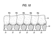
- the end of the wiper blade 12 when the end of the wiper blade 12 is touched to the nozzle plate 22 and wiping is executed, the end of the blade 12 elastically comes in contact with a part between the bodies 30a of the protective layers 30 as shown in Fig. 10 when the blade passes the nozzle aperture 21.
- the wiper blade 12 is relatively moved in the axial direction of the body 30a in this state, the leavings of ink and dust on paper in the vicinity of the nozzle aperture 21 are removed, preventing the ink-repellent layer 31 from being worn or deteriorated because the ink-repellent layer 31 formed around the nozzle aperture 21 is never rubbed with strong contact force.
- Ink and dust on paper at the nozzle aperture 21 and in the vicinity which are wiped by the wiper blade 12 as described above are swept in an area not related to jetting an ink droplet from an exhaust port located on the downstream side of the adjacent protective layers 30 and never remain around the nozzle aperture 21.
- Ink and dust on paper which are rubbed by the branch 30b of the protective layer 30 and adhere to another branch 30b are flushed when the recording heads 6 and 7 are sealed by a capping device 10 and ink is forcedly exhausted from the recording heads 6 and 7 by a suction pump 16.
- recording paper can be securely prevented from coming in contact with the ink-repellent layer 31 in the vicinity of the nozzle aperture 21 due to a paper jam, or the like.
- Figs. 11 show furthermore another embodiment of the present invention and in this embodiment, the branch 30b' of a protective layer 30 is extended so that it is twice or more as long as pitch between adjacent nozzle apertures 21 and the bodies 30a are arranged at an interval twice or more as long as pitch between adjacent nozzle apertures 21.
- the refresh rate of the wiper blade 12 is enhanced by quantity in which the length of the branch 30b is longer than that in the above embodiment shown in Figs. 9.
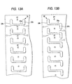
- a protective layer 30 is constituted so that branches 30b longer than pitch between adjacent nozzle apertures 21 are formed at both ends of the body 30a with the body located in the center of the protective layer 30 and the protective layers are arranged at pitch twice as long as the pitch between adjacent nozzle apertures 21 in each column so that they are zigzag.
- the body and the branch are arranged so that they are in the shape of a letter H, however, the similar action is produced even if as shown in Fig. 13A, the body 30a is arranged so that it is located between nozzle apertures and branches 30b are arranged on the same side, on the upper side in Fig. 13A in this embodiment so that an interval can be formed between the bodies 30a of adjacent protective layers 30 and as shown in Fig. 13B, the branches 30b are formed in reverse directions in the shape of a key.
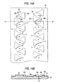
- Figs. 14 show furthermore another embodiment of the present invention and a protective layer 35 is formed approximately in the shape of a triangle symmetrical in a direction in which a linear part 35a which is approximately perpendicular to a path on which the blade is moved on the side opposite to a direction in which the blade 12 is moved and which is longer than pitch between adjacent nozzle apertures 21 and a curved part 35b forming a vertex 35b tapered from the linear part to the side of the nozzle aperture on the side opposite to the nozzle aperture 21 are perpendicular to a direction in which nozzle apertures are arranged.
- Pitch between the adjacent protective layers 35 is equal to pitch between the adjacent nozzle apertures 21 and the protective layers are arranged with them alternately inverted so that the side of the vertex is located on the side of the nozzle aperture.
- Figs. 15 show furthermore another embodiment of the present invention and a protective layer 36 is formed so that a linear part 36a which is approximately perpendicular to a path on which a blade is moved on the side opposite to a direction in which the blade 12 is moved and which is longer than pitch between adjacent nozzle apertures 21 and a curved part the center of which is the narrowest part are both symmetrical in a direction in which the nozzle apertures are arranged and a direction perpendicular to the direction.
- These protective layers 36 are arranged at pitch twice as long as pitch between adjacent nozzle apertures 21 so that the narrowest part is opposite to the nozzle aperture.
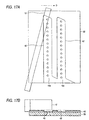
- Figs. 16 show the structure of a nozzle plate equivalent to furthermore another embodiment of the present invention and rectangular concave portions 40 and 40' respectively surrounding nozzle apertures 21 and nozzle apertures 21' in the respective columns and provided with open parts 40a and 40a' at the end of a nozzle plate 22 (the lower end in Fig. 16A) are formed. These concave portions 40 and 40' are connected by a concave portion 41 formed in a boundary between them.
- concave portions 40 and 40' and the concave portion 41 are constituted by providing a protective layer 43 made of metal and others with the thickness of approximately 5 to 30 ⁇ m by sputtering, electroless plating, electrolytic plating and others and an ink-repellent layer 44 is formed by material provided with ink repellency inside at least the concave portions 40 and 407.
- the recording paper as recording paper is supported by the surface of the protective layer 43 in case the recording paper comes in contact with the surface of the nozzle plate 22 in printing, the recording paper crosses the concave portions 40 and 40', does not come in contact with the ink-repellent layer 44 which has a great effect upon ink jetting performance in the concave portions 40 and 40' and therefore, does not peel the ink-repellent layer.
- the blade 12 has an angle ⁇ with a direction in which nozzle apertures 21 are arranged when the blade 12 is elastically touched to the nozzle plates 22 of recording heads 6 and 7 and the blade 12 or the recording head 6 is relatively moved in a direction shown by an arrow D in Fig. 17 if cleaning is required because of long-time printing, the most of the blade 12 is supported by the surface of the protective layer 43, only a part enters the concave portions 40 and 40' and is elastically touched to the ink-repellent layer 44 with light force as shown in Fig. 17.
- the leavings K of ink are gathered on a wall on the downstream side of the concave portion 40 and as the blade 12 is moved, the leavings of ink are moved in a direction shown by an arrow E in Fig. 18, that is, on the side of the open port 40a as shown in Fig. 18.
- the leavings of ink are exhausted out of the nozzle plate 22 via the open port 40a.
- the leavings K of ink are also gathered on a wall on the downstream side, are moved to the open port 40a' of the concave portion 40' as described above as shown in Fig. 19, are guided to outside along the slope of the wall 40c' regulating the end of the concave portion 40' and are exhausted as shown in Fig. 20.
- the leavings K' of ink can be guided in an area not related to jetting an ink droplet, further, if the blade is extended up to the end of the nozzle plate 22, the leavings of ink can be exhausted in an area with which the blade 12 is not in contact and the leavings of ink can be prevented from adhering to the blade 12 again in cleaning.
- the ink-jet recording head of a type that a pressure generating chamber is pressurized by a piezoelectric vibrator is described as an example, however, it is clear that the similar action can be produced even if the present invention is applied to a nozzle plate of a bubble-jet recording head wherein a heater element is sealed in a pressure generating chamber and ink is jetted by thermal energy.
- the present invention if recording paper comes in contact with the nozzle plate, it can be prevented from coming in contact with the ink-repellent layer in an area in the vicinity of a nozzle aperture owing to the protective layer, in cleaning the ink-repellent layer is prevented from being worn by regulating an area with which the blade comes in contact by the protective layer and elastically touching the blade with light force enough to clean the face of an nozzle aperture and further, ink, the leavings of ink and dust on paper respectively gathered by the blade can be exhausted in an area not related to jetting an ink droplet via the open port.
Landscapes
- Engineering & Computer Science (AREA)
- Manufacturing & Machinery (AREA)
- Ink Jet (AREA)
- Particle Formation And Scattering Control In Inkjet Printers (AREA)
Claims (31)
- Appareil, comprenant :dans lequel ladite lame de nettoyage (12) est amenée à toucher élastiquement ladite plaque à buses (22) sur un trajet sur lequel ladite tête d'impression (6, 7) est déplacée lors du nettoyage, et ladite lame (12) est pressée contre ladite plaque à buses (22) de telle façon que ladite lame (12) et ladite tête d'impression (6, 7) se déplacent relativement l'une à l'autre dans une direction de déplacement (D) ;une lame (12) pour le nettoyage, constituée par un élément élastique ;une tête d'impression à jet d'encre (6, 7), comprenant :une pluralité de chambres de génération de pression (17) agencées à un pas prédéterminé suivant une ou plusieurs colonnes, pour mettre l'encre sous pression par des moyens de mise sous pression (13) ;une plaque à buses (22) dans laquelle sont formées une pluralité d'ouvertures de buses (21), dont chacune communique avec l'une desdites chambres de génération de pression (17) ; etune couche protectrice (23 ; 30 ; 35) formée au voisinage desdites ouvertures de buses (21) et adaptée à réguler le contact de ladite lame de nettoyage (12) avec lesdites ouvertures de buses (21),
caractérisé en ce que :ladite couche protectrice (23 ; 30 ; 35) comprend des ouvertures de dégagement (O) de sorte que des restes d'encre et de poussières au niveau des ouvertures de buses (21) et à leur voisinage sont balayés par la lame de nettoyage (12) à travers lesdites ouvertures de dégagement (O) jusque dans une zone (15a, 16a ; 40a, 40a') qui n'est pas concernée par la projection de gouttelettes d'encre, ladite zone (15a, 16a ; 40a, 40a') étant située sur le côté aval des couches protectrices adjacentes (23 ; 30 ; 35) par rapport à la direction de mouvement (D) de la lame de nettoyage ou la direction de mouvement (E) des restes d'encre. - Appareil d'impression à jet d'encre selon la revendication 1, dans lequel lesdits moyens de mise sous pression sont constitués par un vibrateur piézoélectrique ou par des moyens de chauffage prévus dans ladite chambre de génération de pression.
- Appareil d'impression à jet d'encre selon la revendication 1, dans lequel une couche répulsive vis-à-vis de l'encre est formée au moins au voisinage de ladite ouverture de buse.
- Appareil d'impression à jet d'encre selon la revendication 1, dans lequel ladite couche protectrice a une épaisseur de 2 à 30 µm.
- Appareil d'impression à jet d'encre selon la revendication 1, dans lequel ladite couche protectrice est formée par des moyens pour former un film sur ladite plaque à buses.
- Appareil d'impression à jet d'encre selon la revendication 1, dans lequel ladite couche protectrice est formée en laminant un autre élément.
- Appareil d'impression à jet d'encre selon la revendication 1, dans lequel ladite couche protectrice est formée de façon discrète et approximativement parallèlement à un trajet sur lequel la lame est déplacée, et entre lesdites ouvertures de buses, à un pas plus long que le pas entre des ouvertures de buses adjacentes.
- Appareil d'impression à jet d'encre selon la revendication 7, dans lequel ladite couche protectrice est formée de telle manière qu'elle est plus longue qu'un diamètre de ladite ouverture de buses.
- Appareil d'impression à jet d'encre selon la revendication 7, dans lequel lesdites couches protectrices sont agencées au moins sur un côté de ladite ouverture de buses.
- Appareil d'impression à jet d'encre selon la revendication 7, dans lequel une ramification (30b) de ladite couche protectrice perpendiculaire audit trajet suivant lequel la lame est déplacée est formée à au moins une extrémité de ladite couche protectrice.
- Appareil d'impression à jet d'encre selon la revendication 10, dans lequel ladite ramification est formée de telle manière qu'elle est au moins plus longue que le pas entre des ouvertures de buses adjacentes.
- Appareil d'impression à jet d'encre selon la revendication 10, dans lequel ladite ramification est formée de telle manière qu'elle est plus large qu'une largeur de ladite couche protectrice.
- Appareil d'impression à jet d'encre selon la revendication 10, dans lequel un jeu hors duquel l'encre peut être évacuée est défini entre ladite ramification et une autre couche protectrice adjacente.
- Appareil d'impression à jet d'encre selon la revendication 10, dans lequel lesdites ramifications (30b) sont agencées avec ladite ramification (30b) placée entre lesdites couches protectrices adjacentes (23).
- Appareil d'impression à jet d'encre selon la revendication 10, dans lequel lesdites ramifications sont formées sur le même côté aux deux extrémités de ladite couche protectrice.
- Appareil d'impression à jet d'encre selon la revendication 10, dans lequel lesdites ramifications sont formées sur des côtés opposés aux deux extrémités de ladite couche protectrice.
- Appareil d'impression à jet d'encre selon la revendication 7, dans lequel ladite couche protectrice est pourvue d'une partie linéaire (35a, 36a) approximativement perpendiculaire audit trajet sur lequel ladite lame est déplacée et d'un côté opposé à une direction dans laquelle ladite lame est déplacée, et plus longue que le pas entre des ouvertures de buses adjacentes, et d'une partie incurvée (36c, 36b) sur un côté opposé à ladite ouverture de buse.
- Appareil d'impression à jet d'encre selon la revendication 17, dans lequel ladite couche protectrice est pourvue d'un sommet (35b) effilé depuis ladite partie linéaire (35a).
- Appareil d'impression à jet d'encre selon la revendication 18, dans lequel lesdites couches protectrices sont agencées de telle façon que lesdits sommets sont opposés.
- Appareil d'impression à jet d'encre selon la revendication 18, dans lequel lesdites couches protectrices sont symétriques dans une direction perpendiculaire à une direction dans laquelle lesdites ouvertures de buses sont agencées.
- Appareil d'impression à jet d'encre selon la revendication 19, dans lequel lesdites couches protectrices sont agencées au même pas que le pas entre des ouvertures de buses adjacentes.
- Appareil d'impression à jet d'encre selon la revendication 17, dans lequel ladite couche protectrice est formée de manière que son centre est le plus étroit.
- Appareil d'impression à jet d'encre selon la revendication 22, dans lequel lesdites couches protectrices sont symétriques à la fois dans une direction dans laquelle lesdites ouvertures de buses sont agencées et dans une direction perpendiculaire à ladite direction.
- Appareil d'impression à jet d'encre selon la revendication 22, dans lequel lesdites couches protectrices sont agencées de telle façon que ladite partie la plus étroite est à l'opposé de ladite ouverture de buse.
- Appareil d'impression à jet d'encre selon la revendication 21, dans lequel lesdites couches protectrices sont agencées à un pas deux fois aussi long que le pas entre des ouvertures de buses adjacentes.
- Appareil d'impression à jet d'encre selon la revendication 7, dans lequel ladite couche protectrice entoure toutes lesdites ouvertures de buses dans la même colonne ; et une portion concave (40) pourvue d'un orifice ouvert (40a) est formée à une extrémité sur un côté aval dans une direction dans laquelle ladite lame est déplacée.
- Appareil d'impression à jet d'encre selon la revendication 26, dans lequel une paroi (41a) pour réguler un orifice ouvert (40a) de ladite portion concave est inclinée dans une direction dans laquelle ladite lame évacue.
- Appareil d'impression à jet d'encre selon la revendication 26, dans lequel une frontière entre lesdites portions concaves adjacentes est connectée par une paroi (41a) inclinée dans une direction dans laquelle ladite lame évacue.
- Appareil d'impression à jet d'encre selon la revendication 26, dans lequel ledit orifice ouvert est formé à l'extérieur de ladite ouverture de buse située à au moins une extrémité de la plaque à buses.
- Appareil d'impression à jet d'encre selon la revendication 26, dans lequel ledit orifice ouvert est formé à une extrémité de ladite plaque à buses.
- Appareil d'impression à jet d'encre selon l'une des revendications précédentes, dans lequel ladite lame est pourvue d'un gradient par rapport à une perpendiculaire audit trajet sur lequel ladite lame est déplacée.
Applications Claiming Priority (7)
| Application Number | Priority Date | Filing Date | Title |
|---|---|---|---|
| JP16185397 | 1997-06-04 | ||
| JP16185397 | 1997-06-04 | ||
| JP15877897 | 1997-06-16 | ||
| JP15877897 | 1997-06-16 | ||
| JP18759197 | 1997-06-27 | ||
| JP18759197 | 1997-06-27 | ||
| PCT/JP1998/002448 WO1998055317A1 (fr) | 1997-06-04 | 1998-06-03 | Tete d'enregistrement a jet d'encre et enregistreur a jet d'encre |
Publications (3)
| Publication Number | Publication Date |
|---|---|
| EP0943441A1 EP0943441A1 (fr) | 1999-09-22 |
| EP0943441A4 EP0943441A4 (fr) | 2000-08-23 |
| EP0943441B1 true EP0943441B1 (fr) | 2005-10-26 |
Family
ID=27321401
Family Applications (1)
| Application Number | Title | Priority Date | Filing Date |
|---|---|---|---|
| EP98923099A Expired - Lifetime EP0943441B1 (fr) | 1997-06-04 | 1998-06-03 | Tete d'enregistrement a jet d'encre et enregistreur a jet d'encre |
Country Status (5)
| Country | Link |
|---|---|
| US (1) | US6270191B1 (fr) |
| EP (1) | EP0943441B1 (fr) |
| JP (1) | JP3682488B2 (fr) |
| DE (1) | DE69832039T2 (fr) |
| WO (1) | WO1998055317A1 (fr) |
Families Citing this family (21)
| Publication number | Priority date | Publication date | Assignee | Title |
|---|---|---|---|---|
| JP3501083B2 (ja) * | 2000-03-21 | 2004-02-23 | 富士ゼロックス株式会社 | インクジェット記録ヘッド用ノズルおよびその製造方法 |
| US6412908B2 (en) | 2000-05-23 | 2002-07-02 | Silverbrook Research Pty Ltd | Inkjet collimator |
| AUPR277701A0 (en) * | 2001-01-30 | 2001-02-22 | Silverbrook Research Pty. Ltd. | An apparatus (art98) |
| JP4890693B2 (ja) * | 2001-08-10 | 2012-03-07 | キヤノン株式会社 | インクジェット記録装置 |
| US6820963B2 (en) * | 2001-12-13 | 2004-11-23 | Hewlett-Packard Development Company, L.P. | Fluid ejection head |
| EP1706269B1 (fr) * | 2003-12-30 | 2012-06-13 | Dimatix, Inc. | Dispositif d'ejection de gouttes |
| JP4781638B2 (ja) * | 2004-05-07 | 2011-09-28 | パナソニック株式会社 | インクジェット記録装置のラインヘッドワイピング方法 |
| JP5266624B2 (ja) * | 2005-05-17 | 2013-08-21 | ブラザー工業株式会社 | 液滴噴射装置及び液滴噴射装置の製造方法 |
| JP4678242B2 (ja) * | 2005-06-02 | 2011-04-27 | 富士ゼロックス株式会社 | 液滴吐出ヘッド及び液滴吐出装置 |
| KR101309791B1 (ko) | 2006-06-19 | 2013-10-14 | 삼성전자주식회사 | 화상형성장치 및 화상형성장치의 구동 제어방법 |
| JP4557032B2 (ja) * | 2008-03-31 | 2010-10-06 | ブラザー工業株式会社 | 記録装置 |
| JP2009241500A (ja) * | 2008-03-31 | 2009-10-22 | Fujifilm Corp | ノズルプレート、液体吐出ヘッドおよび画像形成装置 |
| US8702207B2 (en) * | 2009-05-17 | 2014-04-22 | Hewlett-Packard Development Company, L.P. | Fluid-ejection printhead having mixing barrier |
| JP5158122B2 (ja) * | 2010-03-30 | 2013-03-06 | ブラザー工業株式会社 | 液体吐出ヘッドの製造方法 |
| JP5099163B2 (ja) * | 2010-03-30 | 2012-12-12 | ブラザー工業株式会社 | 液体吐出ヘッド及び液体吐出ヘッドの製造方法 |
| JP5671926B2 (ja) | 2010-10-08 | 2015-02-18 | ブラザー工業株式会社 | 液体吐出ヘッド、及び、その製造方法 |
| JP2012139991A (ja) * | 2010-12-17 | 2012-07-26 | Ricoh Co Ltd | インクジェットヘッド及びインクジェット記録装置 |
| JP6120645B2 (ja) * | 2012-04-18 | 2017-04-26 | キヤノン株式会社 | 液体吐出ヘッド |
| JP2016141119A (ja) * | 2015-02-04 | 2016-08-08 | セイコーエプソン株式会社 | 液体噴射ヘッドおよび液体噴射装置 |
| JP2018051982A (ja) * | 2016-09-29 | 2018-04-05 | エスアイアイ・プリンテック株式会社 | プレート体、液体噴射ヘッド、および液体噴射記録装置 |
| US12011928B2 (en) * | 2022-05-11 | 2024-06-18 | Funai Electric Co., Ltd. | Self-cleaning nozzle plate |
Family Cites Families (9)
| Publication number | Priority date | Publication date | Assignee | Title |
|---|---|---|---|---|
| JPS585268A (ja) * | 1981-07-02 | 1983-01-12 | Matsushita Electric Ind Co Ltd | インク記録ヘツド |
| JPS6395951A (ja) | 1986-10-14 | 1988-04-26 | Sukekazu Kamanaka | インクジエツトヘツド |
| JPH01195048A (ja) | 1988-01-29 | 1989-08-04 | Canon Inc | インクジェット記録装置 |
| JPH01275047A (ja) | 1988-04-27 | 1989-11-02 | Canon Inc | インクジェット記録装置 |
| DE69031666T2 (de) * | 1989-01-13 | 1998-04-02 | Canon Kk | Tintenstrahlaufzeichnungskopf, Tintenstrahlaufzeichnungsgerät und Wischverfahren hierfür |
| JPH04169238A (ja) | 1990-11-02 | 1992-06-17 | Seiko Epson Corp | インクジェット記録ヘッド |
| JPH05338160A (ja) | 1992-06-05 | 1993-12-21 | Seiko Epson Corp | インクジェット記録ヘッド |
| WO1994008793A1 (fr) * | 1992-10-19 | 1994-04-28 | Canon Kabushiki Kaisha | Tete a jet d'encre presentant une surface d'orifice de jet d'encre amelioree, et appareil a jet d'encre dote de cette tete |
| JPH0825630A (ja) | 1994-07-20 | 1996-01-30 | Ricoh Co Ltd | インクジェットヘッド |
-
1998
- 1998-06-03 US US09/230,314 patent/US6270191B1/en not_active Expired - Fee Related
- 1998-06-03 DE DE69832039T patent/DE69832039T2/de not_active Expired - Lifetime
- 1998-06-03 EP EP98923099A patent/EP0943441B1/fr not_active Expired - Lifetime
- 1998-06-03 WO PCT/JP1998/002448 patent/WO1998055317A1/fr not_active Ceased
- 1998-06-03 JP JP50206099A patent/JP3682488B2/ja not_active Expired - Fee Related
Also Published As
| Publication number | Publication date |
|---|---|
| JP3682488B2 (ja) | 2005-08-10 |
| EP0943441A4 (fr) | 2000-08-23 |
| DE69832039D1 (de) | 2005-12-01 |
| DE69832039T2 (de) | 2006-05-24 |
| EP0943441A1 (fr) | 1999-09-22 |
| WO1998055317A1 (fr) | 1998-12-10 |
| US6270191B1 (en) | 2001-08-07 |
Similar Documents
| Publication | Publication Date | Title |
|---|---|---|
| US6270191B1 (en) | Ink jet recording head and ink jet recorder | |
| JP3966261B2 (ja) | インクジェットプリンタ | |
| US6513903B2 (en) | Ink jet print head with capillary flow cleaning | |
| JPWO1998055317A1 (ja) | インクジェット式記録ヘッド、及びインクジェット式記録装置 | |
| EP1016532B1 (fr) | Cartouches à tête d'impression par jet d'encre auto-nettoyantes | |
| JP4138981B2 (ja) | インクジェットプリントヘッドをクリーニングするための方法および装置 | |
| EP1518689B1 (fr) | Imprimante à jet d'encre | |
| JP3327318B2 (ja) | インクジェット式記録装置 | |
| JP2007261258A (ja) | インクジェット式記録装置 | |
| US5798778A (en) | Ink jet head having an ink discharging outlet face and ink jet apparatus provided with said ink jet head | |
| US6517187B1 (en) | Method and apparatus for cleaning residual ink from printhead nozzle faces | |
| JP7628912B2 (ja) | 液体噴射ヘッドのクリーニング装置 | |
| JP3794206B2 (ja) | インクジェット記録装置 | |
| JPH03136854A (ja) | インクジェット記録装置及び記録ヘッドユニット | |
| JP4678242B2 (ja) | 液滴吐出ヘッド及び液滴吐出装置 | |
| JP3360708B2 (ja) | インクジェット式記録ヘッド | |
| JPH11115191A (ja) | インクジェット式記録ヘッド | |
| JP2001277521A (ja) | 液体噴射記録ヘッドおよび液体噴射記録装置 | |
| JP3223899B2 (ja) | インクジェット式プリントヘッド | |
| EP0936071B1 (fr) | Méthode et dispositif pour le nettoyage d'une tête d'impression à jet d'encre | |
| US6755505B2 (en) | Carriage dam for inkjet printer | |
| US12365192B2 (en) | Ejecting unit and image forming apparatus | |
| JP2705960B2 (ja) | インクジェット記録装置および該装置における吐出口面のワイピング方法 | |
| CN100453321C (zh) | 点滴喷射组件 | |
| JPH04214359A (ja) | インクジェット記録装置 |
Legal Events
| Date | Code | Title | Description |
|---|---|---|---|
| PUAI | Public reference made under article 153(3) epc to a published international application that has entered the european phase |
Free format text: ORIGINAL CODE: 0009012 |
|
| 17P | Request for examination filed |
Effective date: 19990203 |
|
| AK | Designated contracting states |
Kind code of ref document: A1 Designated state(s): DE FR GB IT |
|
| A4 | Supplementary search report drawn up and despatched |
Effective date: 20000706 |
|
| AK | Designated contracting states |
Kind code of ref document: A4 Designated state(s): DE FR GB IT |
|
| RIC1 | Information provided on ipc code assigned before grant |
Free format text: 7B 41J 2/165 A, 7B 41J 2/16 B |
|
| 17Q | First examination report despatched |
Effective date: 20040319 |
|
| GRAP | Despatch of communication of intention to grant a patent |
Free format text: ORIGINAL CODE: EPIDOSNIGR1 |
|
| GRAS | Grant fee paid |
Free format text: ORIGINAL CODE: EPIDOSNIGR3 |
|
| GRAA | (expected) grant |
Free format text: ORIGINAL CODE: 0009210 |
|
| AK | Designated contracting states |
Kind code of ref document: B1 Designated state(s): DE FR GB IT |
|
| REG | Reference to a national code |
Ref country code: GB Ref legal event code: FG4D |
|
| REF | Corresponds to: |
Ref document number: 69832039 Country of ref document: DE Date of ref document: 20051201 Kind code of ref document: P |
|
| ET | Fr: translation filed | ||
| PLBE | No opposition filed within time limit |
Free format text: ORIGINAL CODE: 0009261 |
|
| STAA | Information on the status of an ep patent application or granted ep patent |
Free format text: STATUS: NO OPPOSITION FILED WITHIN TIME LIMIT |
|
| 26N | No opposition filed |
Effective date: 20060727 |
|
| PGFP | Annual fee paid to national office [announced via postgrant information from national office to epo] |
Ref country code: FR Payment date: 20110621 Year of fee payment: 14 |
|
| PGFP | Annual fee paid to national office [announced via postgrant information from national office to epo] |
Ref country code: GB Payment date: 20110601 Year of fee payment: 14 |
|
| PGFP | Annual fee paid to national office [announced via postgrant information from national office to epo] |
Ref country code: IT Payment date: 20110616 Year of fee payment: 14 Ref country code: DE Payment date: 20110601 Year of fee payment: 14 |
|
| GBPC | Gb: european patent ceased through non-payment of renewal fee |
Effective date: 20120603 |
|
| PG25 | Lapsed in a contracting state [announced via postgrant information from national office to epo] |
Ref country code: IT Free format text: LAPSE BECAUSE OF NON-PAYMENT OF DUE FEES Effective date: 20120603 |
|
| REG | Reference to a national code |
Ref country code: FR Ref legal event code: ST Effective date: 20130228 |
|
| PG25 | Lapsed in a contracting state [announced via postgrant information from national office to epo] |
Ref country code: DE Free format text: LAPSE BECAUSE OF NON-PAYMENT OF DUE FEES Effective date: 20130101 Ref country code: GB Free format text: LAPSE BECAUSE OF NON-PAYMENT OF DUE FEES Effective date: 20120603 Ref country code: FR Free format text: LAPSE BECAUSE OF NON-PAYMENT OF DUE FEES Effective date: 20120702 |
|
| REG | Reference to a national code |
Ref country code: DE Ref legal event code: R119 Ref document number: 69832039 Country of ref document: DE Effective date: 20130101 |