EP0943443A2 - Verfahren und Vorrichtung zum Bedrucken von Thermochromic-Schichten - Google Patents
Verfahren und Vorrichtung zum Bedrucken von Thermochromic-Schichten Download PDFInfo
- Publication number
- EP0943443A2 EP0943443A2 EP99104836A EP99104836A EP0943443A2 EP 0943443 A2 EP0943443 A2 EP 0943443A2 EP 99104836 A EP99104836 A EP 99104836A EP 99104836 A EP99104836 A EP 99104836A EP 0943443 A2 EP0943443 A2 EP 0943443A2
- Authority
- EP
- European Patent Office
- Prior art keywords
- temperature
- line
- phase
- heating
- extinguishing
- Prior art date
- Legal status (The legal status is an assumption and is not a legal conclusion. Google has not performed a legal analysis and makes no representation as to the accuracy of the status listed.)
- Granted
Links
Images
Classifications
-
- B—PERFORMING OPERATIONS; TRANSPORTING
- B41—PRINTING; LINING MACHINES; TYPEWRITERS; STAMPS
- B41J—TYPEWRITERS; SELECTIVE PRINTING MECHANISMS, i.e. MECHANISMS PRINTING OTHERWISE THAN FROM A FORME; CORRECTION OF TYPOGRAPHICAL ERRORS
- B41J2/00—Typewriters or selective printing mechanisms characterised by the printing or marking process for which they are designed
- B41J2/315—Typewriters or selective printing mechanisms characterised by the printing or marking process for which they are designed characterised by selective application of heat to a heat sensitive printing or impression-transfer material
- B41J2/32—Typewriters or selective printing mechanisms characterised by the printing or marking process for which they are designed characterised by selective application of heat to a heat sensitive printing or impression-transfer material using thermal heads
- B41J2/35—Typewriters or selective printing mechanisms characterised by the printing or marking process for which they are designed characterised by selective application of heat to a heat sensitive printing or impression-transfer material using thermal heads providing current or voltage to the thermal head
- B41J2/355—Control circuits for heating-element selection
- B41J2/36—Print density control
- B41J2/365—Print density control by compensation for variation in temperature
Definitions
- the invention relates to a method and a device for erasing and printing a carrier of a thermochromic layer, this by heating to a Extinguishing temperature during a extinguishing period in a colorless Basic state is spent and by local spending about a color change temperature for a color change time and then rapid cooling under the Extinguishing temperature with a corresponding print pattern is provided by an electrically heated Thermo dot line according to the intended print pattern is heated and cooled at certain points and then placed in the next row of dots until all dot lines to be written under the Thermal dot line have been spent.
- thermochromic layer over the entire surface contacted and brought into the colorless ground state.
- thermopoint line the labeling takes place. So there will be two Processing stations that may be in one device are housed, needed and a correspondingly long Deletion and labeling time, with the dot lines each for the full heating-up time to the writing temperature individually remain in the writing position.
- thermochromic layer Carrier on the thermopoint line in an erase phase
- First with all thermopoints on the extinguishing temperature is spent and then in a printing phase those thermopoints that cause a color change should, about the color change temperature for the Color change time heated and then cooled.
- a known ink transfer printing device can advantageously the one with a thermal dot line is equipped, also for the new Use the labeling method of a themochromic layer, if a necessary control supplement is installed becomes. If a sensor is provided that the The presence of a ribbon signals, can Ribbon error signal for switching to the Themochromic control program be used.
- the extinguishing phase is for the dots to be printed practically a preheating phase to which the correspondingly shorter printing phase connects seamlessly.
- the control register of the heating points of the thermopoint line is for the deletion phase completely with one each One feeds and receives for the subsequent printing phase the respective dot pattern.
- thermopoint line In order to heat up to the extinguishing temperature as specifically as possible undertaking, it is advantageous to heat the card and of the carrier of the thermopoint line is taken into account and on the other hand for good heat dissipation from and Heat distribution in the print head and print head carrier concerned.
- the standard print heads are good on one thermally conductive ceramic carrier built. This will open up a light metal block for heat distribution and heat dissipation contacted heat-transferring to the enclosing housing.
- the heating of the card over the Labeling time for a card is simple so that the deletion time initially selected with each successive line processing by one predetermined time interval is reduced until a Minimum deletion time has been reached.
- the start and end values and the time cut are from the thermal properties easy to determine the respective construction in operation.
- the start and end temperature provide an indication of this a labeling process in relation to the extinguishing temperature.
- thermopoints Taking into account the heating of the printhead continuous labeling of several cards preferably by a temperature measurement on the head, especially the head carrier, and one of the temperature corresponding reduction in electrical control performed.
- One of the head support temperature increases is preferred corresponding reduction in Heating voltage of the thermopoints provided.
- it offers itself, energy-saving directly the voltage source of the Power supply with the signal of the thermal sensor in a suitable To control proportion.
- Another control process brings the temperature of the Heating points, which are small electrical resistances in one given range, which is above the color change temperature however, is below an upper limit temperature at which the Layer would be damaged.
- a pulse length modulation is preferred Supply voltage of the heating elements provided.
- the each heating pulse length is about twice as long as that Break.
- the Heating pulse length 9 ⁇ s and the pause 5 ⁇ s.
- the temperature at the heating point fluctuated around 170 ° C.
- the heating points are adapted to the heating pulse length the respective heating of the heating point line by the Totality of those switched on at the same time Heating points as well as the voltage drop in the common Supply parts to the heating elements, which also depending on the total number of turned on Is heating points.
- the pulse length correction to the per each switched on heating point to the basic heating pulse length change results from the respective circumstances on the head, which are easy to identify when under the Extreme conditions, i.e. with one or with all switched on heating points the temperature at a Heating point is measured.
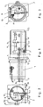
- Fig. 1 shows a cylindrical holder (H) Thermal head (10), the thermal dot line (TZ) by a Slot of the holder (H) protrudes on the casing side.
- the Holding cylinder (H) is in a flange (12) through a Clamping screw (11) held like a clamp; the flange (12) serves for attachment in a not shown Card conveyor device, which the card to be labeled (K), which carries the thermochromic layer (TS), perpendicular to the picture Line by line past the topic line (TZ).
- K the card to be labeled
- TS thermochromic layer
- the thermal labeling head (10) consists of thermally conductive Ceramic and is made with a solid head support (9) Aluminum or other heat-conducting metal with the Holder (H) connected, which leads the heat to the outside is introduced when heating the heating elements.
- Fig. 2 shows a side view of the front of the Holder (H) with the surrounding flange (12) and the Clamp clamp (11).
- the Head (10) On the massive head support (9) is the Head (10) attached, with its thermopoint line (TZ) looks out of the holding cylinder. Before the pressure line (TZ) the card to be labeled (K) is shown, which in the Transport direction (TR) is gradually promoted.
- thermal transfer printer lies between the card (K) and the pressure dot line (TZ) an ink ribbon (FB) with a Transfer ink.
- An optical-electrical ribbon sensor (2) signals the presence or absence of the ribbon (FB), whereby the control device each choose the appropriate control program.
- Fig. 3 shows a view of the flange (12).
- Holder (H) is the head support (9) with the Thermal labeling head (10) can be seen.
- a thermal sensor (7) attached, which is preferably a PTC resistor, so one with a positive temperature coefficient.
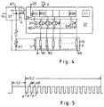
- Fig. 4 shows a block diagram of a control device of the thermally controlled labeling line of the Labeling head (10).
- the individual pressure points exist of electrical resistors (R1 - RN), each in known manner from an associated transistor (T1 - TN) be energized, depending on how the state in each case associated register element of a control register (RS1 - RSN).
- the control register (RS1 - RSN) is, for example Shift register into which the print information (DI) of the each line to be printed by the control device (ST) is to be inserted.
- the information in the Shift register line is each in an associated Gate (G1 - GN) linked to a heating control signal (HZ), its output on the control transistor (T1 - TN) is assigned accordingly.
- the control device (ST) contains a clock (CL), through which the control program sequence is controlled.
- CL clock
- DÜ data transmission line
- the operating voltage (U) comes from the power supply (NT) Control device (ST) and the supply voltage (UV), the the transistors (T1 - TN) and via this the Heating resistors (R1 - RN) is supplied and depends on the temperature signal from the temperature sensor (7) is controlled, which is attached to the head holder (9). It is preferably a PTC resistor that is connected to suitable linearization resistors (P1, P2) adjustable is connected in its characteristics and with the Control electrode of a regulator transistor (RT) connected in this way is that the supply voltage (UV) is the lower the higher the temperature at the sensor and thus its Resistance is.
- P1, P2 suitable linearization resistors
- RT regulator transistor
- the control program is dependent on the signal of the Ribbon sensor (2) on the labeling of the thermochromic layer set.
- Fig. 5 shows an energization signal of a heating resistor in temporal course.
- LZ initial deletion time
- SZ writing time
- P short Break times
- HP heating phases
- the pulse-pause ratio is chosen so that the temperature the heating elements to a temperature of approx. 170 ° C, so above the color change temperature, then increases in one Range fluctuates above the color change temperature.
- the power is switched off completely, causing a rapid cooling below the extinguishing temperature occurs.
- the next line is below the writing line promoted and the whole process starts again, whereby again when deleting all and to write corresponding pressure points are specified.
- Thermochromic layer (TS) has an elevated temperature, this has an increased lubricity, and thus the layer and the head are transported further Spared the layer; there is a kind Lubrication effect.
Landscapes
- Electronic Switches (AREA)
Abstract
Description
- Fig. 1
- zeigt einen teilweise geöffneten Halter mit einem Punktzeilen-Schreibkopf,
- Fig. 2
- zeigt eine Stirnansicht zu Fig. 1,
- Fig. 3
- zeigt eine Ansicht zu Fig. 1 bei abgenommenem Steckeranschluß,
- Fig. 4
- zeigt ein Schaltschema zur Ansteuerung einer Druckpunktzeile,
- Fig. 5
- zeigt ein Bestromungszeitdiagramm eines Druckzeilenpunktes.
Claims (14)
- Verfahren zum Löschen und Bedrucken eines Trägers (K) einer Thermochromic-Schicht (TS), dadurch gekennzeichnet, daß diese durch Aufheizen auf eine Löschtemperatur während einer Löschzeit in einen farblosen Grundzustand verbracht wird und durch lokales Verbringen über eine Farbumschlagtemperatur für eine Farbumschlagzeit und anschließendes schnelles Abkühlen unter die Löschtemperatur mit einem entsprechenden Druckmuster versehen wird, indem eine elektrisch beheizbare Thermopunktzeile (TZ) dem vorgesehenen Druckmuster gemäß punktuell entsprechend erhitzt und abgekühlt wird und jeweils anschließend in eine nächste Punktzeile verbracht wird, bis sämtliche zu schreibenden Punktzeilen unter die Thermopunktzeile (TZ) verbracht worden sind.
- Verfahren nach Anspruch 1, dadurch gekennzeichnet, daß wahrend der Schreibphase (SZ) eine Bestromung der Thermopunkte (R1 - RN) mit einer Puls-Längenmodulation so erfolgt, daß deren Temperatur in einem Bereich über der Farbumschlagtemperatur pendelt.
- Verfahren nach Anspruch 2, dadurch gekennzeichnet, daß bei der Pulslängenmodulation das Puls-Pausenverhältnis etwa 2 zu 1 beträgt.
- Verfahren nach Anspruch 3, dadurch gekennzeichnet, daß das Puls-Pausenverhältnis etwa 9 µs zu 5 µs beträgt.
- Verfahren nach einem der Ansprüche 2 bis 4, dadurch gekennzeichnet, daß das Puls-Pausenverhältnis jeweils zwischen einem minimalen und einem maximalen Verhältnis, abhängig von der Anzahl der jeweils zu bestromenden Thermopunkte (R1 - RN) zu deren Gesamtzahl (N) eingestellt wird, so daß die Farbumschlagtemperatur in der Schreibphase (SZ) leicht überschritten wird.
- Verfahren nach einem der vorstehenden Ansprüche, dadurch gekennzeichnet, daß die Heizelemente der Thermopunkte (R1 - RN) jeweils mit einer Betriebsspannung (UV), die abhängig von einer jeweiligen mittleren Temperatur eines Trägers (9) der Thermopunktzeile (TZ) eingestellt ist, gesteuert betrieben werden.
- Verfahren nach einem der vorstehenden Ansprüche, dadurch gekennzeichnet, daß die Länge der Löschphase (LZ) jeweils ausgehend von einer maximal vorgegebenen Löschzeit abängig von der jeweiligen Anzahl aufeinanderfolgend beschriebenen Zeilen schrittweise bis auf eine minimal vorgegebene Löschzeit herabgesetzt wird, so daß die Löschtemperatur in der Löschphase (LZ) gerade erreicht wird.
- Verfahren nach einem der vorstehenden Ansprüche, dadurch gekennzeichnet, daß die Thermochromic-Schicht (TS) an der Thermopunktzeile (TZ) in der Löschphase (LZ) auf ca. 120°C aufgeheizt wird und die zu beschreibenden Punkte jeweils in der Schreibphase (SZ) bis auf ca. 170°C weiter aufgeheizt werden.
- Vorrichtung zur Durchführung des Verfahrens nach einem der Ansprüche 1 bis 8, dadurch gekennzeichnet, daß die Thermopunktzeile (TZ) auf einem keramischen Thermokopf (10) angeordnet ist, der an einem Gehäuse (H) mit einem massiven, gut wärmeleitenden metallischen Kopfträger (9) wärmeableitend montiert ist, an dem ein Temperatursensor (7) befestigt ist, dessen Sensorsignal einem Netzteil (NT) steuernd zugeführt ist, das davon abhängig eine Betriebsspannung (UV) der Heizwiderstände der Thermopunkte (R1 - RN) der Thermopunktzeile (TZ) liefert.
- Vorrichtung nach Anspruch 9, dadurch gekennzeichnet, daß der Temperatursensor (7) ein PTC-Widerstand ist.
- Vorrichtung nach Anspruch 10, dadurch gekennzeichnet, daß der Temperatursensor (7) parallel und/oder seriell mit einstellbaren Widerständen oder Potentiometern (P1, P2) beschaltet ist.
- Vorrichtung nach einem der Ansprüche 9 bis 11, dadurch gekennzeichnet, daß neben der Thermopunktzeile (TZ) ein Farbbandsensor (2) angeordnet ist, dessen Sensorsignal einer Steuervorrichtung (ST) zugeführt ist, die jeweils ein Steuerprogramm gemäß dem Verfahren durchführt, wenn kein Farbband (FB) vom Farbbandsensor (2) erkannt wird.
- Vorrichtung nach einem der Ansprüche 9 bis 12, dadurch gekennzeichnet, daß die Heizwiderstände der Thermopunkte (R1 - RN) je von Transistoren (T1 - TN) angesteuert sind, die in der Löschphase (LZ) alle voll eingeschaltet gesteuert sind und in der Schreibphase (SZ) über ein puls-pausensteuerndes Signal (HZ) jeweils nur die, die über ein jeweils zugehöriges Schreibregisterelement (RS1 - RSN) ausgewählt sind, zeitweilig eingeschaltet sind.
- Vorrichtung nach Anspruch 13, dadurch gekennzeichnet, daß die Schreibregisterelemente (RS1 - RSN) als ein Schieberegister zusammengeschaltet sind und jeweils pro Zeilenausgabe über eine Datenübertragungsverbindung (DÜ) mit einer Druckinformation (DI) von einer externen Steuervorrichtung beschickt werden.
Applications Claiming Priority (2)
| Application Number | Priority Date | Filing Date | Title |
|---|---|---|---|
| DE19811539 | 1998-03-17 | ||
| DE19811539A DE19811539A1 (de) | 1998-03-17 | 1998-03-17 | Verfahren und Vorrichtung zum Bedrucken von Thermochromic-Schichten |
Publications (3)
| Publication Number | Publication Date |
|---|---|
| EP0943443A2 true EP0943443A2 (de) | 1999-09-22 |
| EP0943443A3 EP0943443A3 (de) | 2000-04-05 |
| EP0943443B1 EP0943443B1 (de) | 2005-03-02 |
Family
ID=7861188
Family Applications (1)
| Application Number | Title | Priority Date | Filing Date |
|---|---|---|---|
| EP99104836A Expired - Lifetime EP0943443B1 (de) | 1998-03-17 | 1999-03-11 | Verfahren und Vorrichtung zum Bedrucken von Thermochromic-Schichten |
Country Status (2)
| Country | Link |
|---|---|
| EP (1) | EP0943443B1 (de) |
| DE (2) | DE19811539A1 (de) |
Family Cites Families (8)
| Publication number | Priority date | Publication date | Assignee | Title |
|---|---|---|---|---|
| JPS61286170A (ja) * | 1985-06-14 | 1986-12-16 | Oki Electric Ind Co Ltd | サ−マルヘツド駆動回路 |
| EP0273738B1 (de) * | 1986-12-27 | 1993-03-17 | Canon Kabushiki Kaisha | Drucker mit Korrekturfunktion |
| JP3017828B2 (ja) * | 1991-03-29 | 2000-03-13 | 株式会社東芝 | 記録装置 |
| US5552364A (en) * | 1992-03-09 | 1996-09-03 | Ricoh Company, Ltd. | Reversible theromosensitive coloring recording method, recording medium and recording apparatus for the recording method |
| US5371522A (en) * | 1992-03-18 | 1994-12-06 | Ricoh Company, Ltd. | Apparatus for erasing and recording data in a thermosensitive recording medium |
| JPH0890934A (ja) * | 1994-09-22 | 1996-04-09 | Almex Inc | 熱可逆特性を有するリライトカードの印字方法と印字装置 |
| JPH09174892A (ja) * | 1995-12-28 | 1997-07-08 | Oki Electric Ind Co Ltd | 記録媒体処理装置 |
| JP3674824B2 (ja) * | 1997-12-27 | 2005-07-27 | 株式会社リコー | 印字・消去方法 |
-
1998
- 1998-03-17 DE DE19811539A patent/DE19811539A1/de not_active Withdrawn
-
1999
- 1999-03-11 DE DE59911671T patent/DE59911671D1/de not_active Expired - Lifetime
- 1999-03-11 EP EP99104836A patent/EP0943443B1/de not_active Expired - Lifetime
Also Published As
| Publication number | Publication date |
|---|---|
| DE19811539A1 (de) | 1999-09-23 |
| EP0943443A3 (de) | 2000-04-05 |
| DE59911671D1 (de) | 2005-04-07 |
| EP0943443B1 (de) | 2005-03-02 |
Similar Documents
| Publication | Publication Date | Title |
|---|---|---|
| EP0431155B1 (de) | Vorrichtung zum aufbringen von informationen auf einen optischen aufzeichnungsträger | |
| DE4445243C2 (de) | Temperaturfühler | |
| DE3928732C2 (de) | Tintenstrahlaufzeichnungsgerät | |
| DE2659398A1 (de) | Heizvorrichtung fuer schreibkoepfe in tintenmosaikschreibeinrichtungen | |
| DE69527007T2 (de) | Tintenstrahldruckverfahren und -gerät | |
| DE2315226B2 (de) | Aufzeichnungsvorrichtung | |
| DE3751191T2 (de) | Wärmeübertragungsdrucker. | |
| DE4003118C2 (de) | Balkencode-Drucker | |
| DE4220003A1 (de) | Thermodrucker | |
| DE3325857A1 (de) | Waermedrucker mit farbuebertragung | |
| DE203056T1 (de) | Thermaluebertragungsfarbwiedergabegeraet und band. | |
| DE60115184T2 (de) | Tintenstrahldrucksystem, Tintenbehälter und Herstellungsverfahren | |
| DE69937092T2 (de) | Verfahren und Vorrichtung zum Löschen von gedruckten Daten einer wiederbeschreibbarer Karte | |
| DE69303697T2 (de) | Druckverfahren durch Wärmeübertragung | |
| DE60303640T2 (de) | Gerät zum thermischen Aktivieren und Drucker für wärmeempfindliche Klebefolie | |
| DE69319083T2 (de) | Energieversorgung zur Einzelsteuerung der Energie für integrierte Treiber-Heizwiderstände in einem Tintenstrahl-Wärmedruckkopf | |
| DE3750170T2 (de) | Drucksteuerung für einen Wärmedruckkopf. | |
| DE69605503T2 (de) | Erwärmung eines Tintenstrahldruckkopfes | |
| DE69211241T2 (de) | Vorrichtung zur Wärmebehandlung und Reparatur von Turbinenschaufeln | |
| EP0943443A2 (de) | Verfahren und Vorrichtung zum Bedrucken von Thermochromic-Schichten | |
| DE4337542A1 (de) | Anordnung für eine ETR-Druckkopfansteuerung | |
| DE3721925C2 (de) | ||
| DE29504576U1 (de) | Druckkopfthermosteuerung | |
| EP0536526A2 (de) | Verfahren zum Steuern der Speisung eines Thermodruckheizelements | |
| DE3227589A1 (de) | Druckkopf fuer einen mehrfarben-punktdrucker |
Legal Events
| Date | Code | Title | Description |
|---|---|---|---|
| PUAI | Public reference made under article 153(3) epc to a published international application that has entered the european phase |
Free format text: ORIGINAL CODE: 0009012 |
|
| AK | Designated contracting states |
Kind code of ref document: A2 Designated state(s): DE FR GB NL |
|
| AX | Request for extension of the european patent |
Free format text: AL;LT;LV;MK;RO;SI |
|
| PUAL | Search report despatched |
Free format text: ORIGINAL CODE: 0009013 |
|
| AK | Designated contracting states |
Kind code of ref document: A3 Designated state(s): AT BE CH CY DE DK ES FI FR GB GR IE IT LI LU MC NL PT SE |
|
| AX | Request for extension of the european patent |
Free format text: AL;LT;LV;MK;RO;SI |
|
| RIC1 | Information provided on ipc code assigned before grant |
Free format text: 7B 41J 2/365 A, 7B 41J 2/355 B, 7B 41J 2/315 B |
|
| 17P | Request for examination filed |
Effective date: 20000921 |
|
| AKX | Designation fees paid |
Free format text: DE FR GB NL |
|
| 17Q | First examination report despatched |
Effective date: 20040421 |
|
| GRAP | Despatch of communication of intention to grant a patent |
Free format text: ORIGINAL CODE: EPIDOSNIGR1 |
|
| GRAP | Despatch of communication of intention to grant a patent |
Free format text: ORIGINAL CODE: EPIDOSNIGR1 |
|
| RAP1 | Party data changed (applicant data changed or rights of an application transferred) |
Owner name: BOEWE CARDTEC GMBH |
|
| GRAS | Grant fee paid |
Free format text: ORIGINAL CODE: EPIDOSNIGR3 |
|
| GRAA | (expected) grant |
Free format text: ORIGINAL CODE: 0009210 |
|
| AK | Designated contracting states |
Kind code of ref document: B1 Designated state(s): DE FR GB NL |
|
| PG25 | Lapsed in a contracting state [announced via postgrant information from national office to epo] |
Ref country code: NL Free format text: LAPSE BECAUSE OF FAILURE TO SUBMIT A TRANSLATION OF THE DESCRIPTION OR TO PAY THE FEE WITHIN THE PRESCRIBED TIME-LIMIT Effective date: 20050302 Ref country code: GB Free format text: LAPSE BECAUSE OF FAILURE TO SUBMIT A TRANSLATION OF THE DESCRIPTION OR TO PAY THE FEE WITHIN THE PRESCRIBED TIME-LIMIT Effective date: 20050302 |
|
| REG | Reference to a national code |
Ref country code: GB Ref legal event code: FG4D Free format text: NOT ENGLISH |
|
| REF | Corresponds to: |
Ref document number: 59911671 Country of ref document: DE Date of ref document: 20050407 Kind code of ref document: P |
|
| NLV1 | Nl: lapsed or annulled due to failure to fulfill the requirements of art. 29p and 29m of the patents act | ||
| GBV | Gb: ep patent (uk) treated as always having been void in accordance with gb section 77(7)/1977 [no translation filed] |
Effective date: 20050302 |
|
| PLBE | No opposition filed within time limit |
Free format text: ORIGINAL CODE: 0009261 |
|
| STAA | Information on the status of an ep patent application or granted ep patent |
Free format text: STATUS: NO OPPOSITION FILED WITHIN TIME LIMIT |
|
| ET | Fr: translation filed | ||
| 26N | No opposition filed |
Effective date: 20051205 |
|
| REG | Reference to a national code |
Ref country code: FR Ref legal event code: CL |
|
| REG | Reference to a national code |
Ref country code: DE Ref legal event code: R081 Ref document number: 59911671 Country of ref document: DE Owner name: ATLANTIC ZEISER GMBH, DE Free format text: FORMER OWNER: BOEWE CARDTEC GMBH, 33106 PADERBORN, DE Effective date: 20110412 |
|
| REG | Reference to a national code |
Ref country code: FR Ref legal event code: TP |
|
| PGFP | Annual fee paid to national office [announced via postgrant information from national office to epo] |
Ref country code: FR Payment date: 20120403 Year of fee payment: 14 |
|
| PGFP | Annual fee paid to national office [announced via postgrant information from national office to epo] |
Ref country code: DE Payment date: 20120530 Year of fee payment: 14 |
|
| REG | Reference to a national code |
Ref country code: FR Ref legal event code: ST Effective date: 20131129 |
|
| REG | Reference to a national code |
Ref country code: DE Ref legal event code: R119 Ref document number: 59911671 Country of ref document: DE Effective date: 20131001 |
|
| PG25 | Lapsed in a contracting state [announced via postgrant information from national office to epo] |
Ref country code: DE Free format text: LAPSE BECAUSE OF NON-PAYMENT OF DUE FEES Effective date: 20131001 Ref country code: FR Free format text: LAPSE BECAUSE OF NON-PAYMENT OF DUE FEES Effective date: 20130402 |