EP0943456A1 - Flexibler Behälter für ein Schreibgerät - Google Patents
Flexibler Behälter für ein Schreibgerät Download PDFInfo
- Publication number
- EP0943456A1 EP0943456A1 EP98105069A EP98105069A EP0943456A1 EP 0943456 A1 EP0943456 A1 EP 0943456A1 EP 98105069 A EP98105069 A EP 98105069A EP 98105069 A EP98105069 A EP 98105069A EP 0943456 A1 EP0943456 A1 EP 0943456A1
- Authority
- EP
- European Patent Office
- Prior art keywords
- tank
- fact
- writing instrument
- ink
- deform
- Prior art date
- Legal status (The legal status is an assumption and is not a legal conclusion. Google has not performed a legal analysis and makes no representation as to the accuracy of the status listed.)
- Withdrawn
Links
- 239000000463 material Substances 0.000 claims abstract description 3
- 238000001125 extrusion Methods 0.000 claims 1
- 239000000976 ink Substances 0.000 description 33
- 238000004519 manufacturing process Methods 0.000 description 9
- 239000003570 air Substances 0.000 description 6
- 239000000126 substance Substances 0.000 description 4
- 238000003466 welding Methods 0.000 description 4
- 239000007788 liquid Substances 0.000 description 3
- -1 polypropylene Polymers 0.000 description 3
- 239000004698 Polyethylene Substances 0.000 description 2
- 230000032683 aging Effects 0.000 description 2
- 230000006866 deterioration Effects 0.000 description 2
- 239000000835 fiber Substances 0.000 description 2
- 229920001684 low density polyethylene Polymers 0.000 description 2
- 239000004702 low-density polyethylene Substances 0.000 description 2
- 239000000203 mixture Substances 0.000 description 2
- 239000004033 plastic Substances 0.000 description 2
- 229920003023 plastic Polymers 0.000 description 2
- 229920000728 polyester Polymers 0.000 description 2
- 229920000573 polyethylene Polymers 0.000 description 2
- XLYOFNOQVPJJNP-UHFFFAOYSA-N water Substances O XLYOFNOQVPJJNP-UHFFFAOYSA-N 0.000 description 2
- VGGSQFUCUMXWEO-UHFFFAOYSA-N Ethene Chemical compound C=C VGGSQFUCUMXWEO-UHFFFAOYSA-N 0.000 description 1
- 239000004743 Polypropylene Substances 0.000 description 1
- 229910052782 aluminium Inorganic materials 0.000 description 1
- XAGFODPZIPBFFR-UHFFFAOYSA-N aluminium Chemical compound [Al] XAGFODPZIPBFFR-UHFFFAOYSA-N 0.000 description 1
- 239000012080 ambient air Substances 0.000 description 1
- 238000005119 centrifugation Methods 0.000 description 1
- 230000008878 coupling Effects 0.000 description 1
- 238000010168 coupling process Methods 0.000 description 1
- 238000005859 coupling reaction Methods 0.000 description 1
- 238000002788 crimping Methods 0.000 description 1
- 230000007423 decrease Effects 0.000 description 1
- 230000001419 dependent effect Effects 0.000 description 1
- 230000018109 developmental process Effects 0.000 description 1
- 230000000694 effects Effects 0.000 description 1
- 239000003292 glue Substances 0.000 description 1
- 238000003780 insertion Methods 0.000 description 1
- 230000037431 insertion Effects 0.000 description 1
- 229910052751 metal Inorganic materials 0.000 description 1
- 239000002184 metal Substances 0.000 description 1
- 238000000034 method Methods 0.000 description 1
- 235000011837 pasties Nutrition 0.000 description 1
- 229920001155 polypropylene Polymers 0.000 description 1
- 238000010992 reflux Methods 0.000 description 1
- 238000007789 sealing Methods 0.000 description 1
- 125000006850 spacer group Chemical group 0.000 description 1
- KKEYFWRCBNTPAC-UHFFFAOYSA-L terephthalate(2-) Chemical compound [O-]C(=O)C1=CC=C(C([O-])=O)C=C1 KKEYFWRCBNTPAC-UHFFFAOYSA-L 0.000 description 1
- 238000002604 ultrasonography Methods 0.000 description 1
Images


Classifications
-
- B—PERFORMING OPERATIONS; TRANSPORTING
- B43—WRITING OR DRAWING IMPLEMENTS; BUREAU ACCESSORIES
- B43K—IMPLEMENTS FOR WRITING OR DRAWING
- B43K5/00—Pens with ink reservoirs in holders, e.g. fountain-pens
- B43K5/02—Ink reservoirs
- B43K5/04—Ink reservoirs flexible
-
- B—PERFORMING OPERATIONS; TRANSPORTING
- B43—WRITING OR DRAWING IMPLEMENTS; BUREAU ACCESSORIES
- B43K—IMPLEMENTS FOR WRITING OR DRAWING
- B43K7/00—Ball-point pens
- B43K7/02—Ink reservoirs; Ink cartridges
Definitions
- the present invention relates to an ink tank intended for use in a writing instrument.
- ink tanks for writing instruments especially cartridges ink used in fountain pens. These cartridges usually consist of a cylindrical tank plastic injected and a ball fixed between two spacers that prevent ink from flowing. During use, we put this cartridge in the pen pen, the ball sealing the cartridge is pushed to inside the cartridge thus allowing the ink to flow towards the pen.
- the so-called 'pasty' inks i.e. those normally having a viscosity greater than 8000 cps, are usually contained in a tube in polypropylene fitted with a metal billed tip. If the tube diameter is too large (greater than 2.6 millimeters), or if the viscosity is lower, it is necessary to introduce a layer of substance at high surface tension to prevent ink leakage through the free end of the tube. Once injected, the ink is brought into contact with the ball by centrifugation, the resulting absence of air means that the ink does not leak from the back. If the viscosity decreases, the surface tension is normally no longer sufficient to prevent leakage from the back of the tube.
- the tip is provided with a internal spring which pushes the ball towards the internal part crimping to seal the system.
- the ball is pressed against the action of the spring, towards its seat and frees up a passage surface around which the ink can escape.
- Some glue dispensers and pens correctors use this principle. These devices are complex and expensive to manufacture.
- the object of the present invention is to remedy the disadvantages mentioned above by offering a reservoir for writing instrument that balances pressure without having to replace the ink used with air. Thanks to this device, aging and deterioration of the qualities of the ink due to its contact with ambient air. It is also possible to use all kinds of inks without them have specific viscosity characteristics or that it is necessary to add a layer of high surface tension substance, so completely independent of the type of writing system adopted (billed point, roller, felt, fineliner or other).
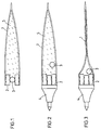
- Figure 1 is a cross-sectional view of a ink tank for writing instrument according to the invention, the latter being closed.
- Figure 2 is a view identical to Figure 1, the tank being mounted on the tip of an instrument to write.
- Figure 3 illustrates the reservoir of Figures 1 and 2 when empty.
- Figure 4 is a side view of a tank according the invention mounted on a ball point.
- Figure 5 is a partial sectional view of the ball point illustrated in figure 4.
- Figure 6 shows a writing instrument comprising a tank object of the invention and a first form of execution of means to act on said tank, the tank being full.
- Figure 7 is a view similar to that shown in Figure 6, the tank being half empty.
- Figure 8 illustrates a writing instrument comprising a tank object of the invention and a second embodiment of the means interacting with The reservoir.
- Figure 9 illustrates a writing instrument comprising a tank object of the invention and a third embodiment of the means interacting with The reservoir.
- Figure 10 illustrates a writing instrument comprising a tank object of the invention and a fourth embodiment of the means interacting with The reservoir.
- Figure 11 is a side view of a tank flexible according to the invention mounted on a ball point, the reservoir comprising at the distal end of the tip means for filling.
- Figure 12 is a view identical to that illustrated in Figure 11, during the filling operation.
- Figure 13 is an exploded view in partial section a writing instrument comprising a reservoir according to the invention and provided with an interchangeable tip.
- the flexible tank is consisting of a deformable bag 1 closed with a ring 2 comprising a ball 3 held in a housing.
- the sachet 1 can consist of a sheet composed of several layers of different material.
- the sheet constituting the sachet can include a first layer of PET (terephthalate polyethylene) 12 microns thick, one second aluminum layer about 8 microns thick and a third layer of low density polyethylene (LDPE low density polyetylen) with a thickness of about 60 microns.
- PET terephthalate polyethylene
- LDPE low density polyetylen low density polyethylene
- Another method of making sachet 1 consists in obtaining a tube by extruding a composition based on polyester combined with polyethylene. This mode of manufacturing requires only a transverse weld to close the bag. Preferably use a hot contact for this type of manufacturing.
- Bags made using one of two methods described above and with the compositions mentioned have the advantage of being both impermeable to ink and lightfast components.
- the sachet thus obtained is then welded to the ring in plastic 2.
- Figure 2 illustrates the tank coupled with a ball point.
- Tip 4 when coupling, penetrates the ball 3 inside the bag 1 and thus allows ink 5 to supply the tip 4.
- Figure 3 illustrates the instrument to be written when the bag 1 is practically empty.
- Figures 4 and 5 illustrate a variant in which the bag 1 forming a flexible tank is mounted directly (by welding for example) on tip 6 of a writing instrument. The ink flowing towards the tip at ball through a passage 7. This assembly can then be arranged in the rigid body 8 of an instrument to write as shown in figure 6.
- the deformation of the bag allows to equalize the pressure without however, replace ink 5 with the air.
- the fact of not having a supply of fresh air reduces the aging speed of the ink 5. Thanks to this tank, it is also not necessary to provide a high viscosity mass to hold the ink in the reservoir tube thus formed.
- Figures 7 to 10 illustrate a writing instrument having means for mechanical deformation the flexible tank 1.
- the flexible tank consisting of bag 1 can be pressurized and allow use under the conditions set out above. This has an advantage over traditional rigid tanks, which must be put under pressure during manufacturing, which requires complex and expensive manufacturing processes.
- Figure 7 represents a writing instrument in whose body is arranged a flexible tank 1 according to the invention.
- FIG. 8 shows the instrument when part of the ink 5 has been used.
- FIG. 8 illustrates a variant in which the rear end of the instrument body is threaded and can accommodate a plug acting as a piston fitted with a thread. By screwing the latter more or less depending on the use, we put the ink 5 sous pressure by compressing the bag 1.
- Figure 10 illustrates another variant in which the member making it possible to compress the reservoir 1 consists of a cap 12 cylindrical elastic with annular grooves on its periphery.
- Figure 11 illustrates a variant of a tank flexible according to the invention mounted on a ball point 6.
- the bag 1 is welded at its end opposite the tip on the outer surface of a cylindrical ring 13.
- the ring 13 partially emerges from bag 1 and can accueuillir a removable closure member, shown in drawing in the form of a plug 14.
- the flexible tank 1 provided with its plug 14 is mounted on an intermediate element 16.
- This element 16 is shaped so that it can be introduced into the body of a writing instrument 18, the central part of element 16 bearing in position assembled against the annular surface of the body 18.
- the tip 17 of the instrument has a recess whose dimensions correspond to those of the lateral part of item 16.
- This embodiment allows the replacement of the tip 17 in case of wear for example.
Landscapes
- Engineering & Computer Science (AREA)
- Mechanical Engineering (AREA)
- Pens And Brushes (AREA)
Priority Applications (1)
| Application Number | Priority Date | Filing Date | Title |
|---|---|---|---|
| EP98105069A EP0943456A1 (de) | 1998-03-20 | 1998-03-20 | Flexibler Behälter für ein Schreibgerät |
Applications Claiming Priority (1)
| Application Number | Priority Date | Filing Date | Title |
|---|---|---|---|
| EP98105069A EP0943456A1 (de) | 1998-03-20 | 1998-03-20 | Flexibler Behälter für ein Schreibgerät |
Publications (1)
| Publication Number | Publication Date |
|---|---|
| EP0943456A1 true EP0943456A1 (de) | 1999-09-22 |
Family
ID=8231625
Family Applications (1)
| Application Number | Title | Priority Date | Filing Date |
|---|---|---|---|
| EP98105069A Withdrawn EP0943456A1 (de) | 1998-03-20 | 1998-03-20 | Flexibler Behälter für ein Schreibgerät |
Country Status (1)
| Country | Link |
|---|---|
| EP (1) | EP0943456A1 (de) |
Citations (10)
| Publication number | Priority date | Publication date | Assignee | Title |
|---|---|---|---|---|
| US1495871A (en) * | 1923-03-30 | 1924-05-27 | Fred H Ohland | Fountain pen |
| GB602101A (en) * | 1945-05-01 | 1948-05-20 | Laszlo Jozsef Biro | Improvements in reservon writing instruments |
| CH255994A (fr) * | 1945-04-19 | 1948-07-31 | George Martin Henry | Stylographe à bille. |
| US2499771A (en) * | 1948-08-10 | 1950-03-07 | Arthur F O'connor | Writing instrument |
| FR1048243A (fr) * | 1952-01-11 | 1953-12-21 | Etablisseements Christian Soc | Dispositif d'adaptation des poches réservoirs aux sectiens des stylographes et analogues |
| FR1064496A (fr) * | 1952-10-17 | 1954-05-13 | Perfectionnements aux dispositifs de remplissage des porte-plume à réservoir | |
| FR86673E (fr) * | 1964-10-27 | 1966-03-25 | Christian Ets | Dispositif d'adaptation des poches-réservoirs aux sections des stylographes et analogues |
| DE1952108A1 (de) * | 1969-10-16 | 1971-04-29 | Bernhard Rehn | Kugelschreiber mit lageunabhaengiger Funktion |
| WO1981001129A1 (en) * | 1979-10-26 | 1981-04-30 | J Reuchlin | Fluid recipient |
| DE3937296A1 (de) * | 1989-11-09 | 1991-05-16 | Henkel Kgaa | Vorrichtung zum auftragen eines niedrigviskosen stoffes |
-
1998
- 1998-03-20 EP EP98105069A patent/EP0943456A1/de not_active Withdrawn
Patent Citations (10)
| Publication number | Priority date | Publication date | Assignee | Title |
|---|---|---|---|---|
| US1495871A (en) * | 1923-03-30 | 1924-05-27 | Fred H Ohland | Fountain pen |
| CH255994A (fr) * | 1945-04-19 | 1948-07-31 | George Martin Henry | Stylographe à bille. |
| GB602101A (en) * | 1945-05-01 | 1948-05-20 | Laszlo Jozsef Biro | Improvements in reservon writing instruments |
| US2499771A (en) * | 1948-08-10 | 1950-03-07 | Arthur F O'connor | Writing instrument |
| FR1048243A (fr) * | 1952-01-11 | 1953-12-21 | Etablisseements Christian Soc | Dispositif d'adaptation des poches réservoirs aux sectiens des stylographes et analogues |
| FR1064496A (fr) * | 1952-10-17 | 1954-05-13 | Perfectionnements aux dispositifs de remplissage des porte-plume à réservoir | |
| FR86673E (fr) * | 1964-10-27 | 1966-03-25 | Christian Ets | Dispositif d'adaptation des poches-réservoirs aux sections des stylographes et analogues |
| DE1952108A1 (de) * | 1969-10-16 | 1971-04-29 | Bernhard Rehn | Kugelschreiber mit lageunabhaengiger Funktion |
| WO1981001129A1 (en) * | 1979-10-26 | 1981-04-30 | J Reuchlin | Fluid recipient |
| DE3937296A1 (de) * | 1989-11-09 | 1991-05-16 | Henkel Kgaa | Vorrichtung zum auftragen eines niedrigviskosen stoffes |
Similar Documents
| Publication | Publication Date | Title |
|---|---|---|
| EP2475463B1 (de) | Vorrichtung zur ausgabe einer flüssigkeit | |
| CA2358151C (fr) | Applicateur et recipient muni d'un tel applicateur | |
| EP2828097B1 (de) | Flüssigkeitsapplikationsvorrichtung und verwendungen davon | |
| FR2492321A1 (fr) | Stylo comportant un clapet manoeuvrable de l'exterieur dans l'arrivee d'encre notamment pour tracer des lettres fines | |
| CA2308865A1 (fr) | Tete de distribution et recipient ainsi equipe | |
| CA2666557A1 (fr) | Instrument d'ecriture sans capuchon | |
| FR2829115A1 (fr) | Ensemble pour le conditionnement et l'application d'un produit, notamment cosmetique | |
| FR2528361A1 (fr) | Instrument d'ecriture et son procede de fabrication | |
| EP0803381A1 (de) | Pufferbehälter für Flüssigkeitsschreibgerät und Schreibgerät mit einem solchen Behälter | |
| EP1036013A1 (de) | Vorrichtung zum aufbewahren von flüssigkeit mit tropfenspender | |
| EP0681924A1 (de) | Flüssigkeitsschreibgerät, insbesondere auf Lösemittelbasis | |
| EP0821775B1 (de) | Konstruktion eines einlassventils | |
| EP2362835B1 (de) | Schreibgerät und kappe mit innennuten für ein schreibgerät | |
| FR2771285A1 (fr) | Paillette avec bouchon bipartite | |
| FR2615761A1 (fr) | Dispositif applicateur de liquide | |
| EP1718477A1 (de) | Mit einer ventilzuführvorrichtung versehenes schreibgerät | |
| FR2612845A1 (fr) | Instrument d'ecriture ou applicateur de liquide | |
| FR2633519A1 (fr) | Seringue comprenant un corps a chambre de volume variable et un dispositif d'aiguille assemblable audit corps | |
| FR2771284A1 (fr) | Paillette avec insert adaptateur | |
| FR2504861A1 (fr) | Stylo a bille perfectionne | |
| FR2772665A3 (fr) | Instrument d'ecriture | |
| FR2682894A1 (fr) | Applicateur de liquide. | |
| FR2896183A1 (fr) | Instrument d'ecriture comprenant un dispositif de mise a l'air libre du reservoir | |
| CH264938A (fr) | Stylographe à bille. | |
| EP0518301A2 (de) | Sprühkopf |
Legal Events
| Date | Code | Title | Description |
|---|---|---|---|
| PUAI | Public reference made under article 153(3) epc to a published international application that has entered the european phase |
Free format text: ORIGINAL CODE: 0009012 |
|
| AK | Designated contracting states |
Kind code of ref document: A1 Designated state(s): AT BE CH DE DK ES FI FR GB GR IE IT LI LU MC NL PT SE |
|
| AX | Request for extension of the european patent |
Free format text: AL;LT;LV;MK;RO;SI |
|
| AKX | Designation fees paid | ||
| REG | Reference to a national code |
Ref country code: DE Ref legal event code: 8566 |
|
| STAA | Information on the status of an ep patent application or granted ep patent |
Free format text: STATUS: THE APPLICATION IS DEEMED TO BE WITHDRAWN |
|
| 18D | Application deemed to be withdrawn |
Effective date: 20000323 |