EP0943499B1 - Airbag avec bande de retenue - Google Patents
Airbag avec bande de retenue Download PDFInfo
- Publication number
- EP0943499B1 EP0943499B1 EP99102515A EP99102515A EP0943499B1 EP 0943499 B1 EP0943499 B1 EP 0943499B1 EP 99102515 A EP99102515 A EP 99102515A EP 99102515 A EP99102515 A EP 99102515A EP 0943499 B1 EP0943499 B1 EP 0943499B1
- Authority
- EP
- European Patent Office
- Prior art keywords
- airbag
- tether
- occupant
- coil
- vehicle
- Prior art date
- Legal status (The legal status is an assumption and is not a legal conclusion. Google has not performed a legal analysis and makes no representation as to the accuracy of the status listed.)
- Expired - Lifetime
Links
Images

Classifications
-
- B—PERFORMING OPERATIONS; TRANSPORTING
- B60—VEHICLES IN GENERAL
- B60R—VEHICLES, VEHICLE FITTINGS, OR VEHICLE PARTS, NOT OTHERWISE PROVIDED FOR
- B60R21/00—Arrangements or fittings on vehicles for protecting or preventing injuries to occupants or pedestrians in case of accidents or other traffic risks
- B60R21/02—Occupant safety arrangements or fittings, e.g. crash pads
- B60R21/16—Inflatable occupant restraints or confinements designed to inflate upon impact or impending impact, e.g. air bags
- B60R21/23—Inflatable members
- B60R21/231—Inflatable members characterised by their shape, construction or spatial configuration
- B60R21/233—Inflatable members characterised by their shape, construction or spatial configuration comprising a plurality of individual compartments; comprising two or more bag-like members, one within the other
-
- B—PERFORMING OPERATIONS; TRANSPORTING
- B60—VEHICLES IN GENERAL
- B60R—VEHICLES, VEHICLE FITTINGS, OR VEHICLE PARTS, NOT OTHERWISE PROVIDED FOR
- B60R21/00—Arrangements or fittings on vehicles for protecting or preventing injuries to occupants or pedestrians in case of accidents or other traffic risks
- B60R21/01—Electrical circuits for triggering passive safety arrangements, e.g. airbags, safety belt tighteners, in case of vehicle accidents or impending vehicle accidents
- B60R21/015—Electrical circuits for triggering passive safety arrangements, e.g. airbags, safety belt tighteners, in case of vehicle accidents or impending vehicle accidents including means for detecting the presence or position of passengers, passenger seats or child seats, and the related safety parameters therefor, e.g. speed or timing of airbag inflation in relation to occupant position or seat belt use
- B60R21/01504—Electrical circuits for triggering passive safety arrangements, e.g. airbags, safety belt tighteners, in case of vehicle accidents or impending vehicle accidents including means for detecting the presence or position of passengers, passenger seats or child seats, and the related safety parameters therefor, e.g. speed or timing of airbag inflation in relation to occupant position or seat belt use detecting bag displacement
-
- B—PERFORMING OPERATIONS; TRANSPORTING
- B60—VEHICLES IN GENERAL
- B60R—VEHICLES, VEHICLE FITTINGS, OR VEHICLE PARTS, NOT OTHERWISE PROVIDED FOR
- B60R21/00—Arrangements or fittings on vehicles for protecting or preventing injuries to occupants or pedestrians in case of accidents or other traffic risks
- B60R21/02—Occupant safety arrangements or fittings, e.g. crash pads
- B60R21/16—Inflatable occupant restraints or confinements designed to inflate upon impact or impending impact, e.g. air bags
- B60R21/23—Inflatable members
- B60R21/231—Inflatable members characterised by their shape, construction or spatial configuration
- B60R21/2334—Expansion control features
- B60R21/2338—Tethers
- B60R2021/23382—Internal tether means
-
- B—PERFORMING OPERATIONS; TRANSPORTING
- B60—VEHICLES IN GENERAL
- B60R—VEHICLES, VEHICLE FITTINGS, OR VEHICLE PARTS, NOT OTHERWISE PROVIDED FOR
- B60R21/00—Arrangements or fittings on vehicles for protecting or preventing injuries to occupants or pedestrians in case of accidents or other traffic risks
- B60R21/01—Electrical circuits for triggering passive safety arrangements, e.g. airbags, safety belt tighteners, in case of vehicle accidents or impending vehicle accidents
- B60R21/015—Electrical circuits for triggering passive safety arrangements, e.g. airbags, safety belt tighteners, in case of vehicle accidents or impending vehicle accidents including means for detecting the presence or position of passengers, passenger seats or child seats, and the related safety parameters therefor, e.g. speed or timing of airbag inflation in relation to occupant position or seat belt use
-
- B—PERFORMING OPERATIONS; TRANSPORTING
- B60—VEHICLES IN GENERAL
- B60R—VEHICLES, VEHICLE FITTINGS, OR VEHICLE PARTS, NOT OTHERWISE PROVIDED FOR
- B60R22/00—Safety belts or body harnesses in vehicles
- B60R22/34—Belt retractors, e.g. reels
- B60R22/46—Reels with means to tension the belt in an emergency by forced winding up
Definitions
- the invention relates to an airbag with at least one tether, that attacks on the inside of the airbag and when installed on a part of the vehicle, to monitor the shape of the inflated airbag.
- a motor vehicle equipped with such an airbag is included provided a sensor, the deceleration and acceleration forces analyzed. If the vehicle is in a collision or from another If the gas is decelerated or accelerated extremely rapidly, then the gas generator triggered or ignited by the sensor. That in the gas generator gas stored or generated by a chemical reaction flows under high pressure through the gas outlet into the interior of the folded airbags to inflate it. If the gas in the folded Airbag flows in, the airbag package is predominantly in the direction of accelerated to protect occupants. The occupant can therefore by the unfolding airbag package are loaded. For an additional burden to avoid the occupant from the unfolding airbag package, it has already been proposed to place tether straps inside the airbag, that limit its expansion.
- the shape of the inflated airbag is fixed to a certain extent. This can prevent the airbag from deploying too much Energy is transferred to the occupant.
- the tether in the first and in the second stage of deployment of the airbag has a defined length is one optimal adaptation to the position of the occupant to be protected, however not possible.
- the tearing of the tether leads to a certain Delay in the deployment process of the airbag.
- the two-stage Deployment of the airbag and the associated time delay is however not justified if the driver's head is in sufficient Distance from the folded airbag.
- the invention is based, the generic airbag the task to improve in that its shape when inflated can be influenced to adapt to the position of the occupant to be protected is.
- this object is achieved with a generic Airbag solved, which is characterized in that the tether on a Coil is wound, which is attachable to the vehicle, and that the length of the tether between the points of attack on the airbag and on the spool is variable and independent of the position of the occupant to be protected can be adjusted.
- This measure allows the shape of the airbag to be inflated Condition affected depending on the position of the occupant.
- the airbag can be inflated freely and therefore without delay become. Nevertheless, in the event of an accident it is prevented from being inflated Airbag transfer excessive energy to the occupant becomes.
- the inventive concept can be realized in the way that the coil is assigned a braking device that takes effect as soon as the pulling speed of the tether drops.
- the pulling speed of the tether can be an optical or a mechanical measuring device may be provided.
- the inventive concept can also be implemented in this way that the vehicle is determining with the position of the occupant Sensors and that a drive is assigned to the coil, which can be actuated as a function of the measured values of the sensors in order to adjust the effective length of the tether.
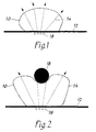
- an airbag 10 is shown, which is in the initial stage of Unfolding.
- the airbag 10 is supported on a vehicle part 12, for example the Instrument panel, from.
- On the inside of the airbag 10 there are four tether straps 14 attached, each wound on a coil 16 attached to the vehicle part 12 are.
- the tether has a certain length, which makes the shape of the inflated Airbags is set to a certain extent.
- Each of the four coils is 16 assigned a braking device (not shown) which takes effect as soon as the Pull-off speed of the relevant tether 14 drops.
- the coil 16 can, for example, be a braking device controlled by the centrifugal force be assigned, which takes effect as soon as the speed of the coil after a initial acceleration suddenly decreases.
- the airbag 10 If the airbag 10 is deployed on an object, for example a body part 18 of an occupant comes to rest, then he Area of the airbag prevented from further deployment. That means that at this area of the airbag 10, tether straps 14 no longer or only withdrawn from the associated coils 16 at a substantially lower speed become. This sudden decrease in the pulling speed of the tether 14 is determined by the corresponding measuring device and that of the associated one Brake device associated with coil 16 is activated to close the coil To block. The area of the airbag 10 which lies against the body part 18 can therefore not move further away from the vehicle part 12 because it is attacked by it Retain tether 14.
- the two can Deploy the outer areas of the airbag 10 further or remove them from the vehicle part 12, because the tether 14 attached to it from the associated coils 16 to can run to the specified length. 2 are the two outer ones The full length of the tether 14 is pulled off the associated coils 16.
- FIG. 3a, b and c is the timing of the unfolding process Embodiment of an airbag described above.
- the arrow indicates the gas flow through which the airbag 10 in the event of an accident is inflated.
- this area of the airbag is affected by the action of it Tether or the portion of the tether that engages it restrained, while the two outer areas of the airbag initially continue to develop unhindered until those attacking these areas
- the tether or sections of the tether are taut.
- a tether 24 is fastened, which is wound onto a spool 26 is.
- the coil 26 is seated on the output shaft of a vehicle part 12 attached electric motor 28, which is, for example, a stepper motor can act.
- the vehicle is equipped with sensors (not shown), which determine the position of the seats. Leave the measured values of these sensors Conclusions about the distance of the respective occupant from the assigned airbag to.
- sensors can also be provided, which are based on the weight address the occupant. The combination of the measured values on the position of the Seat and sensors responsive to the weight of the occupant leaves even more precise Conclusions about the distance between the occupants and the airbag receiving vehicle part.
- Sensors optical, capacitive, ultrasound, active and passive infrared are provided, which determine the position of the occupant and thus determine the distance to the vehicle part receiving the airbag.
- the measured values determined by the sensors are converted into a (not shown) preprogrammed calculator entered. Calculated based on the measured values received the computer calculates the distance between the occupant and the person receiving the airbag Vehicle part.
- the computer controls the electric motor 28 so that it the tether 24 winds up so far that only one corresponds to the calculated distance effective length remains.
- This adjustment of the effective length of the Tether 24 can either be permanent after the occupant is seated and has adjusted the seating position according to his wishes.
- an appropriately designed sensor for example an optical sensor, can also set the effective length of the tether continuously be performed. In this case, the effective length of the tether becomes constant readjusted as soon as the occupant changes his position, for example himself bends forward.
- FIG. 4a and b show the airbag 10 in the inflated state.
- Fig. 4a illustrates the case where the computer due to the from the sensors determined measured values a large distance between the occupant and the Vehicle part 12 has calculated. Therefore, only one of the electric motor 28 was used small length of the tether 24 wound on the spool 26.
- 6b shows the case where the computer based on the measured values determined by the sensors has calculated a small distance between the occupant and the vehicle part 12. The electric motor 28 therefore has a longer length of the tether 24 wound on the coil 26, so that its effective length compared to Fig. 4a was shortened.
- the airbag 10 When the airbag 10 is inflated, the airbag 10 consequently becomes inflated Retaining strap 24 held back in time before being excessive on the occupant Can exert forces.
Landscapes
- Engineering & Computer Science (AREA)
- Mechanical Engineering (AREA)
- Air Bags (AREA)
Claims (5)
- Airbag équipé, pour contrôler sa forme quand il est gonflé, d'au moins une bande de retenue en prise avec la face interne de l'airbag et, à l'état rentré, avec une partie du véhicule,
caractérisé en ce que
la bande de retenue (14) est enroulée sur une bobine (16) qui peut être fixée au véhicule (12) et la longueur de cette bande (14 ; 24) comprise entre les points d'attache à l'airbag (10) et à la bobine (16) peut varier et être ajustée automatiquement à la position de l'occupant à protéger. - Airbag selon la revendication 1,
caractérisé en ce que
la bobine (16) est associée à un dispositif de freinage qui intervient dès que la vitesse de tirage de la bande de retenue (14) s'effondre. - Airbag selon la revendication 2,
caractérisé en ce que
un dispositif optique de mesure détermine la vitesse de tirage de la bande de retenue. - Airbag selon la revendication 2,
caractérisé en ce que
un dispositif mécanique de mesure détermine la vitesse de tirage de la bande de retenue. - Airbag selon la revendication 1,
caractérisé en ce que
si le véhicule est équipé de capteurs donnant la position de l'occupant, à la bobine (26) est associé un entraíneur (28) qui peut être actionné en fonction des valeurs mesurées par les capteurs, de manière à régler la longueur active de la bande de retenue (24).
Applications Claiming Priority (2)
| Application Number | Priority Date | Filing Date | Title |
|---|---|---|---|
| DE19811616A DE19811616A1 (de) | 1998-03-17 | 1998-03-17 | Airbag mit Fangbändern |
| DE19811616 | 1998-03-17 |
Publications (2)
| Publication Number | Publication Date |
|---|---|
| EP0943499A1 EP0943499A1 (fr) | 1999-09-22 |
| EP0943499B1 true EP0943499B1 (fr) | 2002-05-02 |
Family
ID=7861225
Family Applications (1)
| Application Number | Title | Priority Date | Filing Date |
|---|---|---|---|
| EP99102515A Expired - Lifetime EP0943499B1 (fr) | 1998-03-17 | 1999-02-10 | Airbag avec bande de retenue |
Country Status (2)
| Country | Link |
|---|---|
| EP (1) | EP0943499B1 (fr) |
| DE (2) | DE19811616A1 (fr) |
Cited By (1)
| Publication number | Priority date | Publication date | Assignee | Title |
|---|---|---|---|---|
| US9027170B2 (en) | 2008-12-09 | 2015-05-12 | Dainese S.P.A. | Personal protection device and garment incorporating said device |
Families Citing this family (16)
| Publication number | Priority date | Publication date | Assignee | Title |
|---|---|---|---|---|
| US6513835B2 (en) * | 2001-03-26 | 2003-02-04 | General Motors Corporation | Automotive vehicle air bag system |
| US6869103B2 (en) * | 2002-12-13 | 2005-03-22 | Delphi Technologies, Inc. | Apparatus and method for controlling an inflatable cushion |
| US6793243B2 (en) * | 2003-02-06 | 2004-09-21 | Key Safety Systems, Inc. | Airbag deployment rate sensor with spool brake |
| US6840539B2 (en) * | 2003-02-21 | 2005-01-11 | Key Safety Systems, Inc. | Airbag and a deployment sensor |
| DE102005008653B4 (de) * | 2005-02-25 | 2008-09-25 | Daimler Ag | Gassack-Rückhaltesystem |
| DE102005048912A1 (de) * | 2005-02-25 | 2006-08-31 | Daimlerchrysler Ag | Gassack-Rückhaltesystem |
| DE102005037998A1 (de) * | 2005-02-25 | 2006-09-14 | Daimlerchrysler Ag | Gassack-Rückhaltesystem |
| DE102005028481B4 (de) * | 2005-06-20 | 2007-10-18 | Siemens Restraint Systems Gmbh | Airbagmodul |
| JP2007091112A (ja) * | 2005-09-29 | 2007-04-12 | Toyoda Gosei Co Ltd | エアバッグ装置 |
| US7484757B2 (en) | 2005-12-08 | 2009-02-03 | Gm Global Technology Operations, Inc. | Air bag with a supported channel |
| DE102007006668A1 (de) | 2007-02-10 | 2008-08-14 | Daimler Ag | Frontairbagvorrichtung für ein Kraftfahrzeug |
| ES2381709T3 (es) | 2008-12-09 | 2012-05-30 | Dainese S.P.A. | Prenda adaptada para asociarse a un dispositivo para la protección personal de un usuario |
| IT1392306B1 (it) * | 2008-12-09 | 2012-02-24 | Dainese Spa | Dispositivo di protezione personale ed indumento incorporante tale dispositivo. |
| DE102017101060A1 (de) | 2017-01-20 | 2018-07-26 | Trw Automotive Gmbh | Fangbandsteuerungsmodul und Gassackbaugruppe |
| DE102018003147A1 (de) | 2018-03-27 | 2018-09-27 | Daimler Ag | Airbagmodul |
| DE102023111323A1 (de) | 2023-05-02 | 2024-11-07 | Autoliv Development Ab | Fahrzeug mit einer Rückhaltevorrichtung |
Family Cites Families (6)
| Publication number | Priority date | Publication date | Assignee | Title |
|---|---|---|---|---|
| US5249825A (en) * | 1992-07-13 | 1993-10-05 | General Motors Corporation | Air bag with releasable tethers |
| US5308113A (en) * | 1992-10-09 | 1994-05-03 | Trw Vehicle Safety Systems Inc. | Airbag inflation-controlling member |
| US5280953A (en) * | 1992-11-25 | 1994-01-25 | General Motors Corporation | Displacement responsive air bag vent |
| GB2299550B (en) * | 1995-04-03 | 1998-06-24 | Autoliv Dev | Improvements in or relating to a safety arrangement |
| DE29707162U1 (de) * | 1997-04-14 | 1997-06-19 | Petri Ag | Gassack mit mindestens einem Fangband |
| DE29805217U1 (de) * | 1998-03-23 | 1998-07-30 | Trw Airbag Sys Gmbh & Co Kg | Fahrzeuginsassen-Rückhaltesystem |
-
1998
- 1998-03-17 DE DE19811616A patent/DE19811616A1/de not_active Withdrawn
-
1999
- 1999-02-10 DE DE59901330T patent/DE59901330D1/de not_active Expired - Fee Related
- 1999-02-10 EP EP99102515A patent/EP0943499B1/fr not_active Expired - Lifetime
Cited By (1)
| Publication number | Priority date | Publication date | Assignee | Title |
|---|---|---|---|---|
| US9027170B2 (en) | 2008-12-09 | 2015-05-12 | Dainese S.P.A. | Personal protection device and garment incorporating said device |
Also Published As
| Publication number | Publication date |
|---|---|
| DE59901330D1 (de) | 2002-06-06 |
| DE19811616A1 (de) | 1999-09-23 |
| EP0943499A1 (fr) | 1999-09-22 |
Similar Documents
| Publication | Publication Date | Title |
|---|---|---|
| EP0943499B1 (fr) | Airbag avec bande de retenue | |
| EP2144787B1 (fr) | Système d'assise d'un véhicule automobile et procédé de protection d'un passager | |
| DE69825698T2 (de) | Sicherheitsrückhaltesystem | |
| DE19956530B4 (de) | Sicherheitsgurtanordnung für ein Kraftfahrzeug | |
| DE69511335T2 (de) | Verfahren und Vorrichtung zum Erkennen eines entgegen der Fahrtrichtung ausgerichteten Kindersicherheitssitzes | |
| EP1417117A1 (fr) | Systeme d'airbag | |
| DE60035287T2 (de) | Luftsack-rückhaltesystem mit veränderlichem profil | |
| WO2009056309A2 (fr) | Système de protection pour passagers de véhicules, à soutien variable et procédé d'exploitation correspondant | |
| DE10123921C1 (de) | Insassenrückhaltesystem mit einer Gurtkraftbegrenzungsvorrichtung | |
| DE10020795A1 (de) | Gassack-Rückhaltesystem | |
| DE102007019315B4 (de) | Luftsacksystem | |
| WO2015120970A1 (fr) | Dispositif de protection des occupants d'un véhicule automobile et véhicule automobile | |
| EP0812741A1 (fr) | Dispositif de coussin gonflable dans un véhicule automobile | |
| DE19517440C2 (de) | Gurtaufroller und damit ausgerüstete Sicherheitseinrichtung für ein Kraftfahrzeug | |
| DE29805209U1 (de) | Aufprall-Schutzvorrichtung für Fahrzeuginsassen | |
| DE19837749A1 (de) | Airbagmodul mit Fangbändern | |
| DE60204890T2 (de) | Aufroller | |
| DE102018121810A1 (de) | Gurtlastmodulierung für fahrzeugfrontschrägaufpralle | |
| DE102006006807B4 (de) | Verfahren zur gesteuerten Ausgabe eines Gurtbandes eines Sicherheitsgurtsystems und entsprechendes Rückhaltesystem | |
| DE102017216180B4 (de) | Sicherheitsgurtanordnungen für ein Kraftfahrzeug | |
| DE10206755A1 (de) | Sicherheitsvorrichtung für ein Kraftfahrzeug | |
| DE102006021380A1 (de) | Fahrzeuginsassen-Sicherheitssystem und Verfahren zur Erkennung der Position eines Fahrzeuginsassen | |
| DE4417064A1 (de) | Rückhaltesystem mit Airbagsteuerung | |
| DE112004003030B4 (de) | Rückhaltevorrichtung für einen Insassen eines Fahrzeugs | |
| EP3917809B1 (fr) | Module de coussin gonflable pour un système de retenue d'occupant de véhicule ainsi que procédé pour faire fonctionner un système de retenue d'occupants de véhicule au moyen d'un tel module de coussin gonflable |
Legal Events
| Date | Code | Title | Description |
|---|---|---|---|
| PUAI | Public reference made under article 153(3) epc to a published international application that has entered the european phase |
Free format text: ORIGINAL CODE: 0009012 |
|
| 17P | Request for examination filed |
Effective date: 19990728 |
|
| AK | Designated contracting states |
Kind code of ref document: A1 Designated state(s): DE FR GB SE |
|
| AX | Request for extension of the european patent |
Free format text: AL;LT;LV;MK;RO;SI |
|
| 17Q | First examination report despatched |
Effective date: 20000417 |
|
| AKX | Designation fees paid |
Free format text: DE FR GB SE |
|
| GRAG | Despatch of communication of intention to grant |
Free format text: ORIGINAL CODE: EPIDOS AGRA |
|
| GRAG | Despatch of communication of intention to grant |
Free format text: ORIGINAL CODE: EPIDOS AGRA |
|
| GRAH | Despatch of communication of intention to grant a patent |
Free format text: ORIGINAL CODE: EPIDOS IGRA |
|
| REG | Reference to a national code |
Ref country code: GB Ref legal event code: IF02 |
|
| GRAH | Despatch of communication of intention to grant a patent |
Free format text: ORIGINAL CODE: EPIDOS IGRA |
|
| GRAA | (expected) grant |
Free format text: ORIGINAL CODE: 0009210 |
|
| AK | Designated contracting states |
Kind code of ref document: B1 Designated state(s): DE FR GB SE |
|
| REG | Reference to a national code |
Ref country code: GB Ref legal event code: FG4D Free format text: NOT ENGLISH |
|
| GBT | Gb: translation of ep patent filed (gb section 77(6)(a)/1977) |
Effective date: 20020502 |
|
| REF | Corresponds to: |
Ref document number: 59901330 Country of ref document: DE Date of ref document: 20020606 |
|
| ET | Fr: translation filed | ||
| PGFP | Annual fee paid to national office [announced via postgrant information from national office to epo] |
Ref country code: SE Payment date: 20030131 Year of fee payment: 5 |
|
| PGFP | Annual fee paid to national office [announced via postgrant information from national office to epo] |
Ref country code: GB Payment date: 20030206 Year of fee payment: 5 |
|
| PGFP | Annual fee paid to national office [announced via postgrant information from national office to epo] |
Ref country code: FR Payment date: 20030227 Year of fee payment: 5 |
|
| PLBE | No opposition filed within time limit |
Free format text: ORIGINAL CODE: 0009261 |
|
| STAA | Information on the status of an ep patent application or granted ep patent |
Free format text: STATUS: NO OPPOSITION FILED WITHIN TIME LIMIT |
|
| 26N | No opposition filed |
Effective date: 20030204 |
|
| PG25 | Lapsed in a contracting state [announced via postgrant information from national office to epo] |
Ref country code: DE Free format text: LAPSE BECAUSE OF NON-PAYMENT OF DUE FEES Effective date: 20030902 |
|
| PG25 | Lapsed in a contracting state [announced via postgrant information from national office to epo] |
Ref country code: GB Free format text: LAPSE BECAUSE OF NON-PAYMENT OF DUE FEES Effective date: 20040210 |
|
| PG25 | Lapsed in a contracting state [announced via postgrant information from national office to epo] |
Ref country code: SE Free format text: LAPSE BECAUSE OF NON-PAYMENT OF DUE FEES Effective date: 20040211 |
|
| EUG | Se: european patent has lapsed | ||
| GBPC | Gb: european patent ceased through non-payment of renewal fee |
Effective date: 20040210 |
|
| PG25 | Lapsed in a contracting state [announced via postgrant information from national office to epo] |
Ref country code: FR Free format text: LAPSE BECAUSE OF NON-PAYMENT OF DUE FEES Effective date: 20041029 |
|
| REG | Reference to a national code |
Ref country code: FR Ref legal event code: ST |