EP0943529A1 - Befestigungsvorrichtung für einen Längs-Traglenker eines hängenden Achsaggregates eines Fahrzeuges - Google Patents
Befestigungsvorrichtung für einen Längs-Traglenker eines hängenden Achsaggregates eines Fahrzeuges Download PDFInfo
- Publication number
- EP0943529A1 EP0943529A1 EP99200702A EP99200702A EP0943529A1 EP 0943529 A1 EP0943529 A1 EP 0943529A1 EP 99200702 A EP99200702 A EP 99200702A EP 99200702 A EP99200702 A EP 99200702A EP 0943529 A1 EP0943529 A1 EP 0943529A1
- Authority
- EP
- European Patent Office
- Prior art keywords
- support bracket
- fastening bolt
- supporting arm
- adjustment
- fastening
- Prior art date
- Legal status (The legal status is an assumption and is not a legal conclusion. Google has not performed a legal analysis and makes no representation as to the accuracy of the status listed.)
- Granted
Links
- 229910000831 Steel Inorganic materials 0.000 claims description 3
- 239000010959 steel Substances 0.000 claims description 3
- 239000000725 suspension Substances 0.000 description 5
- 239000006096 absorbing agent Substances 0.000 description 1
- 230000001419 dependent effect Effects 0.000 description 1
- 230000035939 shock Effects 0.000 description 1
Images


Classifications
-
- B—PERFORMING OPERATIONS; TRANSPORTING
- B60—VEHICLES IN GENERAL
- B60G—VEHICLE SUSPENSION ARRANGEMENTS
- B60G7/00—Pivoted suspension arms; Accessories thereof
- B60G7/02—Attaching arms to sprung part of vehicle
-
- B—PERFORMING OPERATIONS; TRANSPORTING
- B60—VEHICLES IN GENERAL
- B60G—VEHICLE SUSPENSION ARRANGEMENTS
- B60G11/00—Resilient suspensions characterised by arrangement, location or kind of springs
- B60G11/02—Resilient suspensions characterised by arrangement, location or kind of springs having leaf springs only
- B60G11/10—Resilient suspensions characterised by arrangement, location or kind of springs having leaf springs only characterised by means specially adapted for attaching the spring to axle or sprung part of the vehicle
- B60G11/12—Links, pins, or bushes
-
- B—PERFORMING OPERATIONS; TRANSPORTING
- B60—VEHICLES IN GENERAL
- B60G—VEHICLE SUSPENSION ARRANGEMENTS
- B60G11/00—Resilient suspensions characterised by arrangement, location or kind of springs
- B60G11/32—Resilient suspensions characterised by arrangement, location or kind of springs having springs of different kinds
- B60G11/34—Resilient suspensions characterised by arrangement, location or kind of springs having springs of different kinds including leaf springs
- B60G11/46—Resilient suspensions characterised by arrangement, location or kind of springs having springs of different kinds including leaf springs and also fluid springs
- B60G11/465—Resilient suspensions characterised by arrangement, location or kind of springs having springs of different kinds including leaf springs and also fluid springs with a flexible wall
-
- B—PERFORMING OPERATIONS; TRANSPORTING
- B62—LAND VEHICLES FOR TRAVELLING OTHERWISE THAN ON RAILS
- B62D—MOTOR VEHICLES; TRAILERS
- B62D17/00—Means on vehicles for adjusting camber, castor, or toe-in
-
- B—PERFORMING OPERATIONS; TRANSPORTING
- B60—VEHICLES IN GENERAL
- B60G—VEHICLE SUSPENSION ARRANGEMENTS
- B60G2200/00—Indexing codes relating to suspension types
- B60G2200/30—Rigid axle suspensions
- B60G2200/31—Rigid axle suspensions with two trailing arms rigidly connected to the axle
-
- B—PERFORMING OPERATIONS; TRANSPORTING
- B60—VEHICLES IN GENERAL
- B60G—VEHICLE SUSPENSION ARRANGEMENTS
- B60G2200/00—Indexing codes relating to suspension types
- B60G2200/40—Indexing codes relating to the wheels in the suspensions
- B60G2200/462—Toe-in/out
-
- B—PERFORMING OPERATIONS; TRANSPORTING
- B60—VEHICLES IN GENERAL
- B60G—VEHICLE SUSPENSION ARRANGEMENTS
- B60G2200/00—Indexing codes relating to suspension types
- B60G2200/40—Indexing codes relating to the wheels in the suspensions
- B60G2200/462—Toe-in/out
- B60G2200/4622—Alignment adjustment
-
- B—PERFORMING OPERATIONS; TRANSPORTING
- B60—VEHICLES IN GENERAL
- B60G—VEHICLE SUSPENSION ARRANGEMENTS
- B60G2202/00—Indexing codes relating to the type of spring, damper or actuator
- B60G2202/10—Type of spring
- B60G2202/11—Leaf spring
- B60G2202/112—Leaf spring longitudinally arranged
-
- B—PERFORMING OPERATIONS; TRANSPORTING
- B60—VEHICLES IN GENERAL
- B60G—VEHICLE SUSPENSION ARRANGEMENTS
- B60G2202/00—Indexing codes relating to the type of spring, damper or actuator
- B60G2202/10—Type of spring
- B60G2202/15—Fluid spring
- B60G2202/152—Pneumatic spring
-
- B—PERFORMING OPERATIONS; TRANSPORTING
- B60—VEHICLES IN GENERAL
- B60G—VEHICLE SUSPENSION ARRANGEMENTS
- B60G2204/00—Indexing codes related to suspensions per se or to auxiliary parts
- B60G2204/10—Mounting of suspension elements
- B60G2204/12—Mounting of springs or dampers
- B60G2204/128—Damper mount on vehicle body or chassis
-
- B—PERFORMING OPERATIONS; TRANSPORTING
- B60—VEHICLES IN GENERAL
- B60G—VEHICLE SUSPENSION ARRANGEMENTS
- B60G2204/00—Indexing codes related to suspensions per se or to auxiliary parts
- B60G2204/10—Mounting of suspension elements
- B60G2204/14—Mounting of suspension arms
- B60G2204/143—Mounting of suspension arms on the vehicle body or chassis
-
- B—PERFORMING OPERATIONS; TRANSPORTING
- B60—VEHICLES IN GENERAL
- B60G—VEHICLE SUSPENSION ARRANGEMENTS
- B60G2204/00—Indexing codes related to suspensions per se or to auxiliary parts
- B60G2204/40—Auxiliary suspension parts; Adjustment of suspensions
- B60G2204/41—Elastic mounts, e.g. bushings
-
- B—PERFORMING OPERATIONS; TRANSPORTING
- B60—VEHICLES IN GENERAL
- B60G—VEHICLE SUSPENSION ARRANGEMENTS
- B60G2204/00—Indexing codes related to suspensions per se or to auxiliary parts
- B60G2204/40—Auxiliary suspension parts; Adjustment of suspensions
- B60G2204/42—Joints with cam surfaces
-
- B—PERFORMING OPERATIONS; TRANSPORTING
- B60—VEHICLES IN GENERAL
- B60G—VEHICLE SUSPENSION ARRANGEMENTS
- B60G2204/00—Indexing codes related to suspensions per se or to auxiliary parts
- B60G2204/40—Auxiliary suspension parts; Adjustment of suspensions
- B60G2204/43—Fittings, brackets or knuckles
- B60G2204/4302—Fittings, brackets or knuckles for fixing suspension arm on the vehicle body or chassis
-
- B—PERFORMING OPERATIONS; TRANSPORTING
- B60—VEHICLES IN GENERAL
- B60G—VEHICLE SUSPENSION ARRANGEMENTS
- B60G2204/00—Indexing codes related to suspensions per se or to auxiliary parts
- B60G2204/40—Auxiliary suspension parts; Adjustment of suspensions
- B60G2204/44—Centering or positioning means
-
- B—PERFORMING OPERATIONS; TRANSPORTING
- B60—VEHICLES IN GENERAL
- B60G—VEHICLE SUSPENSION ARRANGEMENTS
- B60G2204/00—Indexing codes related to suspensions per se or to auxiliary parts
- B60G2204/40—Auxiliary suspension parts; Adjustment of suspensions
- B60G2204/44—Centering or positioning means
- B60G2204/4402—Spacers or shims
-
- B—PERFORMING OPERATIONS; TRANSPORTING
- B60—VEHICLES IN GENERAL
- B60G—VEHICLE SUSPENSION ARRANGEMENTS
- B60G2206/00—Indexing codes related to the manufacturing of suspensions: constructional features, the materials used, procedures or tools
- B60G2206/01—Constructional features of suspension elements, e.g. arms, dampers, springs
- B60G2206/60—Subframe construction
- B60G2206/601—Hanger bracket
Definitions
- the invention relates to a fastening device for a longitudinal supporting arm of a suspended axle unit of a vehicle, having a support bracket which is arranged on the underside of a vehicle chassis, is open towards the rear, as seen in the direction of travel, and has two side plates, the longitudinal supporting arm being mounted in the support bracket by means of a fastening bolt which extends in the transverse direction through the support bracket and fits through holes in the side plates of the support bracket, these holes being designed as slots which extend substantially in the direction of the longitudinal supporting arm, and adjustment means being provided for the purpose of adjusting the position of the fastening bolt in the slots.
- a fastening device of this type which offers the possibility of aligning an axle unit which is mounted under the vehicle, is known in various forms (cf. for example GB-A-2 257 670, EP-A-0 504 593 and DE-A-196 03 612).
- the adjustment means comprise a round disc with an eccentric hole through which the fastening bolt fits.
- the disc is arranged on the outside of the support bracket and, as seen in the direction of travel, at the front and rear sides is supported on a stop arranged on the support bracket. By rotating the eccentric disc, the position of the fastening bolt in the slots can be adjusted.
- the adjustment means comprise a displaceable rectangular plate which is arranged on the outside of the support bracket and, as seen in the direction of travel, at the front and rear sides is supported on an elongate stop arranged on the support bracket.
- the plate is provided with a slot through which the fastening bolt fits and which is at an angle to the vertical. By displacing the plate in the vertical direction, the position of the fastening bolt in the slots in the support bracket can be adjusted.
- the adjustment means comprise an eye bolt, the eye of which engages around the head of the fastening bolt and the threaded section of which fits through a hole in a plate part which projects sideways from the support bracket.
- a nut is arranged on the threaded section of the eye bolt on both sides of this plate part.
- the drawback of the known devices is that either the accuracy of the adjustment leaves something to be desired, as in the devices shown in GB-A-2 257 670, in which, when the nut of the fastening bolt is being tightened, the eccentric disc can begin to rotate with it, so that the position of the fastening bolt in the slots in the support bracket changes, or a relatively large number of components are required, as in the device shown in DE-A-196 03 612, while in all cases additional features, such as stops and projecting plate parts, have to be arranged on the support bracket.
- the object of the present invention is to provide a fastening device of the type mentioned in the preamble with which the position of the fastening bolt in the slots in the support bracket can be accurately adjusted using simple adjustment means.
- the adjustment means comprise at least one adjustment element which is provided with a hole through which the fastening bolt fits accurately, at the location of the fastening bolt can be displaced over a side plate of the support bracket only in substantially the longitudinal direction of the slot, and can be clamped fixedly to the side plate in question by means of the fastening bolt, and which adjustment element is arranged between a side plate of the support bracket and the longitudinal supporting arm, can pivot about a pivot point which lies at a certain distance above or below the fastening bolt and has a pivot axis which runs parallel to the fastening bolt, and on the underside projects beyond the support bracket.
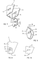
- Fig. 1 diagrammatically shows a wheel axle suspension of an axle unit of a vehicle.
- the wheel axle is denoted by the reference numeral 1.
- the wheel axle 1, on which one or more wheels are arranged at both ends, is illustrated as a hollow round axle. However, the wheel axle 1 may also be square or have some other cross section.
- the vehicle is usually provided with a wheel axle suspension on both sides.
- the wheel axle suspension comprises a support bracket 3 which is fastened to the chassis 2 of the vehicle and a supporting arm 4 for the wheel axle 1, which arm is fastened pivotably to the support bracket 3 and extends in the longitudinal direction of the vehicle.
- the wheel axle is fixed to the supporting arm 4 in a manner known per se, by means of a U-shaped clamp 5.
- the supporting arm 4 is fastened to the support bracket 3 by means of a fastening bolt 6.
- an end section 7 of the supporting arm 4 extends beyond the wheel axle 1.
- a pneumatic spring 8 is arranged between this end section 7 and the chassis 2.
- a shock absorber 9 is arranged between the supporting arm 4 and the support bracket 3.
- the support bracket 3 comprises two side plates 11 and 12, and the support bracket 3 is open towards the rear, as seen in the direction of travel.
- the fastening bolt 6 extends in the transverse direction through the support bracket 3 and fits through holes 13 and 14 in the side plates 11 and 12 of the support bracket 3.
- the holes 13 and 14 are designed as slots which extend substantially in the direction of the longitudinal supporting arm 4.
- the supporting arm 4 is bent round so as to form an eyelet 15.
- a bush 16 extends through this eyelet 15, a flexible (rubber) sleeve 17 being arranged between the bush 16 and the eyelet 15.
- the bush 16 projects slightly beyond the supporting arm 4.
- the bush 16 is clamped tight in the axial direction between the side plates 11 and 12 of the support bracket 3, by means of the fastening bolt 6 with nut 18.
- the flexibility of the sleeve 17 allows the supporting arm 4 to pivot slightly about the fixed bush 16.
- rings 20 and 21 are arranged on the outside of the support bracket 3, between the head 19 of the fastening bolt 6 and the side plate 11 of the support bracket 3, on the one hand, and between the nut 18 and the side plate 12 of the support bracket 3, on the other hand.
- An adjustment plate 23 which is provided with a hole 24 through which the fastening bolt 6 fits accurately is arranged between the side plate 11 of the support bracket 3 and the bush 16.
- the adjustment plate 23 has two functions, namely to transmit the clamping force provided by the fastening bolt 6 uniformly onto the bush 16, and secondly to adjust the position of the fastening bolt 6 in the slots 13 and 14 and therefore the position of the fastening point (pivot point) of the supporting arm 4 in the longitudinal direction of the vehicle. This adjustment is necessary in order to align the axle 1 of the vehicle.
- the adjustment plate 23 can pivot about a pivot point 25 which lies at a certain distance above the fastening bolt 6 and has a pivot axis which runs parallel to the fastening bolt 6. On the underside, the adjustment plate 23 projects beyond the support bracket 3.
- the pivot of the adjustment plate 23 may, for example, comprise a round pin 26 which is arranged on the adjustment plate 23 and engages in a hole 27 in the side wall 11 of the support bracket 3.
- the pin 26 which engages in the hole 27 has an additional advantage during assembly, since the adjustment plate 23 remains suspended from the pin 26.
- a second adjustment plate 23 may be arranged between the side plate 12 of the support bracket 3 and the bush 16. However, this is not strictly necessary. If a second adjustment plate 23 is not provided, a plate with a hole which fits around the fastening bolt 6 must be arranged between the side plate 12 of the support bracket 3 and the bush 16, in order to transmit the clamping force provided by the fastening bolt 6 uniformly onto the bush 16 on the side of the side plate 12 as well.
- a plate of this kind may be of simple design, such as the square plate 22 illustrated in Fig. 3. However, the plate may also have a different shape.
- the adjustment plate 23 may be of very simple design, while, on the other hand, the fastening point of the supporting arm 4 in the support bracket 3 can be adjusted very accurately.
- the pivot point 29 and 30, respectively, of the adjustment plate 23 may also be arranged beneath the slot 13.
- the pivot point of the adjustment plate 23 may also lie at the location of a bolt which is already present in the support bracket and is used to fasten another component of the wheel axle suspension. These designs are known to a person skilled in the art and are not shown in more detail here.
- the bolt which is already present then serves as a pivot pin.
- the shape of the adjustment plate 23 may differ from the shapes illustrated in the drawing.
- the adjustment plate 23 is preferably made from a hard steel grade which is able to withstand high surface pressures, since when a supporting arm 4 is mounted in support bracket 3 the surface pressure exerted by the bush 16 on the adjustment plate 23 may be extremely high. This, incidentally, also applies to other plates arranged between the bush 16 and the side plates 11 and 12, for example to the plate 22. Moreover, the adjustment plate 23 and the plate 22 function as wearing plates for the supporting arm 4, so that for this reason too the plates 23 and 22 should consist of a hard, wear-resistant steel grade.
- the fastening device may also be provided with a U-shaped adjustment bracket as the adjustment element, as illustrated diagrammatically in Figs. 7 to 10.
- Fig. 7 shows the bottom part of the support bracket 3 with slots 13 and 14, as well as a U-shaped adjustment bracket 31.
- the bracket 31 has two limbs 32 and 33 which are each provided with a hole 34 and 35, respectively, through which the fastening bolt 6 (not shown) can fit accurately.
- the adjustment bracket 31 engages around a side plate 11 or 12 of the support bracket 3, as shown in Fig. 8.
- connection piece 36 between the limbs 32 and 33 bears against the bottom edge of the side plate 11, so that the adjustment bracket cannot rotate, or can scarcely rotate, about the fastening bolt 6 in the mounted position.
- An adjustment bracket 31 may be arranged on one or both sides of the support bracket.
- the position of the fastening bolt 6 in the slots 13 and 14 is adjusted in more or less the same way as when an adjustment plate 23 is used.
- the position of the adjustment bracket 31, and therefore the position of the fastening bolt is adjusted by striking the adjustment bracket(s) 31 or the head 19 and/or the nut 18 of the fastening bolt 6 with a hammer. This moves the adjustment bracket 31 forwards or backwards.
- the nut 18 is tightened firmly with a predetermined torque.
- the adjustment bracket 31 does not rotate with the nut.
- the adjustment bracket 31 may be provided, on the top side, with a lip which is bent outwards and serves to prevent rotation of the (hexagonal) head of the fastening bolt 6.
- a lip of this kind is illustrated in dashed lines and is denoted by the reference numeral 41.
- Fig. 9 shows another embodiment of the U-shaped adjustment bracket 31.
- the limb 32 On the top side, the limb 32 has a cutout 37 in which a positioning projection 38 arranged on the support bracket 3 can engage.
- Fig. 10 shows the side plate 11 of the support bracket 3, this side plate being provided with a positioning projection 39 which is able to engage in a cutout 40 in the connection piece 36 of the U-shaped adjustment bracket 31.
Landscapes
- Engineering & Computer Science (AREA)
- Mechanical Engineering (AREA)
- Chemical & Material Sciences (AREA)
- Combustion & Propulsion (AREA)
- Transportation (AREA)
- Vehicle Body Suspensions (AREA)
Applications Claiming Priority (2)
| Application Number | Priority Date | Filing Date | Title |
|---|---|---|---|
| NL1008615 | 1998-03-17 | ||
| NL1008615A NL1008615C1 (nl) | 1998-03-17 | 1998-03-17 | Bevestigingsinrichting voor een langsdraagarm van een geveerd asstel van een voertuig. |
Publications (2)
| Publication Number | Publication Date |
|---|---|
| EP0943529A1 true EP0943529A1 (de) | 1999-09-22 |
| EP0943529B1 EP0943529B1 (de) | 2003-11-05 |
Family
ID=19766756
Family Applications (1)
| Application Number | Title | Priority Date | Filing Date |
|---|---|---|---|
| EP19990200702 Expired - Lifetime EP0943529B1 (de) | 1998-03-17 | 1999-03-10 | Befestigungsvorrichtung für einen Längs-Traglenker eines hängenden Achsaggregates eines Fahrzeuges |
Country Status (4)
| Country | Link |
|---|---|
| EP (1) | EP0943529B1 (de) |
| DE (1) | DE69912501T2 (de) |
| ES (1) | ES2210958T3 (de) |
| NL (1) | NL1008615C1 (de) |
Cited By (11)
| Publication number | Priority date | Publication date | Assignee | Title |
|---|---|---|---|---|
| EP1086836A1 (de) * | 1999-09-21 | 2001-03-28 | Weweler Nederland B.V. | Haltebock zur Befestigung einer Achsanordnung am Fahrzeugrahmen |
| NL1013173C2 (nl) * | 1999-09-29 | 2001-03-30 | Weweler Nv | Verbinding tussen een wielas van een voertuig en een de wielas dragende draagarm. |
| EP1088687A1 (de) * | 1999-09-29 | 2001-04-04 | Weweler Nederland B.V. | Verbindung zwischen einer Radachse eines Fahrzeugs und einem die Radachse tragenden Tragarm |
| WO2002090170A1 (en) * | 2001-05-04 | 2002-11-14 | The Holland Group, Inc. | Trailing beam suspension with alignment adjustment |
| EP1598260A1 (de) * | 2004-05-21 | 2005-11-23 | Audi Ag | Karosserieseitige Anlenkung eines Lenkers einer Radaufhängung eines Kraftfahrzeugs |
| EP2106934A1 (de) * | 2008-03-31 | 2009-10-07 | Weweler Nederland N.V. | Scharnieranordnung für eine Radachsenaufhängung |
| WO2011131444A1 (de) | 2010-04-21 | 2011-10-27 | Bombardier Transportation Gmbh | Anordnung zur temperierung von elektrischen komponenten in einem fahrzeug |
| EP2873596A1 (de) * | 2013-11-18 | 2015-05-20 | BPW Bergische Achsen KG | Achslift für eine Fahrzeugachse |
| CN108506395A (zh) * | 2017-02-24 | 2018-09-07 | 本田技研工业株式会社 | 板簧的托架结构 |
| EP3530497A1 (de) * | 2018-02-27 | 2019-08-28 | Autotech Engineering Deutschland GmbH | Fahrwerksbauteil mit exzenterscheibenanschlag sowie verfahren zur herstellung eines fahrwerksbauteils |
| EP4005834A1 (de) * | 2020-11-26 | 2022-06-01 | GIGANT GmbH | Fahrwerksaufhängung mit exzentrischem justierelement |
Families Citing this family (2)
| Publication number | Priority date | Publication date | Assignee | Title |
|---|---|---|---|---|
| CN115535124B (zh) * | 2022-10-08 | 2026-02-24 | 广东星际机车科技有限公司 | 一种三轮车的后桥总成 |
| DE102024002968A1 (de) * | 2024-09-13 | 2026-03-19 | Mercedes-Benz Group AG | Vorrichtung zum Einstellen eines radseitigen Sturzes am Querlenker eines Fahrzeugs |
Citations (9)
| Publication number | Priority date | Publication date | Assignee | Title |
|---|---|---|---|---|
| US3960388A (en) * | 1975-03-27 | 1976-06-01 | Lear Siegler, Inc. | Vehicle suspension system and alignment mechanism therefor |
| US4493493A (en) * | 1982-10-18 | 1985-01-15 | General Motors Corporation | Alignment adjustment apparatus for vehicle wheel suspension |
| US4650208A (en) * | 1984-12-26 | 1987-03-17 | Ford Motor Company | Indexable caster adjusting plate for motor vehicles |
| EP0230485A1 (de) * | 1984-07-20 | 1987-08-05 | Lear Siegler, Inc. | Radaufhängung eines Fahrzeugs |
| EP0450942A2 (de) * | 1990-04-05 | 1991-10-09 | Ror Rockwell Limited | Blockierungsmechanismus für ein Fahrzeug |
| EP0504593A1 (de) | 1991-03-20 | 1992-09-23 | Bergische Achsenfabrik Fr. Kotz & Söhne | Justiervorrichtung |
| GB2257670A (en) | 1991-07-18 | 1993-01-20 | Rubery Owen Rockwell Ltd | Vehicle tracking adjustment. |
| DE19603612A1 (de) | 1996-02-01 | 1997-03-20 | Krone Bernhard Gmbh Maschf | Aufhängung für Längslenker an gefederten Achsaggregaten |
| US5775719A (en) * | 1997-03-21 | 1998-07-07 | General Motors Corporation | Control arm alignment mechanism |
-
1998
- 1998-03-17 NL NL1008615A patent/NL1008615C1/nl not_active IP Right Cessation
-
1999
- 1999-03-10 EP EP19990200702 patent/EP0943529B1/de not_active Expired - Lifetime
- 1999-03-10 ES ES99200702T patent/ES2210958T3/es not_active Expired - Lifetime
- 1999-03-10 DE DE69912501T patent/DE69912501T2/de not_active Expired - Lifetime
Patent Citations (9)
| Publication number | Priority date | Publication date | Assignee | Title |
|---|---|---|---|---|
| US3960388A (en) * | 1975-03-27 | 1976-06-01 | Lear Siegler, Inc. | Vehicle suspension system and alignment mechanism therefor |
| US4493493A (en) * | 1982-10-18 | 1985-01-15 | General Motors Corporation | Alignment adjustment apparatus for vehicle wheel suspension |
| EP0230485A1 (de) * | 1984-07-20 | 1987-08-05 | Lear Siegler, Inc. | Radaufhängung eines Fahrzeugs |
| US4650208A (en) * | 1984-12-26 | 1987-03-17 | Ford Motor Company | Indexable caster adjusting plate for motor vehicles |
| EP0450942A2 (de) * | 1990-04-05 | 1991-10-09 | Ror Rockwell Limited | Blockierungsmechanismus für ein Fahrzeug |
| EP0504593A1 (de) | 1991-03-20 | 1992-09-23 | Bergische Achsenfabrik Fr. Kotz & Söhne | Justiervorrichtung |
| GB2257670A (en) | 1991-07-18 | 1993-01-20 | Rubery Owen Rockwell Ltd | Vehicle tracking adjustment. |
| DE19603612A1 (de) | 1996-02-01 | 1997-03-20 | Krone Bernhard Gmbh Maschf | Aufhängung für Längslenker an gefederten Achsaggregaten |
| US5775719A (en) * | 1997-03-21 | 1998-07-07 | General Motors Corporation | Control arm alignment mechanism |
Cited By (17)
| Publication number | Priority date | Publication date | Assignee | Title |
|---|---|---|---|---|
| EP1086836A1 (de) * | 1999-09-21 | 2001-03-28 | Weweler Nederland B.V. | Haltebock zur Befestigung einer Achsanordnung am Fahrzeugrahmen |
| NL1013173C2 (nl) * | 1999-09-29 | 2001-03-30 | Weweler Nv | Verbinding tussen een wielas van een voertuig en een de wielas dragende draagarm. |
| EP1088687A1 (de) * | 1999-09-29 | 2001-04-04 | Weweler Nederland B.V. | Verbindung zwischen einer Radachse eines Fahrzeugs und einem die Radachse tragenden Tragarm |
| WO2002090170A1 (en) * | 2001-05-04 | 2002-11-14 | The Holland Group, Inc. | Trailing beam suspension with alignment adjustment |
| US7210692B2 (en) | 2001-05-04 | 2007-05-01 | The Holland Group, Inc. | Trailing beam suspension with alignment adjustment |
| CN100361854C (zh) * | 2001-05-04 | 2008-01-16 | 霍兰集团公司 | 具有对准调整机构的尾梁悬架装置 |
| EP1598260A1 (de) * | 2004-05-21 | 2005-11-23 | Audi Ag | Karosserieseitige Anlenkung eines Lenkers einer Radaufhängung eines Kraftfahrzeugs |
| WO2009123437A1 (en) * | 2008-03-31 | 2009-10-08 | Weweler Nederland B.V. | Hinging arrangement for a wheel axle suspension |
| EP2106934A1 (de) * | 2008-03-31 | 2009-10-07 | Weweler Nederland N.V. | Scharnieranordnung für eine Radachsenaufhängung |
| US8448964B2 (en) | 2008-03-31 | 2013-05-28 | Vdl Weweler B.V. | Hinging arrangement for a wheel axle suspension |
| WO2011131444A1 (de) | 2010-04-21 | 2011-10-27 | Bombardier Transportation Gmbh | Anordnung zur temperierung von elektrischen komponenten in einem fahrzeug |
| EP2873596A1 (de) * | 2013-11-18 | 2015-05-20 | BPW Bergische Achsen KG | Achslift für eine Fahrzeugachse |
| CN108506395A (zh) * | 2017-02-24 | 2018-09-07 | 本田技研工业株式会社 | 板簧的托架结构 |
| CN108506395B (zh) * | 2017-02-24 | 2020-01-07 | 本田技研工业株式会社 | 板簧的托架结构 |
| EP3530497A1 (de) * | 2018-02-27 | 2019-08-28 | Autotech Engineering Deutschland GmbH | Fahrwerksbauteil mit exzenterscheibenanschlag sowie verfahren zur herstellung eines fahrwerksbauteils |
| US11285769B2 (en) | 2018-02-27 | 2022-03-29 | Autotech Engineering Deutschland GmbH | Chassis suspension component with eccentric disc stop and method for producing a chassis suspension component |
| EP4005834A1 (de) * | 2020-11-26 | 2022-06-01 | GIGANT GmbH | Fahrwerksaufhängung mit exzentrischem justierelement |
Also Published As
| Publication number | Publication date |
|---|---|
| ES2210958T3 (es) | 2004-07-01 |
| EP0943529B1 (de) | 2003-11-05 |
| DE69912501T2 (de) | 2004-09-23 |
| NL1008615C1 (nl) | 1999-09-20 |
| DE69912501D1 (de) | 2003-12-11 |
Similar Documents
| Publication | Publication Date | Title |
|---|---|---|
| US4033601A (en) | Adjustable hitch ball mount for a trailer hitch | |
| EP0230485B1 (de) | Radaufhängung eines Fahrzeugs | |
| US4695073A (en) | Toe and camber adjusting system | |
| EP0943529B1 (de) | Befestigungsvorrichtung für einen Längs-Traglenker eines hängenden Achsaggregates eines Fahrzeuges | |
| US5950971A (en) | Assembly for and method of mounting a suspension member to an axle housing | |
| US4577534A (en) | Front suspension alignment tool | |
| CA2082595C (en) | Alignment mechanism for vehicle suspensions | |
| EP0941915B1 (de) | Radachsenaufhängung für ein Fahrzeug mit pneumatischem Federungssystem | |
| EP1383672B1 (de) | Gezogener aufhängungslenker mit radausrichtungsjustierung | |
| US6478098B2 (en) | Adjustable apparatus and kit for a coupled snowmobile suspension | |
| US4552379A (en) | Compression link adaptor assembly | |
| US4117709A (en) | Camber adjusting tool | |
| CN104411462A (zh) | 具有通用夹紧台的弹簧夹紧装置 | |
| US4581802A (en) | Caster adjustment tool | |
| CA1185424A (en) | Wheel alignment device | |
| US6419247B1 (en) | Auxiliary axle assembly | |
| EP1273464B1 (de) | Verbindung zwischen einer starren Radachse eines Fahrzeugs und einem die Radachse tragenden Tragarm | |
| EP0816205A3 (de) | Lenksäuleneinheit für Fahrzeug | |
| EP3473457B1 (de) | Achslift | |
| US3788629A (en) | Vehicle traction bar | |
| GB2047642A (en) | Rear axle suspension of automotive vehicles | |
| US7360778B2 (en) | Traction device | |
| EP1580044A1 (de) | Verbindung zwischen einer Radachse eines Fahrzeugs und eines gezogenen diese Radachse tragenden Aufhängungslenkers | |
| US4388820A (en) | Camber correction tool | |
| US6260454B1 (en) | Wheel Alignment Tool |
Legal Events
| Date | Code | Title | Description |
|---|---|---|---|
| PUAI | Public reference made under article 153(3) epc to a published international application that has entered the european phase |
Free format text: ORIGINAL CODE: 0009012 |
|
| AK | Designated contracting states |
Kind code of ref document: A1 Designated state(s): BE DE ES FR GB IT NL |
|
| AX | Request for extension of the european patent |
Free format text: AL;LT;LV;MK;RO;SI |
|
| 17P | Request for examination filed |
Effective date: 20000316 |
|
| AKX | Designation fees paid |
Free format text: BE DE ES FR GB IT NL |
|
| 17Q | First examination report despatched |
Effective date: 20020320 |
|
| GRAH | Despatch of communication of intention to grant a patent |
Free format text: ORIGINAL CODE: EPIDOS IGRA |
|
| GRAS | Grant fee paid |
Free format text: ORIGINAL CODE: EPIDOSNIGR3 |
|
| GRAA | (expected) grant |
Free format text: ORIGINAL CODE: 0009210 |
|
| AK | Designated contracting states |
Kind code of ref document: B1 Designated state(s): BE DE ES FR GB IT NL |
|
| REG | Reference to a national code |
Ref country code: GB Ref legal event code: FG4D |
|
| REF | Corresponds to: |
Ref document number: 69912501 Country of ref document: DE Date of ref document: 20031211 Kind code of ref document: P |
|
| REG | Reference to a national code |
Ref country code: ES Ref legal event code: FG2A Ref document number: 2210958 Country of ref document: ES Kind code of ref document: T3 |
|
| ET | Fr: translation filed | ||
| PLBE | No opposition filed within time limit |
Free format text: ORIGINAL CODE: 0009261 |
|
| STAA | Information on the status of an ep patent application or granted ep patent |
Free format text: STATUS: NO OPPOSITION FILED WITHIN TIME LIMIT |
|
| 26N | No opposition filed |
Effective date: 20040806 |
|
| PGFP | Annual fee paid to national office [announced via postgrant information from national office to epo] |
Ref country code: NL Payment date: 20110331 Year of fee payment: 13 |
|
| PGFP | Annual fee paid to national office [announced via postgrant information from national office to epo] |
Ref country code: BE Payment date: 20110330 Year of fee payment: 13 |
|
| PGFP | Annual fee paid to national office [announced via postgrant information from national office to epo] |
Ref country code: IT Payment date: 20120327 Year of fee payment: 14 |
|
| BERE | Be: lapsed |
Owner name: *WEWELER NEDERLAND B.V. Effective date: 20120331 |
|
| REG | Reference to a national code |
Ref country code: NL Ref legal event code: V1 Effective date: 20121001 |
|
| PGFP | Annual fee paid to national office [announced via postgrant information from national office to epo] |
Ref country code: ES Payment date: 20120326 Year of fee payment: 14 |
|
| PG25 | Lapsed in a contracting state [announced via postgrant information from national office to epo] |
Ref country code: BE Free format text: LAPSE BECAUSE OF NON-PAYMENT OF DUE FEES Effective date: 20120331 |
|
| PG25 | Lapsed in a contracting state [announced via postgrant information from national office to epo] |
Ref country code: NL Free format text: LAPSE BECAUSE OF NON-PAYMENT OF DUE FEES Effective date: 20121001 |
|
| PGFP | Annual fee paid to national office [announced via postgrant information from national office to epo] |
Ref country code: GB Payment date: 20130226 Year of fee payment: 15 |
|
| PGFP | Annual fee paid to national office [announced via postgrant information from national office to epo] |
Ref country code: FR Payment date: 20130419 Year of fee payment: 15 |
|
| GBPC | Gb: european patent ceased through non-payment of renewal fee |
Effective date: 20140310 |
|
| REG | Reference to a national code |
Ref country code: FR Ref legal event code: ST Effective date: 20141128 |
|
| PG25 | Lapsed in a contracting state [announced via postgrant information from national office to epo] |
Ref country code: FR Free format text: LAPSE BECAUSE OF NON-PAYMENT OF DUE FEES Effective date: 20140331 Ref country code: GB Free format text: LAPSE BECAUSE OF NON-PAYMENT OF DUE FEES Effective date: 20140310 |
|
| PG25 | Lapsed in a contracting state [announced via postgrant information from national office to epo] |
Ref country code: IT Free format text: LAPSE BECAUSE OF NON-PAYMENT OF DUE FEES Effective date: 20140310 |
|
| REG | Reference to a national code |
Ref country code: ES Ref legal event code: FD2A Effective date: 20150427 |
|
| PG25 | Lapsed in a contracting state [announced via postgrant information from national office to epo] |
Ref country code: ES Free format text: LAPSE BECAUSE OF NON-PAYMENT OF DUE FEES Effective date: 20140311 |
|
| PGFP | Annual fee paid to national office [announced via postgrant information from national office to epo] |
Ref country code: DE Payment date: 20160324 Year of fee payment: 18 |
|
| REG | Reference to a national code |
Ref country code: DE Ref legal event code: R119 Ref document number: 69912501 Country of ref document: DE |
|
| PG25 | Lapsed in a contracting state [announced via postgrant information from national office to epo] |
Ref country code: DE Free format text: LAPSE BECAUSE OF NON-PAYMENT OF DUE FEES Effective date: 20171003 |