EP0943573A2 - Bobinoir pour fil continu - Google Patents
Bobinoir pour fil continu Download PDFInfo
- Publication number
- EP0943573A2 EP0943573A2 EP99102879A EP99102879A EP0943573A2 EP 0943573 A2 EP0943573 A2 EP 0943573A2 EP 99102879 A EP99102879 A EP 99102879A EP 99102879 A EP99102879 A EP 99102879A EP 0943573 A2 EP0943573 A2 EP 0943573A2
- Authority
- EP
- European Patent Office
- Prior art keywords
- yarn
- guide
- bobbin
- anchoring
- traverse device
- Prior art date
- Legal status (The legal status is an assumption and is not a legal conclusion. Google has not performed a legal analysis and makes no representation as to the accuracy of the status listed.)
- Granted
Links
- 238000004873 anchoring Methods 0.000 claims abstract description 44
- 238000004804 winding Methods 0.000 claims abstract description 27
- 238000012423 maintenance Methods 0.000 abstract description 5
- 230000008878 coupling Effects 0.000 description 4
- 238000010168 coupling process Methods 0.000 description 4
- 238000005859 coupling reaction Methods 0.000 description 4
- 230000007246 mechanism Effects 0.000 description 3
- 238000000034 method Methods 0.000 description 3
- 230000002452 interceptive effect Effects 0.000 description 2
- 238000012546 transfer Methods 0.000 description 2
- 230000015572 biosynthetic process Effects 0.000 description 1
- 230000003028 elevating effect Effects 0.000 description 1
- 238000004519 manufacturing process Methods 0.000 description 1
- 230000002265 prevention Effects 0.000 description 1
- 238000013404 process transfer Methods 0.000 description 1
- 238000000638 solvent extraction Methods 0.000 description 1
Images



Classifications
-
- B—PERFORMING OPERATIONS; TRANSPORTING
- B65—CONVEYING; PACKING; STORING; HANDLING THIN OR FILAMENTARY MATERIAL
- B65H—HANDLING THIN OR FILAMENTARY MATERIAL, e.g. SHEETS, WEBS, CABLES
- B65H65/00—Securing material to cores or formers
-
- B—PERFORMING OPERATIONS; TRANSPORTING
- B65—CONVEYING; PACKING; STORING; HANDLING THIN OR FILAMENTARY MATERIAL
- B65H—HANDLING THIN OR FILAMENTARY MATERIAL, e.g. SHEETS, WEBS, CABLES
- B65H67/00—Replacing or removing cores, receptacles, or completed packages at paying-out, winding, or depositing stations
- B65H67/04—Arrangements for removing completed take-up packages and or replacing by cores, formers, or empty receptacles at winding or depositing stations; Transferring material between adjacent full and empty take-up elements
- B65H67/044—Continuous winding apparatus for winding on two or more winding heads in succession
-
- B—PERFORMING OPERATIONS; TRANSPORTING
- B65—CONVEYING; PACKING; STORING; HANDLING THIN OR FILAMENTARY MATERIAL
- B65H—HANDLING THIN OR FILAMENTARY MATERIAL, e.g. SHEETS, WEBS, CABLES
- B65H67/00—Replacing or removing cores, receptacles, or completed packages at paying-out, winding, or depositing stations
- B65H67/04—Arrangements for removing completed take-up packages and or replacing by cores, formers, or empty receptacles at winding or depositing stations; Transferring material between adjacent full and empty take-up elements
- B65H67/044—Continuous winding apparatus for winding on two or more winding heads in succession
- B65H67/048—Continuous winding apparatus for winding on two or more winding heads in succession having winding heads arranged on rotary capstan head
-
- B—PERFORMING OPERATIONS; TRANSPORTING
- B65—CONVEYING; PACKING; STORING; HANDLING THIN OR FILAMENTARY MATERIAL
- B65H—HANDLING THIN OR FILAMENTARY MATERIAL, e.g. SHEETS, WEBS, CABLES
- B65H2701/00—Handled material; Storage means
- B65H2701/30—Handled filamentary material
- B65H2701/31—Textiles threads or artificial strands of filaments
Definitions
- the present invention relates to a filament yarn take-up winder for winding a filament yarn, and in particular, to an apparatus that operates when an operator guides the yarn onto an empty bobbin of the filament yarn take-up winder and when the yarn is transferred from a full package to an empty bobbin.
- a filament yarn take-up winder its body includes a turret plate having two bobbin holders protruding therefrom so that the turret plate rotates by 180 ° to switch the bobbin holders between a winding position and a standby position.
- a contact roller that contacts a bobbin installed on the bobbin holder is provided above the bobbin holder.
- a filament yarn spinned and continuously supplied is wound into a package while being traversed by a traverse device.
- this filament yarn take-up winder rotates the turret plate to switch an empty bobbin from the standby position to the winding position for winding while removing the full package moved at the standby position from the bobbin holder and passing the empty bobbin on the holder to set it in a standby condition, thereby allowing the yarn to be continuously wound.
- the winder In switching between the winding position and the standby position, the yarn leading to the full package must be transferred to the empty bobbin around which the yarn is to be wound.
- the winder includes a yarn-removal guide for removing the yarn from the traverse device, a yarn-shifting guide for moving the removed yarn to a yarn-catching grave position in the empty bobbin, and a yarn-anchoring guide for temporarily bearing the moved yarn before transferring it to the traverse device. These guides are used during a threading operation for initially installing the yarn on the empty bobbin, as well as during the operation for transferring the yarn from a full package to an empty package.
- the traverse device, the contact roller, the yarn-removal guide, the yarn-shifting guide, and the yarn-anchoring guide are arranged on both sides of the yarn path, resulting in difficult threading and maintenance operations.
- the present invention is a filament yarn take-up winder comprising a traverse device for traversing a continuously supplied yarn, a bobbin around which the yarn traversed by the traverse device is wound and that has a yarn engaging portion outside the winding width, a bobbin holder on which the bobbin is installed and that rotates the bobbin, a contact roller for applying a pressure to the bobbin, a yarn-removal guide for changing the position of the yarn so as to leaves the traverse device, a yarn-shifting guide for moving the yarn that has been removed by the yarn-removal guide to the yarn engaging portion, and a yarn-anchoring guide for temporarily bearing the yarn that has been moved by the yarn-shifting guide; the traverse device, the contact roller, the yarn-removal guide, the yarn-shifting guide, and the yarn-anchoring guide are biased to one side of a yarn path, and the yarn-shifting guide and the yarn-anchoring guide move forward and backward crossing the yarn path in
- the present invention is a filament yarn take-up winder wherein the yarn-shifting guide and the yarn-anchoring guide move forward and backward crossing the yarn path in the direction orthogonal to the traverse direction so as to capture the yarn, which is temporarily borne by the yarn-anchoring guide in a position that the yarn-shifting guide and the yarn-anchoring guide are biased to the traverse device side relative to the yarn path.
- the present invention is a filament yarn take-up winder wherein the yarn-shifting guide and the yarn-anchoring guides are linked with the yarn-removal guide so as to move forward and backward integrally with the yarn-removal guide.
- the present invention is a filament yarn take-up winder wherein the yarn-anchoring guide can adjust its position in the axial direction of the bobbin.
- a body 10 includes a rotatable turret plate 12 having two bobbin holders 11 that protrude from the turret plate 12 and that have a plurality of bobbins B passed thereon.
- the turret plate 12 rotates by 180 ° each time to switch a bobbin holder 11 between a winding position Wp and a standby position Sp.
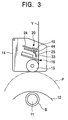
- a slide box 14 which ascends simultaneously as the packages P become larger and descends when empty bobbins B are switched from a standby position Sp to a winding position Wp, is arranged so that ascends and descends independently in the body 10.
- a contact roller 13 that rotates in contact with the bobbins B (the packages P), it is supported within the lower part of the slide box 14 in such a way that it can rotate independently.
- a blade type rotary traverse device 16 comprising two blades that rotate in relatively opposite directions is provided above the contact roller 13 in the slide box 14.
- the traverse device 16 and the contact roller 13 are arranged to one side of a yarn path for a continuously supplied yarn Y.
- An upper yarn guide apparatus 20 is located above the traverse device 16 in such a way as to be concentrated on the traverse device 16 side of the yarn Y.
- the body 10 includes a swinging arm 21 having a lower yarn guide apparatus 21a.
- the lower yarn guide apparatus 21a slides on the arm 21 and is composed of a yarn-drop prevention guide for preventing yarn being wound in a full package transferred to the standby position Sp from dropping onto the end of the layered yarn section of the full package when transferring the yarn, and a yarn-shift guide for aligning the yarn with a yarn-catching grave (a yarn-engaging section) formed in the empty bobbin.
- the traverse device 16, the upper yarn guide apparatus 20 and the lower yarn guide apparatus 21a are provided at every each yarn Y.
- 22 is a control board that allows take-up winding operation conditions to be set
- 23 is a partitioning cover.
- the turret plate 12 rotates by 180° to switch the bobbin holders 11 between the winding position Wp and the standby position Sp.
- the bobbin holder 11 at the winding position Wp is rotated while the contact roller 13 located above the bobbin holder 11 rotates in contact with the bobbins B (the packages P) to apply a predetermined pressure to the bobbins B.
- the traverse devices traverse a plurality of yarns Y spinned and continuously supplied as shown in Figure 7, while the yarns are wound into the packages P.
- the upper yarn guide apparatus 20 guides the yarn in such a way as to remove the yarn Y from the traverse device 16, move the removed yarn to a yarn-catching groove position in the empty bobbin B, and temporarily bear the yarn until it transfers to the traverse device 16 again.
- the upper yarn guide apparatus 20 will be described below.
- the upper yarn guide apparatus 20 is located in the slide box 14 in such a way as to be concentrated on one side of a yarn path (during package formation) together with the blade type rotary traverse device 16.
- This configuration precludes a relevant member from being located opposite to the yarn path (opposite to the side on which the traverse device 16 is installed, that is, the closing cover 14a side) when a closing cover 14a that covers the traverse device 16 in the slide box 14 is opened.
- the upper yarn guide apparatus 20 is composed of an inverse-V-shaped yarn-removal plate 25 which is provided so that can moved foward and backward on a supporting plate 24, a yarn-anchoring guide 44 that is provided on the yarn-removal plate 25 at a position corresponding to a yarn engaging portion S ( Figure 6) for the bobbin B and that is moved forward to a position where it can capture the yarn Y while the yarn-removal plate 25 is moving forward, and a yarn-shifting guide 45 that is provided on the yarn-removal guide 25 opposite to the yarn-anchoring guide 44 so as to move forward and backward in the traverse direction and that biases the yarn Y to the yarn engaging portion S of the bobbin B to engage it with the yarn-anchoring guide 44.
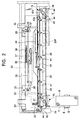
- the upper yarn guide apparatus 20 will be described in detail with reference to Figure 2.
- the supporting plate 24 is supported on a frame 30 of the slide box 14, and a yarn-removal plate 25 is provided below the supporting plate 24 so as to move on a pair of rails 32 forward and backward relative to the yarn path.
- the yarn-removal plate 25 has at its tip a yarn-removal guide 33 that has a circular cross section and that removes the yarn from the traverse device 16 (changing the position of the yarn path Y in such a way as to leave the traverse device 16).
- the yarn-removal plate 25 also has an opening 34 located at a position corresponding to the blade type rotary traverse device 16, which is described below.
- the yarn-removal plate 25 is linked with the supporting plate 24 via a pair of linking mechanisms 35, which are linked with a coupling rod 36, to which a moving cylinder 37 is coupled.
- a red 38 extends from the cylinder 37 to move the yarn-removal plate 25 forward, via the coupling rod 36 and the linking mechanisms 35, from the position shown by the continuous line in Figure 2 to a position 25P shown by the double chain-dotted line.
- the coupling rod 36 and the supporting plate 24 are coupled together via a spring 39 so that the spring force of the spring 39 returns the yarn-removal guide 25 from its extended position to its retracted position, which is shown by the continuous line in Figure 2.
- the yarn-removal guide 33 is configured as a bar common to all yarns and extending in the traverse direction.
- the yarn-removal guide 33 is located on the traverse device 16 side of the yarn Y at its standby position, and since it is coupled to the yarn-removal plate 25, when the yarn-removal plate 25 moves forward, the yarn-removal guide 33 is moved together with the yarn-removal plate 25 crossing the yarn in the direction orthogonal to the traverse direction, thereby separating the yarn Y from the traverse device 16.
- the blade type rotary traverse device 16 is arranged below the yarn-removal plate 25 and mounted on the frame 30 of the slide box 14.
- the traverse device 16 comprises a traverse guide member 40 that guides the yarn and defines a traverse range T, and two blades 42a and 42b that frequently appear on a yarn moving surface 41 of the traverse guide member 40 to move the yarn in the lateral direction.
- One blade 42a rotates counterclockwise in Figure 2, whereas the other blade 42b rotates clockwise, and the two blades 42a and 42b cross each other at the respective traverse ends to switch the traverse direction of the yarn.
- the yarn-removal plate 25 has L-shaped yarn-anchoring guides 44 at positions located out of the traverse range T and corresponding to the slits in the yarn engaging portions S in the bobbins B, wherein the number of guides are installed corresponds to the number of packages on which the yarn is wound.
- the yarn-anchoring guide 44 is located on the traverse device 16 side of the yarn Y at its standby position, and since it is coupled to the yarn-removal plate 25, when the yarn-removal plate 25 moves forward, the yarn-anchoring guide 44 is moved together with the yarn-removal plate 25 to move to a position where a yarn-engaging portion 44a (see Figure 6) beyond the yarn removed from the traverse device 16 by the yarn-removal guide 33.
- the position of the yarn-anchoring guide 44 can be fine-tuned in the axial direction of the bobbin B using a long hole 55, which is shown in Figure 6, and the tip of the yarn-engaging portion 44a is aligned with the traverse end.
- the yarn-engaging portion 44a temporarily bears the yarn Y.
- a yarn-shifting guide 45 is provided on the yarn-removal plate 25.
- the yarn-shifting guide 45 is opposed to the yarn-anchoring guide 44 and is normally located another outside of the traverse range T, while, in operation, moving toward the yarn-anchoring guide 44 to shift the yarn to a position of the yarn engaging portion S.
- the yarn-shifting guide 45 is provided on a rod-shaped upper guide 46 common to all yarns.
- the upper guide 46 can be moved in the axial direction of the bobbin using a guide rail 47 and can be moved back and forth in the traverse direction using a yarn-shifting cylinder 48 provided on the yarn-removal plate 25.
- the yarn-shifting guide 45 is located on the traverse device 16 side of the yarn Y at its standby position so as not to contact the yarn. Since, however, it is coupled to the yarn-removal plate 25, when the yarn-removal plate 25 moves forward, the guide 45 is moved together with the yarn-removal plate 25 to move to a position where it engages the yarn removed from the traverse device 16 by the yarn-removal guide 33.
- the yarn-removal plate 25 includes a proximity switch 50 for detecting the movement of the yarn-shifting guide 45 to the yarn-anchoring guide 44, and a detector 51 is mounted on the upper guide 46.
- the yarn Y spinned and continuously supplied as shown in Figures 1 and 7 is wound around the bobbin B at the winding position Wp into the package P while being traversed by the blade type rotary traverse device 16.
- the bobbin holder 11 at the winding position Wp is rotated, and the contact roller 13 is rotated while contacting the package P around which the yarn is being wound, thereby controlling the rotation of the bobbin holder 11 while elevating the slide box 14 as the winding diameter increases.
- the rod 38 of the moving cylinder 37 extends to move the coupling rod 36 leftward in Figure 2, thereby moving forwardly the yarn-removal guide 33 via the linking mechanisms 35 to the position 25P shown by the double chain-dotted line.
- the yarn Y remains within the traverse range T and between the yarn-anchoring guide 44 and the yarn-shifting guide 45.
- the proximity switch 50 described in Figure 2 operates to move the yarn-removal guide 33 backward to bend the yarn Y toward the traverse device 16 as shown in Figure 5. Then as shown in Figure6, while being caught between the yarn-shifting guide 45 and the yarn-anchoring guide 44, the yarn Y is pressed against and borne by the yarn-engaging portion 44a of the yarn-anchoring guide 44.
- a yarn-shift guide of the lower yarn guide apparatus 21a operates to catch the yarn Y in the yarn engaging portion S of the bobbin B, and the yarn leading to the full package P is cut by tension so as to be separated from the yarn Y leading to the empty bobbin B.
- the yarn-shifting cylinder 48 contracts to move the yarn-shifting guide 45 backward, the yarn Y moves simultaneously with the backward movement of the yarn-shifting guide 45 while sliding down the yarn-engaging portion 44a of the yarn-anchoring guide 44.
- the yarn-shifting guide 45 has been separated from the yarn-anchoring guide 44, the yarn is removed from the yarn-engaging portion 44a.
- the traverse device 16 immediately catches and traverses the yarn Y to wind it around the new bobbin B.
- the yarn-removal guide 33, the yarn-anchoring guide 44, and the yarn-shifting guide 45 are located on one side of the yarn path through normal winding process which the yarn is being wound normally (the yarn path shown in Figure 1), that is, the rear side of yarn path closer to the traverse device 16, whereas the opposite side, that is, the front side of the yarn path is an open space.
- the yarn path shown in Figure 1 that is, the rear side of yarn path closer to the traverse device 16
- the opposite side that is, the front side of the yarn path is an open space.
- the yarn-anchoring guide 44 has biased the yarn the traverse device 16 side relative to the yarn path through normal winding process, and the yarn-shifting guide 45 has been moved closer to the device 16 than to the yarn path. Consequently, when the yarn is removed from the yarn-anchoring guide 44 and traversed by the traverse device 16, the yarn and the yarn-shifting guide 45 are prevented from interfering with each other, thereby preventing the wound yarn from being damaged.
- the mounting position of the yarn-anchoring guide 44 can be fine-tuned in the axial direction of the yarn-removal guide 25 using the long hole 55, thereby enabling the forward and backward movements of the yarn-shifting guide 45 to be fine-tuned in the traverse direction.
- the range of a spiral portion can be fine-tuned that is formed when the process transfers to production winding after a bunch winding has been formed at the yarn engaging portion S.
- the spiral portion can thus be formed in such a way that it is easily cut later on.
- the yarn-anchoring guide 44 and the yarn-shifting guide 45 are adapted to move forward and backward together with the yarn-removal guide 33 in the direction orthogonal to the traverse direction, no means for driving the yarn-anchoring 44 or yarn-shifting guide 45 in this direction needs to be provided, thereby simplifying the control of the guide operations.
- the above embodiment provides the yarn-removal guide 33 in proximity to the traverse device 16, and this proximity helps make the machine more compact and makes it easier to fine-tune the yarn path.
- this box may be fixed in position while the turret plate rotates, which occurs as the diameter of the package increases.
- this apparatus is used not only to transfer the yarn from the full package to the empty bobbin as illustrated in the above embodiment but also to thread the yarn, it is applicable to a filament yarn take-up winder that are not based on the automatic switching method.
- the traverse device and the yarn-removal guide, etc. are concentrated on one side of the yarn path, and the other side is an open space.
- the present invention facilitates maintenance and threading operations.
- the yarn-shifting guide and the yarn-anchoring guide, etc. are located in such a way as to be completely biased to one side of the yarn path without crossing the yarn path, these guides, etc. are prevented from interfering with threading operations.
Landscapes
- Replacing, Conveying, And Pick-Finding For Filamentary Materials (AREA)
- Guides For Winding Or Rewinding, Or Guides For Filamentary Materials (AREA)
- Winding Filamentary Materials (AREA)
Applications Claiming Priority (2)
| Application Number | Priority Date | Filing Date | Title |
|---|---|---|---|
| JP7206898 | 1998-03-20 | ||
| JP07206898A JP3211766B2 (ja) | 1998-03-20 | 1998-03-20 | 紡糸巻取機 |
Publications (3)
| Publication Number | Publication Date |
|---|---|
| EP0943573A2 true EP0943573A2 (fr) | 1999-09-22 |
| EP0943573A3 EP0943573A3 (fr) | 2000-06-28 |
| EP0943573B1 EP0943573B1 (fr) | 2004-06-02 |
Family
ID=13478726
Family Applications (1)
| Application Number | Title | Priority Date | Filing Date |
|---|---|---|---|
| EP99102879A Expired - Lifetime EP0943573B1 (fr) | 1998-03-20 | 1999-03-03 | Bobinoir pour fil continu |
Country Status (6)
| Country | Link |
|---|---|
| EP (1) | EP0943573B1 (fr) |
| JP (1) | JP3211766B2 (fr) |
| KR (1) | KR100447521B1 (fr) |
| CN (1) | CN1136139C (fr) |
| DE (1) | DE69917702T2 (fr) |
| TW (1) | TW387857B (fr) |
Cited By (2)
| Publication number | Priority date | Publication date | Assignee | Title |
|---|---|---|---|---|
| KR100447521B1 (ko) * | 1998-03-20 | 2004-09-08 | 무라타 기카이 가부시키가이샤 | 방사권취기 |
| CN112678618A (zh) * | 2021-01-11 | 2021-04-20 | 蒙艳益 | 一种塑料管材用智能的自动化盘管设备 |
Families Citing this family (1)
| Publication number | Priority date | Publication date | Assignee | Title |
|---|---|---|---|---|
| JP5647563B2 (ja) * | 2011-05-11 | 2014-12-24 | Tmtマシナリー株式会社 | 糸条巻取機 |
Family Cites Families (9)
| Publication number | Priority date | Publication date | Assignee | Title |
|---|---|---|---|---|
| JPS5531757Y2 (fr) * | 1976-04-26 | 1980-07-29 | ||
| DE3132853A1 (de) * | 1981-08-20 | 1983-03-03 | Neumünstersche Maschinen- und Apparatebau GmbH (Neumag), 2350 Neumünster | Spulmaschine fuer automatische spulenwechsel |
| JPS59190164A (ja) * | 1983-04-11 | 1984-10-27 | Murata Mach Ltd | 糸条巻取機 |
| JPS60183472A (ja) * | 1984-03-02 | 1985-09-18 | Teijin Seiki Co Ltd | レボルビング型自動ワインダにおける糸掛け方法 |
| DE8916288U1 (de) * | 1988-12-22 | 1997-05-22 | Barmag Ag, 42897 Remscheid | Aufspulmaschine |
| DE4203196A1 (de) * | 1991-02-09 | 1992-08-13 | Barmag Barmer Maschf | Aufspulmaschine |
| KR970003444B1 (ko) * | 1993-07-15 | 1997-03-18 | 대우전자 주식회사 | 투사형 화상표시장치용 액츄에이터어레이의 실장방법 |
| JP3284806B2 (ja) * | 1995-01-18 | 2002-05-20 | 村田機械株式会社 | 巻取機のボビン位置制御方法 |
| JP3211766B2 (ja) * | 1998-03-20 | 2001-09-25 | 村田機械株式会社 | 紡糸巻取機 |
-
1998
- 1998-03-20 JP JP07206898A patent/JP3211766B2/ja not_active Expired - Fee Related
-
1999
- 1999-02-04 TW TW088101726A patent/TW387857B/zh not_active IP Right Cessation
- 1999-03-03 DE DE69917702T patent/DE69917702T2/de not_active Expired - Lifetime
- 1999-03-03 EP EP99102879A patent/EP0943573B1/fr not_active Expired - Lifetime
- 1999-03-18 KR KR10-1999-0009103A patent/KR100447521B1/ko not_active Expired - Lifetime
- 1999-03-19 CN CNB991030737A patent/CN1136139C/zh not_active Expired - Lifetime
Cited By (3)
| Publication number | Priority date | Publication date | Assignee | Title |
|---|---|---|---|---|
| KR100447521B1 (ko) * | 1998-03-20 | 2004-09-08 | 무라타 기카이 가부시키가이샤 | 방사권취기 |
| CN112678618A (zh) * | 2021-01-11 | 2021-04-20 | 蒙艳益 | 一种塑料管材用智能的自动化盘管设备 |
| CN112678618B (zh) * | 2021-01-11 | 2022-06-28 | 青岛睿杰塑料机械有限公司 | 一种塑料管材用智能的自动化盘管设备 |
Also Published As
| Publication number | Publication date |
|---|---|
| DE69917702D1 (de) | 2004-07-08 |
| EP0943573B1 (fr) | 2004-06-02 |
| JPH11268874A (ja) | 1999-10-05 |
| EP0943573A3 (fr) | 2000-06-28 |
| CN1229759A (zh) | 1999-09-29 |
| TW387857B (en) | 2000-04-21 |
| JP3211766B2 (ja) | 2001-09-25 |
| KR100447521B1 (ko) | 2004-09-08 |
| CN1136139C (zh) | 2004-01-28 |
| DE69917702T2 (de) | 2005-07-14 |
| KR19990077993A (ko) | 1999-10-25 |
Similar Documents
| Publication | Publication Date | Title |
|---|---|---|
| US4591105A (en) | Method and apparatus for automatically doffing and donning take-up packages on a winder | |
| US4638956A (en) | Textile machine for producing cross-wound bobbins | |
| EP0943573B1 (fr) | Bobinoir pour fil continu | |
| EP0927695B1 (fr) | Bobinoir pour fil élastique et bobine | |
| DE19827605A1 (de) | Verfahren und Vorrichtung zum Aufnehmen eines Fadenendes von der Oberfläche einer Kreuzspule | |
| US5318232A (en) | Method and apparatus for transferring a thread from a full package to an empty tube | |
| KR101213126B1 (ko) | 실 권취 장치 | |
| EP1065163B1 (fr) | Procédé pour former une réserve de fil | |
| EP1616829B1 (fr) | Guide-fil de bobineur automatique de type rotatif | |
| JP2000327228A (ja) | 巻取機の糸掛装置 | |
| CN116654719A (zh) | 丝线卷取机 | |
| JPH0717313B2 (ja) | 巻き取り機 | |
| CN116730105A (zh) | 丝线卷绕机 | |
| JPH0881134A (ja) | 糸移行システム | |
| KR100424985B1 (ko) | 방사권취기의 실전환방법 | |
| JP3209165B2 (ja) | 紡糸巻取機における糸掛け装置 | |
| JP2563121Y2 (ja) | 紡糸巻取機 | |
| JP2549004B2 (ja) | 糸条切り替え方法 | |
| JPS59223666A (ja) | 糸条巻取装置 | |
| JP2778465B2 (ja) | 紡糸巻取機 | |
| JPS644769Y2 (fr) | ||
| RU2078734C1 (ru) | Способ намотки химической нити | |
| JP3132416B2 (ja) | 紡糸巻取機及び紡糸巻取機の糸切り替え方法 | |
| JPH03186571A (ja) | 糸条巻取装置 | |
| JPS62171873A (ja) | 自動糸切替巻取機による糸切替方法 |
Legal Events
| Date | Code | Title | Description |
|---|---|---|---|
| PUAI | Public reference made under article 153(3) epc to a published international application that has entered the european phase |
Free format text: ORIGINAL CODE: 0009012 |
|
| AK | Designated contracting states |
Kind code of ref document: A2 Designated state(s): DE IT |
|
| AX | Request for extension of the european patent |
Free format text: AL;LT;LV;MK;RO;SI |
|
| PUAL | Search report despatched |
Free format text: ORIGINAL CODE: 0009013 |
|
| AK | Designated contracting states |
Kind code of ref document: A3 Designated state(s): AT BE CH CY DE DK ES FI FR GB GR IE IT LI LU MC NL PT SE |
|
| AX | Request for extension of the european patent |
Free format text: AL;LT;LV;MK;RO;SI |
|
| 17P | Request for examination filed |
Effective date: 20001214 |
|
| AKX | Designation fees paid |
Free format text: DE IT |
|
| 17Q | First examination report despatched |
Effective date: 20020828 |
|
| GRAP | Despatch of communication of intention to grant a patent |
Free format text: ORIGINAL CODE: EPIDOSNIGR1 |
|
| GRAS | Grant fee paid |
Free format text: ORIGINAL CODE: EPIDOSNIGR3 |
|
| GRAA | (expected) grant |
Free format text: ORIGINAL CODE: 0009210 |
|
| AK | Designated contracting states |
Kind code of ref document: B1 Designated state(s): DE IT |
|
| RBV | Designated contracting states (corrected) |
Designated state(s): DE |
|
| REF | Corresponds to: |
Ref document number: 69917702 Country of ref document: DE Date of ref document: 20040708 Kind code of ref document: P |
|
| PLBE | No opposition filed within time limit |
Free format text: ORIGINAL CODE: 0009261 |
|
| STAA | Information on the status of an ep patent application or granted ep patent |
Free format text: STATUS: NO OPPOSITION FILED WITHIN TIME LIMIT |
|
| 26N | No opposition filed |
Effective date: 20050303 |
|
| PGFP | Annual fee paid to national office [announced via postgrant information from national office to epo] |
Ref country code: DE Payment date: 20180322 Year of fee payment: 20 |
|
| REG | Reference to a national code |
Ref country code: DE Ref legal event code: R071 Ref document number: 69917702 Country of ref document: DE |