EP0943580A2 - Laterale Auslegerverriegelungsvorrichtung - Google Patents
Laterale Auslegerverriegelungsvorrichtung Download PDFInfo
- Publication number
- EP0943580A2 EP0943580A2 EP99102849A EP99102849A EP0943580A2 EP 0943580 A2 EP0943580 A2 EP 0943580A2 EP 99102849 A EP99102849 A EP 99102849A EP 99102849 A EP99102849 A EP 99102849A EP 0943580 A2 EP0943580 A2 EP 0943580A2
- Authority
- EP
- European Patent Office
- Prior art keywords
- locking
- set forth
- telescopic
- locking device
- pins
- Prior art date
- Legal status (The legal status is an assumption and is not a legal conclusion. Google has not performed a legal analysis and makes no representation as to the accuracy of the status listed.)
- Granted
Links
Images


Classifications
-
- B—PERFORMING OPERATIONS; TRANSPORTING
- B66—HOISTING; LIFTING; HAULING
- B66C—CRANES; LOAD-ENGAGING ELEMENTS OR DEVICES FOR CRANES, CAPSTANS, WINCHES, OR TACKLES
- B66C23/00—Cranes comprising essentially a beam, boom, or triangular structure acting as a cantilever and mounted for translatory of swinging movements in vertical or horizontal planes or a combination of such movements, e.g. jib-cranes, derricks, tower cranes
- B66C23/62—Constructional features or details
- B66C23/64—Jibs
- B66C23/70—Jibs constructed of sections adapted to be assembled to form jibs or various lengths
- B66C23/701—Jibs constructed of sections adapted to be assembled to form jibs or various lengths telescopic
- B66C23/708—Jibs constructed of sections adapted to be assembled to form jibs or various lengths telescopic locking devices for telescopic jibs
Definitions
- the present invention relates to a locking device for telescopic sections of a telescopic jib, and more particularly to the jib of a crane or mobile crane having such a locking device.
- Crane jib telescopic sections are lockable in the extended condition to, among other things, relieve the load on the telescoping system. This applies especially when use is made of entraining means, for example piston/cylinder units, for extending the telescopic sections in bringing one telescopic section after the other into the extended or retracted positions.
- entraining means for example piston/cylinder units
- EP O 661 213 A1 is a locking device for telescopic sections in which a locking pin guided in an inner telescopic section is able to engage a receiving portion in an outer telescopic section.
- This document describes the use of spring-biased locking pins in which the pin is maintained in a locked position by the force of a spring, whilst the inner end of the pin can be engaged by a hydraulic release device to return the pin into the released position in overcoming the force of a spring.
- a parallel description of the same design is described in U.S. Patent No. 5,628,416.
- each of a locking unit is arranged on each inner telescopic section so that they can be caused to engage with two oppositely located receiving portions in the vertical side webs of the outer telescopic section, i.e. preferably in the middle portion of the side webs.
- the special advantage afforded by the locking device in accordance with the invention is that the receiving portions and passages needed for the locking pins are disposed in a zone of the jib in which the bending load forces produce bending stresses in the jib of no significance.
- a maximum tensile stress occurs on the upper side of the profile and a maximum compressive stress materializes on the underside.
- the release device comprises a hydraulic actuating cylinder arranged on a piston/cylinder unit, more particularly on the head of the cylinder at the piston output end parallel to the longitudinal axis thereof.
- the aforementioned piston/cylinder unit serves to extend or retract the telescopic sections and is thus already provided with a hydraulic system.
- This hydraulic system can be made use of simultaneously to actuate the hydraulic actuating cylinder, which is arranged to advantage space-savingly parallel to the longitudinal axis of the piston/cylinder unit.
- the release device preferably comprises a lever, which converts the actuation of the hydraulic actuating cylinder so that an engaging end of the lever is moved substantially in the axial direction of the locking pins.
- the engaging end of the lever is preferably configured so that on axial travel of the piston/cylinder unit it can be brought into engagement with a clasp at the inner end of the locking pin.
- the engaging end of the lever advantageously comprises a T-shaped protuberance which can be brought into engagement with a longitudinally slotted clasp on the inner end of the locking pin, thus making it possible to bring this release device into the respective position suitable for releasing the locking pins by the method of the release device with the head of the piston/cylinder unit.
- the engaging end of the lever of the release device engages the inner clasp of the locking pin so that the locked position can be released when the hydraulic cylinder is set in motion. In this arrangement it needs to be assured that the jib sections are retained at all times either by means of the locking pins or are locked in place by an entraining device.
- the release device is arranged on the head of the piston/cylinder unit above an entraining device for extending the telescopic sections, the locking pins being located parallel to the entraining pins.
- the entraining device may be a conventional assembly having extensible entraining pins and receiving portions provided therefor in the telescopic sections.
- the outer end of the locking pins comprises a nose protruding opposite to the telescopic extension direction. In the locked condition of two sections the nose clasps the adjoining part of the receiving portion behind the outer wall of the outer section.
- a nose such as above permitting hook attachment to the outer telescopic section thus ensuring that the pin in the locked condition of two telescopic sections cannot be accidentally retracted has the advantage that when the lock is released, i.e. when the telescopic cylinder is extended somewhat with the inner section to enable the locking pin to be retracted there is no longer the danger of the pin snagging in the direction of telescopic extension or laterally in the receiving portion.
- a telescopic jib in accordance with the invention suitable for use, more particularly, on a crane and especially on a mobile crane; comprises a locking device as described above by the various embodiments.
- FIG. 1 there is illustrated the longitudinal section of a jib portion, namely the left hand portion as shown in Fig. 3 as seen from above, depicting the jib sections 1, 2, 3 and 4, which in this sequence make up the crane jib outside in.
- the locking device will now be discussed on the basis of the locking pin 10 used to lock the two outermost telescopic sections 1 and 2.
- the pin 10 is mounted axially shiftable in a housing 11 locked in place in the telescopic section 2. By its outer end 12 the pin 10 penetrates the outer telescopic section 1 through a receiving portion 5. To safeguard this locked condition the outer end 12 of the pin 10 features the nose 13 which hooks in place behind the outer wall of the section 1 in the locked condition.
- the pin 10 is shiftingly mounted in the housing 11, and it is biased by means of a spring 14 in the direction of the locked position, i.e. outwardly, whereby the spring is supported by an inner ridge on the pin 10 as well as by the inner face end of the housing 11 formed by a welded ring 11a serving to guide the pin 10 (see Fig. 4), i.e. by its inner end 15.
- the inner end 15 of the locking pin 10 penetrates the face end of the housing 11 inwardly, i.e. by a clasp 16 arranged at this location which will be detailed later with respect to Fig. 3.
- a piston/cylinder unit which, on the one hand, is used to retract or extend the telescopic sections by means of an entraining device (not shown) and, on the other, features at the end of the cylinder 30, where the piston 40 emerges, a head 31 on which a release device 20 to 25 is mounted for the locking pins 10.
- This release device consists of a hydraulic actuating cylinder 20 which can be powered via the hydraulic system of the piston/cylinder unit 40, 30.
- the hydraulic actuating cylinder 20 when called for by the working sequence and suitable positioning of all elements has been “seen” by the position monitor - the locking pin 10 is released via a system of levers which will now be detailed with respect to Fig. 2.
- This release device consists of an adjuster mechanism 21 which can be moved by means of the hydraulic actuating cylinder 20 in the direction as indicated by the upper double arrow B.
- the left-hand end of the adjuster mechanism 21 engages a lever 22, which can be pivoted about the pivot axis 23, which in turn is locked in place by the fastener 25.
- the adjuster mechanism 21 is formed by a threaded rod, the effective length of which can be varied.
- the axial movement (relative to the longitudinal axis of the jib) of the adjuster mechanism 21 is converted at the engaging end 24 of the lever 22 into a radial movement as indicated by the double arrow A.
- the engaging end 24 runs out in a T-shaped protuberance engaging the clasp 16 at the inner end 15 of the locking pin 10.
- the outer telescopic section 1 is divided on its left-hand side into the upper portion 1a, the middle portion 1b and the lower portion 1c.
- tensile forces become effective in the upper portion 1a of the side webs producing the highest tensile stress at the upper end, whereas in the lower portion 1c compressive forces are effective with a maximum at the lowermost point.
- the locking device has been placed in this portion so that the necessary material penetrations, for example the receiving portion 5, weaken the stability of the jib overall only to a negligible extent.
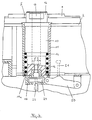
- the locking pin 10 biased in the housing 11 by the spring 14 is in turn to be seen, which passes through the outer telescopic section 1 at the receiving portion 5 by its outer end 12 and the nose 13.
- the inner end 15 of the pin 10 is evident, comprising at its innermost position a clasp 16 in which the engaging end 24 of the lever 22 resides, in the condition as shown, the lever 22 being actuated by the release device shown in detail in Fig. 2 via the hydraulic actuating cylinder 20. Due to the longitudinal slot 16a in the clasp 16 the engaging end 24 of the lever 22 is able to enter this clasp 16 in a direction perpendicular to the plane of the drawing in Fig. 3 (i.e. in the axial direction of the jib).
- the entraining device 60 (generally indicated in Fig. 3) comprises for example the receiving portions 62 provided in the inner telescopic section for the entraining pins 61 located in the head 31 of the piston/cylinder unit 30, the position of these components again being merely indicated by the broken lines.
- a emergency actuator for the locking pin 10 which in this case simply comprises a lever 50 engaging on one side the clasp 16 and on the other side a fixedly mounted lever 50.
- the lever 50 can be pivoted manually to the right, as a result of which the locking pin 10 can be released (manually) even if the hydraulics system has become inoperative.
- the lever prevents rotation of the pin 10 so that the engaging end 24 is always able to travel through the longitudinal slot 16a into the clasp 16.
- the locking action is sequenced as follows: Once, on extension of the telescopic section 2 by means of the entraining device 60 (i.e. the piston/cylinder unit 40, 30), the locking pin 10 has attained the position in which it is directly located at the receiving portion 5 in the outer telescopic section, pivoting the lever 22 via the hydraulic actuating cylinder 20 releases the movement of the pin 10 due to the spring bias 14, and the pin 10 moves outwardly by its outer end 12 into the receiving portion 5 and thus through the outer telescopic section 1. The inner telescopic section 2 can then be retracted somewhat so that the outer telescopic section 1 hooks into place with the nose 13 of the pin 10, it thereby being locked in place. The entraining device is then able to release and axially travel the telescopic section 2.
- the entraining device 60 i.e. the piston/cylinder unit 40, 30
- the lever 22 can be in turn pivoted via the hydraulic actuating cylinder 20 so that the engaging end 24 is strucked radially to the right (as shown in Fig. 3), entraining the pin 10 in its movement and shifting it into the unlocked position with the spring 14 compressed.
- the telescopic section 2 should be extended somewhat by the piston/cylinder unit 40, 30 to release the engagement of the nose 13.
- the individual locking components are each provided in duplicate to the left and right of the longitudinal center plane of the jib, i.e. on both the left and right release devices 20 to 25 and locking pins 10 as well as entraining units 60-62 are arranged.
Landscapes
- Engineering & Computer Science (AREA)
- Mechanical Engineering (AREA)
- Jib Cranes (AREA)
- Actuator (AREA)
Applications Claiming Priority (2)
| Application Number | Priority Date | Filing Date | Title |
|---|---|---|---|
| DE19811813 | 1998-03-18 | ||
| DE19811813A DE19811813B4 (de) | 1998-03-18 | 1998-03-18 | Seitliche Auslegerverriegelung |
Publications (3)
| Publication Number | Publication Date |
|---|---|
| EP0943580A2 true EP0943580A2 (de) | 1999-09-22 |
| EP0943580A3 EP0943580A3 (de) | 2000-07-05 |
| EP0943580B1 EP0943580B1 (de) | 2005-11-23 |
Family
ID=7861367
Family Applications (1)
| Application Number | Title | Priority Date | Filing Date |
|---|---|---|---|
| EP99102849A Expired - Lifetime EP0943580B1 (de) | 1998-03-18 | 1999-03-01 | Teleskopausleger mit Verriegelungsvorrichtung |
Country Status (7)
| Country | Link |
|---|---|
| US (1) | US6216895B1 (de) |
| EP (1) | EP0943580B1 (de) |
| JP (2) | JP2000086161A (de) |
| AT (1) | ATE310707T1 (de) |
| CA (1) | CA2265254C (de) |
| DE (2) | DE19811813B4 (de) |
| ES (1) | ES2252879T3 (de) |
Cited By (14)
| Publication number | Priority date | Publication date | Assignee | Title |
|---|---|---|---|---|
| JP2001278582A (ja) * | 2000-03-29 | 2001-10-10 | Tadano Ltd | 移動式クレーンのブーム伸縮機構 |
| GB2370558A (en) * | 2000-11-09 | 2002-07-03 | Siemens Ag | Telescopic jib with locking element |
| GB2369345B (en) * | 2000-09-21 | 2004-07-21 | Atecs Mannesmann Ag | Locking device |
| DE10048224B4 (de) * | 2000-09-21 | 2005-06-02 | Terex-Demag Gmbh & Co. Kg | Verriegelungseinheit für einen Teleskopausleger eines Krans |
| CN102180415A (zh) * | 2011-05-19 | 2011-09-14 | 三一汽车起重机械有限公司 | 一种伸缩臂及包括该伸缩臂的工程机械 |
| CN102275834A (zh) * | 2011-05-19 | 2011-12-14 | 三一汽车起重机械有限公司 | 一种伸缩臂及包括该伸缩臂的工程机械 |
| EP2465809A1 (de) * | 2010-12-17 | 2012-06-20 | Manitowoc Crane Group France SAS | Teleskopiersystem für Kranausleger und Zusatzausleger |
| CN102556858A (zh) * | 2011-12-30 | 2012-07-11 | 大连理工大学 | 采用齿条传动实现缸销同步运动的臂架插销机构 |
| CN102602824A (zh) * | 2012-03-02 | 2012-07-25 | 中联重科股份有限公司 | 一种吊臂电气感应装置及起重机 |
| CN105923555A (zh) * | 2016-05-12 | 2016-09-07 | 徐州重型机械有限公司 | 缸销臂销机械互锁装置、单缸插销伸缩系统和伸缩臂组件 |
| US10322915B2 (en) | 2013-08-09 | 2019-06-18 | Manitowoc Crane Group France Sas | Mechanical locking head |
| WO2019148390A1 (zh) * | 2018-01-31 | 2019-08-08 | 徐州重型机械有限公司 | 单缸插销式伸缩油缸、伸缩臂及工程机械设备 |
| EP3597584A1 (de) | 2018-07-20 | 2020-01-22 | Manitowoc Crane Group France SAS | Kranteleskop-verriegelungsvorrichtung |
| EP4541753A4 (de) * | 2022-06-17 | 2025-10-01 | Tadano Ltd | Arbeitsmaschine |
Families Citing this family (34)
| Publication number | Priority date | Publication date | Assignee | Title |
|---|---|---|---|---|
| EP1072554B1 (de) * | 1999-07-30 | 2004-03-17 | Liebherr-Werk Ehingen GmbH | Kran mit einem Teleskopausleger |
| FR2797862B1 (fr) * | 1999-09-01 | 2001-11-16 | Ppm | Procede de telescopage d'une fleche de grue, dispositif pour sa mise en oeuvre et fleche de grue en faisant application |
| DE10022373B4 (de) | 2000-05-08 | 2005-11-24 | Grove U.S. Llc | Verriegelungs- und Betätigungseinheit für seitliche Auslegerverriegelung |
| US6499612B1 (en) | 2001-07-27 | 2002-12-31 | Link-Belt Construction Equipment Co., L.P., Lllp | Telescoping boom assembly with rounded profile sections and interchangeable wear pads |
| US6601719B2 (en) | 2001-09-21 | 2003-08-05 | Link-Belt Construction Equipment Co., L.P., Lllp | Locking and latching system for a telescoping boom |
| US20030071004A1 (en) * | 2001-10-12 | 2003-04-17 | Higgins David J. | Extensible column |
| CN103183291A (zh) * | 2006-12-28 | 2013-07-03 | 中联重科股份有限公司 | 起重机用连杆式承载销插拔机构 |
| CN101214913B (zh) * | 2008-01-21 | 2010-06-02 | 长沙中联重工科技发展股份有限公司 | 一种起重机用连杆式互锁机构 |
| DE202008007906U1 (de) | 2008-06-16 | 2009-11-12 | Dr. Steffen Kaspar EMC GbR (vertretungsberechtigter Gesellschafter: Dr. Steffen Kaspar, 89597 Munderkingen) | Verriegelungsvorrichtung mit Rotorbetätigung zur Seite |
| DE202008007903U1 (de) | 2008-06-16 | 2010-02-11 | Kobelco Cranes Co., Ltd. | Verriegelungsvorrichtung mit Zylinderbetätigung zur Seite |
| DE102009009944B4 (de) * | 2009-02-20 | 2011-02-24 | Terex-Demag Gmbh | Sicherungs- und Verbolzungseinheit |
| JP5738977B2 (ja) * | 2010-04-01 | 2015-06-24 | パー システムズ, インコーポレイテッド | 張力トラスマスト |
| CN102424331B (zh) * | 2011-11-28 | 2013-08-07 | 中联重科股份有限公司 | 吊臂臂销机构及包含该臂销机构的起重设备 |
| CN102730578B (zh) * | 2012-06-27 | 2014-06-18 | 三一汽车起重机械有限公司 | 插拔销机构及其缸头、插销式伸缩臂和起重机 |
| US9834418B2 (en) | 2012-09-21 | 2017-12-05 | Par Systems, Inc. | Boat deployment assembly and method |
| CN102923586A (zh) * | 2012-11-13 | 2013-02-13 | 郑州新大方重工科技有限公司 | 伸缩式腹杆插销连接桁架结构 |
| JP5859467B2 (ja) | 2013-01-09 | 2016-02-10 | 株式会社ニフコ | ホールプラグ |
| US10494233B2 (en) | 2013-02-06 | 2019-12-03 | Par Systems, Llc | Relocatable fine motion positioner assembly on an overhead crane |
| DE102013011173B4 (de) * | 2013-07-04 | 2019-05-23 | Liebherr-Werk Ehingen Gmbh | Verfahren zur Montage eines Krans sowie Anlenkschuss, Teleskopausleger und Kran |
| JP6223071B2 (ja) * | 2013-08-30 | 2017-11-01 | 株式会社タダノ | クレーン装置のブーム伸縮機構 |
| DE202013010381U1 (de) | 2013-11-11 | 2013-11-26 | Terex Cranes Germany Gmbh | Antrieb einer Schiebekulisse eines Verriegelungssystems eines Teleskopiersystems eines Kranauslegers |
| EP3138805B1 (de) * | 2014-05-20 | 2020-08-05 | Xuzhou Heavy Machinery Co., Ltd. | Einzylinderbolzendehnvorrichtung und -kran |
| EP3448795B1 (de) * | 2016-04-25 | 2023-07-26 | Manitowoc Crane Companies, LLC | Kran mit drehbarem sperrmechanismus |
| US11111115B2 (en) | 2017-03-02 | 2021-09-07 | Maniitowoc Crane Companies, LLC | Wear pad with insert for telescoping boom assembly |
| EP3578500B1 (de) * | 2018-06-04 | 2022-07-20 | Manitowoc Crane Companies, LLC | Teleskopausleger mit rotierender verlängerung und verriegelungssystem |
| AU2019282610B2 (en) * | 2018-06-05 | 2023-01-19 | The Will-Burt Company | Auto-locking telescoping mast |
| IT201800020221A1 (it) * | 2018-12-19 | 2020-06-19 | Cifa Spa | Braccio telescopico per gru e gru comprendente tale braccio |
| CN109775585B (zh) * | 2019-03-19 | 2023-08-22 | 威海怡和专用设备制造有限公司 | 臂间锁紧装置 |
| CN113646251B (zh) * | 2019-04-04 | 2024-04-09 | 株式会社多田野 | 作业机 |
| CN111747324B (zh) * | 2020-07-09 | 2022-03-22 | 三一汽车起重机械有限公司 | 锁定机构、起重臂和起重机 |
| DE102020129762B3 (de) | 2020-11-11 | 2022-02-17 | Tadano Demag Gmbh | Teleskopausleger eines Mobilkrans |
| CN113697693A (zh) * | 2021-07-16 | 2021-11-26 | 中联重科股份有限公司 | 伸缩臂架及工程机械 |
| JP7662942B2 (ja) * | 2021-10-28 | 2025-04-16 | 株式会社タダノ | 作業機 |
| CN116354245B (zh) * | 2023-04-25 | 2025-05-13 | 浙江安居筑友科技有限公司 | 一种货运行车 |
Family Cites Families (18)
| Publication number | Priority date | Publication date | Assignee | Title |
|---|---|---|---|---|
| US2310887A (en) * | 1941-05-06 | 1943-02-09 | Armored Tank Corp | Hook-on-and-release mechanism for fighting tanks |
| FR2041329A5 (de) * | 1969-04-21 | 1971-01-29 | Ppm Sa | |
| US3692353A (en) * | 1970-07-21 | 1972-09-19 | Edward A Lynde | Safety lock assembly |
| GB1390469A (en) * | 1972-09-28 | 1975-04-16 | Gottwald Kg Leo | Telescopic crane jibs |
| US3921819A (en) * | 1974-07-26 | 1975-11-25 | Kidde & Co Walter | Boom latch mechanism |
| US4036372A (en) * | 1975-12-15 | 1977-07-19 | Clark Equipment Company | Extension and retraction means for the telescopic boom assembly of a crane |
| US4327533A (en) * | 1980-08-13 | 1982-05-04 | Kidde, Inc. | Crane boom extending, retracting and cooperative latching arrangement |
| SU1068377A1 (ru) * | 1981-10-02 | 1984-01-23 | Всесоюзный Научно-Исследовательский Институт По Монтажным И Специальным Строительным Работам | Телескопическа стрела грузоподъемного крана |
| US4433515A (en) * | 1981-11-04 | 1984-02-28 | Kidde, Inc. | Remotely operable latch and locking pin for a multi-section boom including a manual fly section |
| US4635805A (en) * | 1981-11-05 | 1987-01-13 | Kidde, Inc. | Crane boom locking pin insertion indicator and actuator means |
| SU1255555A1 (ru) * | 1985-01-28 | 1986-09-07 | Одесское производственное объединение тяжелого краностроения им.Январского восстания | Телескопическа стрела грузоподъемного устройства |
| DE3510710A1 (de) * | 1985-03-23 | 1986-10-02 | Fried. Krupp Gmbh, 4300 Essen | Teleskopkran |
| DE4018222A1 (de) * | 1990-06-07 | 1991-12-12 | Krupp Industrietech | Teleskopausleger mit kupplungsvorrichtung fuer ausschiebeanordnung |
| DE9013210U1 (de) * | 1990-09-18 | 1991-01-03 | Liebherr-Werk Ehingen Gmbh, 7930 Ehingen | Teleskopiersystem mit verringerter Knicklänge des Teleskopierzylinders |
| EP0499208B2 (de) * | 1991-02-11 | 2001-10-17 | LIEBHERR-WERK EHINGEN GmbH | Teleskopausleger für Fahrzeugkrane o.dgl. |
| DE4344795A1 (de) * | 1993-12-28 | 1995-06-29 | Liebherr Werk Ehingen | Fahrbarer Kran mit einem Teleskopausleger |
| US5537125A (en) * | 1994-09-29 | 1996-07-16 | Lba Technology, Inc. | Telescoping tower |
| DE19525642A1 (de) * | 1995-07-14 | 1997-01-16 | Krupp Ag Hoesch Krupp | Verriegelungs- und Betätigungszylinder für Teleskopausleger |
-
1998
- 1998-03-18 DE DE19811813A patent/DE19811813B4/de not_active Expired - Fee Related
-
1999
- 1999-03-01 EP EP99102849A patent/EP0943580B1/de not_active Expired - Lifetime
- 1999-03-01 ES ES99102849T patent/ES2252879T3/es not_active Expired - Lifetime
- 1999-03-01 DE DE69928462T patent/DE69928462T2/de not_active Expired - Lifetime
- 1999-03-01 AT AT99102849T patent/ATE310707T1/de not_active IP Right Cessation
- 1999-03-15 CA CA002265254A patent/CA2265254C/en not_active Expired - Fee Related
- 1999-03-17 JP JP11072075A patent/JP2000086161A/ja active Pending
- 1999-03-18 US US09/272,178 patent/US6216895B1/en not_active Expired - Lifetime
-
2006
- 2006-08-23 JP JP2006226623A patent/JP4409548B2/ja not_active Expired - Fee Related
Cited By (18)
| Publication number | Priority date | Publication date | Assignee | Title |
|---|---|---|---|---|
| JP2001278582A (ja) * | 2000-03-29 | 2001-10-10 | Tadano Ltd | 移動式クレーンのブーム伸縮機構 |
| GB2369345B (en) * | 2000-09-21 | 2004-07-21 | Atecs Mannesmann Ag | Locking device |
| DE10048224B4 (de) * | 2000-09-21 | 2005-06-02 | Terex-Demag Gmbh & Co. Kg | Verriegelungseinheit für einen Teleskopausleger eines Krans |
| GB2370558A (en) * | 2000-11-09 | 2002-07-03 | Siemens Ag | Telescopic jib with locking element |
| US8893905B2 (en) | 2010-12-17 | 2014-11-25 | Manitowoc Crane Group France Sas | Telescoping system for crane jib and auxiliary jib |
| EP2465809A1 (de) * | 2010-12-17 | 2012-06-20 | Manitowoc Crane Group France SAS | Teleskopiersystem für Kranausleger und Zusatzausleger |
| CN102180415A (zh) * | 2011-05-19 | 2011-09-14 | 三一汽车起重机械有限公司 | 一种伸缩臂及包括该伸缩臂的工程机械 |
| CN102275834A (zh) * | 2011-05-19 | 2011-12-14 | 三一汽车起重机械有限公司 | 一种伸缩臂及包括该伸缩臂的工程机械 |
| CN102180415B (zh) * | 2011-05-19 | 2013-04-03 | 三一汽车起重机械有限公司 | 一种伸缩臂及包括该伸缩臂的工程机械 |
| CN102556858A (zh) * | 2011-12-30 | 2012-07-11 | 大连理工大学 | 采用齿条传动实现缸销同步运动的臂架插销机构 |
| CN102602824A (zh) * | 2012-03-02 | 2012-07-25 | 中联重科股份有限公司 | 一种吊臂电气感应装置及起重机 |
| CN102602824B (zh) * | 2012-03-02 | 2013-11-06 | 中联重科股份有限公司 | 一种吊臂电气感应装置及起重机 |
| US10322915B2 (en) | 2013-08-09 | 2019-06-18 | Manitowoc Crane Group France Sas | Mechanical locking head |
| CN105923555A (zh) * | 2016-05-12 | 2016-09-07 | 徐州重型机械有限公司 | 缸销臂销机械互锁装置、单缸插销伸缩系统和伸缩臂组件 |
| CN105923555B (zh) * | 2016-05-12 | 2017-11-24 | 徐州重型机械有限公司 | 缸销臂销机械互锁装置、单缸插销伸缩系统和伸缩臂组件 |
| WO2019148390A1 (zh) * | 2018-01-31 | 2019-08-08 | 徐州重型机械有限公司 | 单缸插销式伸缩油缸、伸缩臂及工程机械设备 |
| EP3597584A1 (de) | 2018-07-20 | 2020-01-22 | Manitowoc Crane Group France SAS | Kranteleskop-verriegelungsvorrichtung |
| EP4541753A4 (de) * | 2022-06-17 | 2025-10-01 | Tadano Ltd | Arbeitsmaschine |
Also Published As
| Publication number | Publication date |
|---|---|
| CA2265254A1 (en) | 1999-09-18 |
| DE19811813A1 (de) | 1999-09-23 |
| DE69928462T2 (de) | 2006-08-10 |
| ATE310707T1 (de) | 2005-12-15 |
| DE19811813B4 (de) | 2005-11-24 |
| DE69928462D1 (de) | 2005-12-29 |
| EP0943580A3 (de) | 2000-07-05 |
| EP0943580B1 (de) | 2005-11-23 |
| JP4409548B2 (ja) | 2010-02-03 |
| CA2265254C (en) | 2006-10-24 |
| JP2006312558A (ja) | 2006-11-16 |
| ES2252879T3 (es) | 2006-05-16 |
| JP2000086161A (ja) | 2000-03-28 |
| US6216895B1 (en) | 2001-04-17 |
Similar Documents
| Publication | Publication Date | Title |
|---|---|---|
| EP0943580B1 (de) | Teleskopausleger mit Verriegelungsvorrichtung | |
| US6527131B1 (en) | Crane with a telescopic boom | |
| US5628416A (en) | Traveling crane with telescoping boom | |
| US6481587B2 (en) | Pendant-supported telescoping boom crane | |
| US5624046A (en) | Telescopic rods for a crane | |
| US3883170A (en) | Hoisting shackle with quick release attachment means | |
| US3658189A (en) | Hydraulic extensible boom structure | |
| EP2769954B1 (de) | Stiftziehgerät für Kranverbindungen | |
| CN104627863B (zh) | 起重机臂伸缩系统的锁止系统滑动连杆的驱动装置 | |
| US8893905B2 (en) | Telescoping system for crane jib and auxiliary jib | |
| US4688690A (en) | Method and apparatus for extending fly section of crane boom | |
| US20150041422A1 (en) | Mechanical locking head | |
| US4195873A (en) | Lifting device | |
| JP2000159483A (ja) | 移動式クレーンのブーム伸縮機構 | |
| EP0849212A1 (de) | Vorrichtung und Verfahren zum Arretieren von teleskopischen Auslegerteilen | |
| US3687323A (en) | Tower crane with telescopic jib | |
| US5465855A (en) | Telescoping crane arm | |
| EP0592135B1 (de) | Rückschlaghalteeinrichtung für Spitzenausleger | |
| US6206213B1 (en) | Crane with a luffing jib | |
| US4332094A (en) | Hydraulic locking of the boom to the swivel arm of an excavator, crane or the like | |
| US20030071005A1 (en) | Structural boom and pendant support | |
| CN110980555A (zh) | 一种起重机伸缩臂及起重机 | |
| EP3765397B1 (de) | Verstifteter teleskopkranausleger | |
| EP1055635B1 (de) | Kran mit Einem Teleskopausleger | |
| US20260138854A1 (en) | Crane and method |
Legal Events
| Date | Code | Title | Description |
|---|---|---|---|
| PUAI | Public reference made under article 153(3) epc to a published international application that has entered the european phase |
Free format text: ORIGINAL CODE: 0009012 |
|
| AK | Designated contracting states |
Kind code of ref document: A2 Designated state(s): AT CH DE ES FR GB IT LI NL |
|
| AX | Request for extension of the european patent |
Free format text: AL;LT;LV;MK;RO;SI |
|
| PUAL | Search report despatched |
Free format text: ORIGINAL CODE: 0009013 |
|
| AK | Designated contracting states |
Kind code of ref document: A3 Designated state(s): AT BE CH CY DE DK ES FI FR GB GR IE IT LI LU MC NL PT SE |
|
| AX | Request for extension of the european patent |
Free format text: AL;LT;LV;MK;RO;SI |
|
| RIC1 | Information provided on ipc code assigned before grant |
Free format text: 7B 66C 23/70 A, 7B 66C 23/693 B |
|
| 17P | Request for examination filed |
Effective date: 20001127 |
|
| AKX | Designation fees paid |
Free format text: AT CH DE ES FR GB IT LI NL |
|
| 17Q | First examination report despatched |
Effective date: 20040205 |
|
| GRAP | Despatch of communication of intention to grant a patent |
Free format text: ORIGINAL CODE: EPIDOSNIGR1 |
|
| RTI1 | Title (correction) |
Free format text: TELESCOPIC JIB WITH LOCKING DEVICE |
|
| GRAS | Grant fee paid |
Free format text: ORIGINAL CODE: EPIDOSNIGR3 |
|
| GRAA | (expected) grant |
Free format text: ORIGINAL CODE: 0009210 |
|
| AK | Designated contracting states |
Kind code of ref document: B1 Designated state(s): AT CH DE ES FR GB IT LI NL |
|
| PG25 | Lapsed in a contracting state [announced via postgrant information from national office to epo] |
Ref country code: NL Free format text: LAPSE BECAUSE OF FAILURE TO SUBMIT A TRANSLATION OF THE DESCRIPTION OR TO PAY THE FEE WITHIN THE PRESCRIBED TIME-LIMIT Effective date: 20051123 Ref country code: LI Free format text: LAPSE BECAUSE OF FAILURE TO SUBMIT A TRANSLATION OF THE DESCRIPTION OR TO PAY THE FEE WITHIN THE PRESCRIBED TIME-LIMIT Effective date: 20051123 Ref country code: CH Free format text: LAPSE BECAUSE OF FAILURE TO SUBMIT A TRANSLATION OF THE DESCRIPTION OR TO PAY THE FEE WITHIN THE PRESCRIBED TIME-LIMIT Effective date: 20051123 Ref country code: AT Free format text: LAPSE BECAUSE OF FAILURE TO SUBMIT A TRANSLATION OF THE DESCRIPTION OR TO PAY THE FEE WITHIN THE PRESCRIBED TIME-LIMIT Effective date: 20051123 |
|
| REG | Reference to a national code |
Ref country code: GB Ref legal event code: FG4D |
|
| RIN1 | Information on inventor provided before grant (corrected) |
Inventor name: RICHTER, FRANK Inventor name: ERDMANN, GERD |
|
| REG | Reference to a national code |
Ref country code: CH Ref legal event code: EP |
|
| REF | Corresponds to: |
Ref document number: 69928462 Country of ref document: DE Date of ref document: 20051229 Kind code of ref document: P |
|
| NLV1 | Nl: lapsed or annulled due to failure to fulfill the requirements of art. 29p and 29m of the patents act | ||
| REG | Reference to a national code |
Ref country code: ES Ref legal event code: FG2A Ref document number: 2252879 Country of ref document: ES Kind code of ref document: T3 |
|
| REG | Reference to a national code |
Ref country code: CH Ref legal event code: PL |
|
| ET | Fr: translation filed | ||
| PLBE | No opposition filed within time limit |
Free format text: ORIGINAL CODE: 0009261 |
|
| STAA | Information on the status of an ep patent application or granted ep patent |
Free format text: STATUS: NO OPPOSITION FILED WITHIN TIME LIMIT |
|
| 26N | No opposition filed |
Effective date: 20060824 |
|
| REG | Reference to a national code |
Ref country code: GB Ref legal event code: 732E Free format text: REGISTERED BETWEEN 20110915 AND 20110921 |
|
| REG | Reference to a national code |
Ref country code: FR Ref legal event code: TP Owner name: MANITOWOC CRANE GROUP FRANCE, FR Effective date: 20110920 |
|
| REG | Reference to a national code |
Ref country code: ES Ref legal event code: PC2A Owner name: MANITOWOC CRANE GROUP FRANCE SAS Effective date: 20111027 |
|
| REG | Reference to a national code |
Ref country code: DE Ref legal event code: R082 Ref document number: 69928462 Country of ref document: DE Representative=s name: SCHWABE SANDMAIR MARX, DE |
|
| PGFP | Annual fee paid to national office [announced via postgrant information from national office to epo] |
Ref country code: FR Payment date: 20120403 Year of fee payment: 14 |
|
| REG | Reference to a national code |
Ref country code: DE Ref legal event code: R082 Ref document number: 69928462 Country of ref document: DE Representative=s name: SCHWABE SANDMAIR MARX, DE Effective date: 20120330 Ref country code: DE Ref legal event code: R081 Ref document number: 69928462 Country of ref document: DE Owner name: MANITOWOC CRANE GROUP FRANCE SAS, FR Free format text: FORMER OWNER: GROVE U.S. LLC, SHADY GROVE, US Effective date: 20120330 |
|
| PGFP | Annual fee paid to national office [announced via postgrant information from national office to epo] |
Ref country code: DE Payment date: 20120323 Year of fee payment: 14 |
|
| PGFP | Annual fee paid to national office [announced via postgrant information from national office to epo] |
Ref country code: GB Payment date: 20120322 Year of fee payment: 14 |
|
| PGFP | Annual fee paid to national office [announced via postgrant information from national office to epo] |
Ref country code: IT Payment date: 20120330 Year of fee payment: 14 |
|
| PGFP | Annual fee paid to national office [announced via postgrant information from national office to epo] |
Ref country code: ES Payment date: 20120327 Year of fee payment: 14 |
|
| GBPC | Gb: european patent ceased through non-payment of renewal fee |
Effective date: 20130301 |
|
| REG | Reference to a national code |
Ref country code: FR Ref legal event code: ST Effective date: 20131129 |
|
| REG | Reference to a national code |
Ref country code: DE Ref legal event code: R119 Ref document number: 69928462 Country of ref document: DE Effective date: 20131001 |
|
| PG25 | Lapsed in a contracting state [announced via postgrant information from national office to epo] |
Ref country code: FR Free format text: LAPSE BECAUSE OF NON-PAYMENT OF DUE FEES Effective date: 20130402 Ref country code: DE Free format text: LAPSE BECAUSE OF NON-PAYMENT OF DUE FEES Effective date: 20131001 Ref country code: GB Free format text: LAPSE BECAUSE OF NON-PAYMENT OF DUE FEES Effective date: 20130301 |
|
| PG25 | Lapsed in a contracting state [announced via postgrant information from national office to epo] |
Ref country code: IT Free format text: LAPSE BECAUSE OF NON-PAYMENT OF DUE FEES Effective date: 20130301 |
|
| REG | Reference to a national code |
Ref country code: ES Ref legal event code: FD2A Effective date: 20150710 |
|
| PG25 | Lapsed in a contracting state [announced via postgrant information from national office to epo] |
Ref country code: ES Free format text: LAPSE BECAUSE OF NON-PAYMENT OF DUE FEES Effective date: 20130302 |