EP0943676A2 - Verfahren zur Verschlusskontrolle für Brut- und Trockenschränke sowie Brut- oder Trockenschrank - Google Patents
Verfahren zur Verschlusskontrolle für Brut- und Trockenschränke sowie Brut- oder Trockenschrank Download PDFInfo
- Publication number
- EP0943676A2 EP0943676A2 EP99100972A EP99100972A EP0943676A2 EP 0943676 A2 EP0943676 A2 EP 0943676A2 EP 99100972 A EP99100972 A EP 99100972A EP 99100972 A EP99100972 A EP 99100972A EP 0943676 A2 EP0943676 A2 EP 0943676A2
- Authority
- EP
- European Patent Office
- Prior art keywords
- locking
- closure element
- handle
- door
- inner door
- Prior art date
- Legal status (The legal status is an assumption and is not a legal conclusion. Google has not performed a legal analysis and makes no representation as to the accuracy of the status listed.)
- Granted
Links
Images


Classifications
-
- F—MECHANICAL ENGINEERING; LIGHTING; HEATING; WEAPONS; BLASTING
- F26—DRYING
- F26B—DRYING SOLID MATERIALS OR OBJECTS BY REMOVING LIQUID THEREFROM
- F26B25/00—Details of general application not covered by group F26B21/00 or F26B23/00
- F26B25/06—Chambers, containers, or receptacles
- F26B25/08—Parts thereof
- F26B25/12—Walls or sides; Doors
-
- B—PERFORMING OPERATIONS; TRANSPORTING
- B01—PHYSICAL OR CHEMICAL PROCESSES OR APPARATUS IN GENERAL
- B01L—CHEMICAL OR PHYSICAL LABORATORY APPARATUS FOR GENERAL USE
- B01L1/00—Enclosures; Chambers
- B01L1/02—Air-pressure chambers; Air-locks therefor
-
- C—CHEMISTRY; METALLURGY
- C12—BIOCHEMISTRY; BEER; SPIRITS; WINE; VINEGAR; MICROBIOLOGY; ENZYMOLOGY; MUTATION OR GENETIC ENGINEERING
- C12M—APPARATUS FOR ENZYMOLOGY OR MICROBIOLOGY; APPARATUS FOR CULTURING MICROORGANISMS FOR PRODUCING BIOMASS, FOR GROWING CELLS OR FOR OBTAINING FERMENTATION OR METABOLIC PRODUCTS, i.e. BIOREACTORS OR FERMENTERS
- C12M41/00—Means for regulation, monitoring, measurement or control, e.g. flow regulation
- C12M41/12—Means for regulation, monitoring, measurement or control, e.g. flow regulation of temperature
- C12M41/14—Incubators; Climatic chambers
-
- Y—GENERAL TAGGING OF NEW TECHNOLOGICAL DEVELOPMENTS; GENERAL TAGGING OF CROSS-SECTIONAL TECHNOLOGIES SPANNING OVER SEVERAL SECTIONS OF THE IPC; TECHNICAL SUBJECTS COVERED BY FORMER USPC CROSS-REFERENCE ART COLLECTIONS [XRACs] AND DIGESTS
- Y10—TECHNICAL SUBJECTS COVERED BY FORMER USPC
- Y10S—TECHNICAL SUBJECTS COVERED BY FORMER USPC CROSS-REFERENCE ART COLLECTIONS [XRACs] AND DIGESTS
- Y10S292/00—Closure fasteners
- Y10S292/21—Individually latched double doors
-
- Y—GENERAL TAGGING OF NEW TECHNOLOGICAL DEVELOPMENTS; GENERAL TAGGING OF CROSS-SECTIONAL TECHNOLOGIES SPANNING OVER SEVERAL SECTIONS OF THE IPC; TECHNICAL SUBJECTS COVERED BY FORMER USPC CROSS-REFERENCE ART COLLECTIONS [XRACs] AND DIGESTS
- Y10—TECHNICAL SUBJECTS COVERED BY FORMER USPC
- Y10T—TECHNICAL SUBJECTS COVERED BY FORMER US CLASSIFICATION
- Y10T74/00—Machine element or mechanism
- Y10T74/20—Control lever and linkage systems
- Y10T74/20576—Elements
- Y10T74/20582—Levers
-
- Y—GENERAL TAGGING OF NEW TECHNOLOGICAL DEVELOPMENTS; GENERAL TAGGING OF CROSS-SECTIONAL TECHNOLOGIES SPANNING OVER SEVERAL SECTIONS OF THE IPC; TECHNICAL SUBJECTS COVERED BY FORMER USPC CROSS-REFERENCE ART COLLECTIONS [XRACs] AND DIGESTS
- Y10—TECHNICAL SUBJECTS COVERED BY FORMER USPC
- Y10T—TECHNICAL SUBJECTS COVERED BY FORMER US CLASSIFICATION
- Y10T74/00—Machine element or mechanism
- Y10T74/20—Control lever and linkage systems
- Y10T74/20576—Elements
- Y10T74/20582—Levers
- Y10T74/20612—Hand
-
- Y—GENERAL TAGGING OF NEW TECHNOLOGICAL DEVELOPMENTS; GENERAL TAGGING OF CROSS-SECTIONAL TECHNOLOGIES SPANNING OVER SEVERAL SECTIONS OF THE IPC; TECHNICAL SUBJECTS COVERED BY FORMER USPC CROSS-REFERENCE ART COLLECTIONS [XRACs] AND DIGESTS
- Y10—TECHNICAL SUBJECTS COVERED BY FORMER USPC
- Y10T—TECHNICAL SUBJECTS COVERED BY FORMER US CLASSIFICATION
- Y10T74/00—Machine element or mechanism
- Y10T74/20—Control lever and linkage systems
- Y10T74/20576—Elements
- Y10T74/20732—Handles
-
- Y—GENERAL TAGGING OF NEW TECHNOLOGICAL DEVELOPMENTS; GENERAL TAGGING OF CROSS-SECTIONAL TECHNOLOGIES SPANNING OVER SEVERAL SECTIONS OF THE IPC; TECHNICAL SUBJECTS COVERED BY FORMER USPC CROSS-REFERENCE ART COLLECTIONS [XRACs] AND DIGESTS
- Y10—TECHNICAL SUBJECTS COVERED BY FORMER USPC
- Y10T—TECHNICAL SUBJECTS COVERED BY FORMER US CLASSIFICATION
- Y10T74/00—Machine element or mechanism
- Y10T74/20—Control lever and linkage systems
- Y10T74/20576—Elements
- Y10T74/20732—Handles
- Y10T74/20744—Hand crank
Definitions
- the invention relates to a method for the controlled closing of at least one inner door and an outer door of an incubator or drying cabinet and an incubator or drying cabinet.
- Such an incubator is for example from DE 29 24 446 C2 or US 4,336,329 known.
- an incubator with an outer door and one through inner door lockable treatment room known, being a control unit for control of heating elements is provided; the entrance of the control unit is with a door switch connected to the control of the outer door and a temperature sensor for the treatment room, where moisture and temperature distribution in the treatment room from the Control unit can be controlled.
- This arrangement also involves increased technical outlay required.
- the object of the invention is to provide a way to securely check the lock of the inner door to create drying or incubators, with the simplest possible design should be sought without increased technical effort.
- the object is achieved according to the method in that the side hinge in the opening area of the closet on its inner door pivoted about its axis Swing axis opposite side by means of a foldable handle rotatably mounted rigid locking tongue of a locking element by rotating the Tongue in a locking gap of a closure element is locked so far that the previously handle acting as a spacing element between the locking element and the outer door of the closure element and a previously existing blockage of the closure the outer door is lifted.
- a major advantage is the easy handling and simplified manufacture and Maintenance can be seen, since no complicated locking mechanisms and signal outputs are required here are.
- the inner door against a surrounding the opening in the usable space circumferential sealing element is pressed so that the usable space is closed atmospherically is observed from the outside, however, through the inner door, which is preferably constructed as a glass door can be.
- the task is for an incubator or drying cabinet with at least one arranged between usable space and outer door, in which both doors each are held by a side hinge rotatable about a vertical pivot axis, thereby solved that opposite to lock the inner door in the side front area of the cabinet the pivot axis is a closure element with an at least partially narrowing slot is provided as a locking gap, one with a foldable Handle-provided, rigid locking tongue rotatably mounted in the free swivel range of the inner door a locking element is arranged to engage, the handle in the Opening position of the inner door between the locking element and the outer door as a spacer acts and blocks the outer door from closing due to its support on the locking element, wherein the locking tongue engages in the slot as a locking gap by means of rotary movement can be guided within the slot until it stops so that the handle is outside the support area of the closure element and a blockage of the outer door prevented their closing.
- the incubator is rotatably arranged Handle designed as a foldable, spring-loaded spacer, the diametrical is arranged opposite the locking tongue; the grip surface closes with the plane the inner door approximately an angle of 70 °, both when open and with the inner door closed, pressing the outer door against the handle almost on you Angle is reduced in the range of 0 to 5 °; it proves to be particularly advantageous that no force from the outer door on the rotatable mounting of the tongue and handle can be exercised.
- the handle acts at least in part as a spacer located between the closure member and the outer door; in the locked The handle is approximately in a state of the locking tongue Level with the outer contour of the closure element.
- the double function of the handle with locking tongue has proven to be advantageous as a closing and control element.
- Re-opening the work space is by turning the handle clockwise possible.
- the inner door is made of transparent material, preferably Glass, so that the usable space is advantageously without atmospheric influences can be monitored optically from the outside.
- FIG. 1 shows the housing part 1 with the usable space 2 located therein, the frontal opening 3 of the usable space in its edge area from one directed to the front circumferential sealing element 4 is surrounded; the opening 3 is by means of hinges in the inner edge 6 held on the side edge region, which can be locked about a vertical axis 5 is pivotally arranged.
- the locking element 9 is in an opening (not visible here) of the free side edge the inner door 6 is rotatably supported about the axis of rotation 10, the handle 7 on a hub 11 being foldable is held; this ensures that by turning the handle 7 over a positive engagement in the hub 11 transmit the rotary motion to the locking tongue 8 becomes;
- the front opening 3 of housing part 1 by turning handle 7 counterclockwise Locking tongue 8 in the locking gap between the closure element 13 (inside) and the surface of the edge area is pressed.
- Handle 7 is in relation to Level of the inner door 6 in the angular range of about 3 to 70 ° can be folded over, with one here Helical spring not visible along the folding axis 12 an upward or upright movement the handle is made opposite the plane of the inner door 6; a sudden Stress caused by pressing when trying to close the outer door leads due to the bending the handle always to a closure of the angle from about 70 ° to about 3 °, so that at an attempted closing of the outer door pivotably arranged about a vertical axis 15 16 handle 7 is folded into a position of approximately 3 °; this comes handle 7 on the To lie outer contour of the closure element 13 so that the handle 7 as a spacer between Closure element 13 and the inner contour of the outer door 16 acts. That way occurs always a load on the closure element 13 or the foldable handle 7 while the bearing remains unloaded along the axis of rotation 10 of the inner door 6. So it is ensures that accidental closing of the outer door does not cause any damage inside door if it is not locked.
- the housing part 1 of the fumigation incubator or drying cabinet can be seen from FIG Opening 3 through inner door 6 - preferably made of transparent material, such as Glass, and Exterior door 16 can be closed.
- the inner door 6 and outer door 16 are shown here in the open state, the inner door 6 being pivotally mounted in the hinges 18 and 19 about the axis 5, while outer door 16 is rotatably mounted with its hinges about pivot axis 15.
- the inner forest the outer door 16 is designated by number 24.
- Inner door 6 is on the swivel axis 5 opposite side edge provided with a locking element 9, which with the help the rigid rotatable locking tongue 8 in the closure element 13 on the side edge of the housing part 1 is arranged lockable.
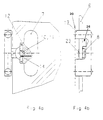
- Figure 3a shows a rigid locking tongue when the inner door 6 is open 8 of the locking element 9 arranged rotatably along axis 10 above, while the associated handle 7 is arranged around a perpendicular to the axis of rotation 10 Axis 12 can be folded down, but by positive engagement between the handle and the hub 11 rigidly connected to locking tongue 8, the rotary movement of the locking tongue 8 is guaranteed at all times by means of a handle.
- the handle 7 comes on the outwardly facing surface of the closure element 13 to lie, so that according to Figure 3b, the handle 7 as a spacer intermediate Closure element 13 and the inner wall 24 of the outer door 16 acts.
- a closing of the outer door 16 is not possible because its inner wall 24 acts as a spacer acting handle 7, which in turn on the outer surface or outer contour of the closure element 13 comes to rest and thus an intended closing operation locks by means of outer door 4; this means that a magnetic closure part of the outer door can not come into contact with the counterpart located in the housing part 1, so that the magnetic circuit of the closure cannot be closed.
- the locking tongue 8 is counterclockwise by 90 ° to the outside rotated so that they are in the narrowing or sloping locking gap 26 of the closure element 13 is pressed in the direction of the usable space, with rotation of the Handle 7 about the axis of rotation 10 in the tangential direction for the pivoting movement of the inner door 6 this is also moved in the direction of the usable space and after folding with its outer surface against the spring pressure approximately in the same plane as the closure element 13 lies. It is thus ensured that the effect of the Handle 7 has been lost as a spacer element and thus closure element 13 directly the inner wall 24 of the outer door 16 adjoins FIG. 2. Thus, after locking and the loss of the function of the spacer element of handle 7 also secure the outer door 16 be closed, which would not be possible with the inner door 6 unlocked.
Landscapes
- Chemical & Material Sciences (AREA)
- Engineering & Computer Science (AREA)
- Health & Medical Sciences (AREA)
- Life Sciences & Earth Sciences (AREA)
- Organic Chemistry (AREA)
- Zoology (AREA)
- General Engineering & Computer Science (AREA)
- Wood Science & Technology (AREA)
- Bioinformatics & Cheminformatics (AREA)
- Mechanical Engineering (AREA)
- Physics & Mathematics (AREA)
- Thermal Sciences (AREA)
- Biomedical Technology (AREA)
- Biotechnology (AREA)
- Microbiology (AREA)
- Sustainable Development (AREA)
- Analytical Chemistry (AREA)
- Chemical Kinetics & Catalysis (AREA)
- Biochemistry (AREA)
- General Health & Medical Sciences (AREA)
- Genetics & Genomics (AREA)
- Clinical Laboratory Science (AREA)
- Accommodation For Nursing Or Treatment Tables (AREA)
Abstract
Description
Claims (8)
- Verfahren zum kontrollierten Verschließen wenigstens einer Innentür und einer Außentür eines Brut- oder Trockenschrankes, dadurch gekennzeichnet, daß die mittels seitlichem Scharnier im Öffnungsbereich des Schrankes um Achse (5) schwenkbar gehaltene Innentür (6) auf ihrer der Achse (5) gegenüberliegenden Seite mittels einer mit klappbarem Handgriff (7) versehenen, drehbar gelagerten starren Verschluß-Zunge (8) eines Verriegelungselements (9) durch Drehung der Zunge in einen Arretierungsspalt (26) eines Verschlußelements (13) soweit verriegelt wird, daß der zuvor als Distanzelement zwischen Verschlußelement und Außentür wirkende Handgriff (7) den Auflagebereich des Verschlußelements verläßt und eine zuvor bestehende Blockade zwischen Außentür und Verschlußelement aufgehoben wird.
- Verfahren nach Anspruch 1, dadurch gekennzeichnet, daß beim Einschwenken der Verriegelungs-Zunge (8) in das Verschlußelement (13) diese zusammen mit der Innentür (6) durch einen sich in Verriegelungsrichtung verengenden Arretierungsspalt (26) im Verschlußelement (13) in Richtung Nutzraum gepreßt wird.
- Brut- oder Trocken-Schrank mit wenigstens einer zwischen Nutzraum und Außentür angeordneten Innentür, wobei beide Türen jeweils durch ein seitliches Scharnier um eine vertikale Schwenk-Achse drehbar gehalten sind, dadurch gekennzeichnet, daß zur Verriegelung der Innentür (6) im seitlichen Frontbereich eines Schrank-Gehäuseteils (1) gegenüberliegend der Schwenkachse (5) ein Verschlußelement (13) mit einem sich wenigstens teilsweise verengenden Schlitz als Arretierungsspalt vorgesehen ist, in den eine mit umklappbarem Handgriff (7) versehene, im freien Schwenkbereich der Innentür (6) drehbar gelagerte Verriegelungs-Zunge (8) eines Verriegelungselements (9) eingreifbar angeordnet ist, wobei der Handgriff (7) in der Öffnungsposition der Innentür (6) zwischen Verschlußelement (13) und Innenseite der Außentür als Distanzelement wirkt und ein Schließen der Außentür blockiert, wobei die Verriegelungs-Zunge (8) bei Eingriff in den Schlitz als Arretierungsspalt (26) mittels Drehbewegung bis zum Anschlag innerhalb des Schlitzes so führbar ist, daß sich der Handgriff (7) außerhalb des Auflagebereichs des Verschlußelements (13) befindet und eine Blockade der Außentür (16) bei ihrem Schließvorgang verhindert.
- Schrank nach Anspruch 3, dadurch gekennzeichnet, daß der Handgriff (7) als umklappbares, federbelastetes Distanzelement ausgebildet ist, das diametral gegenüber der Verriegelungs-Zunge (8) angeordnet ist.
- Schrank nach Anspruch 4, dadurch gekennzeichnet, daß der Handgriff (7) im entriegelten Zustand der Verriegelungs-Zunge (8) wenigstens zum Teil als ein zwischen dem Verschlußelement (13) und der Außentür (4) befindliches Distanzelement wirkt.
- Schrank nach Anspruch 4, dadurch gekennzeichnet, daß im verriegelten Zustand der Verriegelungs-Zunge (8) der Handgriff (7) sich in einer Ebene mit dem Verschlußelement (13) befindet.
- Schrank nach einem der Ansprüche 3 bis 6, dadurch gekennzeichnet, daß die Innentür (6) einen transparenten Werkstoff aufweist.
- Schrank nach Anspruch 7, dadurch gekennzeichnet, daß der transparente Werkstoff der Innentür (6) Glas ist.
Applications Claiming Priority (2)
| Application Number | Priority Date | Filing Date | Title |
|---|---|---|---|
| DE19803601 | 1998-01-30 | ||
| DE19803601A DE19803601C1 (de) | 1998-01-30 | 1998-01-30 | Verfahren zur Verschlußkontrolle für Brut- und Trockenschränke sowie Brut- oder Trockenschrank |
Publications (3)
| Publication Number | Publication Date |
|---|---|
| EP0943676A2 true EP0943676A2 (de) | 1999-09-22 |
| EP0943676A3 EP0943676A3 (de) | 2004-09-15 |
| EP0943676B1 EP0943676B1 (de) | 2005-12-21 |
Family
ID=7856136
Family Applications (1)
| Application Number | Title | Priority Date | Filing Date |
|---|---|---|---|
| EP99100972A Expired - Lifetime EP0943676B1 (de) | 1998-01-30 | 1999-01-21 | Verfahren zur Verschlusskontrolle für Brut- und Trockenschränke sowie Brut- oder Trockenschrank |
Country Status (3)
| Country | Link |
|---|---|
| US (1) | US6120119A (de) |
| EP (1) | EP0943676B1 (de) |
| DE (2) | DE19803601C1 (de) |
Cited By (1)
| Publication number | Priority date | Publication date | Assignee | Title |
|---|---|---|---|---|
| US9234369B2 (en) | 2012-03-21 | 2016-01-12 | Carrier Corporation | Furnace door latch assembly |
Families Citing this family (10)
| Publication number | Priority date | Publication date | Assignee | Title |
|---|---|---|---|---|
| DE10106349C2 (de) * | 2001-02-09 | 2003-09-18 | Kendro Lab Prod Gmbh | Verfahren zur Befeuchtung eines Nutzraumes in einem Brutschrank sowie Begasungs-Brutschrank |
| JP4243163B2 (ja) * | 2003-10-21 | 2009-03-25 | 三洋電機株式会社 | 低温貯蔵庫 |
| US7720558B2 (en) | 2004-09-04 | 2010-05-18 | Applied Materials, Inc. | Methods and apparatus for mapping carrier contents |
| US20070221340A1 (en) * | 2006-03-21 | 2007-09-27 | Maldas Company | RV door |
| US8759084B2 (en) | 2010-01-22 | 2014-06-24 | Michael J. Nichols | Self-sterilizing automated incubator |
| DE102017109262A1 (de) * | 2017-04-28 | 2018-10-31 | Binder Gmbh | Laborschrank |
| DE102017109263B4 (de) * | 2017-04-28 | 2019-06-06 | Binder Gmbh | Laborschrank |
| EP3539420A1 (de) | 2018-03-16 | 2019-09-18 | Eppendorf AG | Laborschrankvorrichtung zum lagern von laborproben mit magnetverschluss |
| US11906170B2 (en) * | 2019-04-29 | 2024-02-20 | Winston Industries, Llc | Magnetic positioning hinge for horizontal door assembly |
| EP4116715A4 (de) * | 2020-03-05 | 2024-04-03 | Hitachi High-Tech Corporation | Automatische analysevorrichtung |
Family Cites Families (9)
| Publication number | Priority date | Publication date | Assignee | Title |
|---|---|---|---|---|
| US506387A (en) * | 1893-10-10 | bahlsen | ||
| US1382837A (en) * | 1921-02-15 | 1921-06-28 | Jurek Martin | Refrigerator-door |
| GB280855A (en) * | 1926-11-22 | 1928-05-10 | Dook Heng Lau | Improvements in or relating to advertising devices |
| GB379890A (en) * | 1931-10-09 | 1932-09-08 | William Henry Davy | Improvements in catches for gate latches or the like |
| DE2924446C2 (de) * | 1979-06-18 | 1982-09-16 | W.C. Heraeus Gmbh, 6450 Hanau | Verfahren und Vorrichtung zum Kultivieren von Zellen und Geweben von Menschen und Tieren oder von Mikroorganismen |
| FR2596094B1 (fr) * | 1986-03-18 | 1991-12-06 | Jouan | Systeme de detection de la fermeture imparfaite des portes d'une enceinte a portes multiples |
| US4706478A (en) * | 1986-04-11 | 1987-11-17 | The Eastern Company | Rotary handle operated door lock |
| GB2196050B (en) * | 1986-09-24 | 1990-11-21 | Gkn Crompton | Fastner for securing frames together |
| JP3197696B2 (ja) * | 1993-07-22 | 2001-08-13 | 三洋電機株式会社 | 培養装置 |
-
1998
- 1998-01-30 DE DE19803601A patent/DE19803601C1/de not_active Expired - Fee Related
-
1999
- 1999-01-21 DE DE59912938T patent/DE59912938D1/de not_active Expired - Lifetime
- 1999-01-21 EP EP99100972A patent/EP0943676B1/de not_active Expired - Lifetime
- 1999-01-29 US US09/240,530 patent/US6120119A/en not_active Expired - Lifetime
Cited By (1)
| Publication number | Priority date | Publication date | Assignee | Title |
|---|---|---|---|---|
| US9234369B2 (en) | 2012-03-21 | 2016-01-12 | Carrier Corporation | Furnace door latch assembly |
Also Published As
| Publication number | Publication date |
|---|---|
| DE59912938D1 (de) | 2006-01-26 |
| EP0943676B1 (de) | 2005-12-21 |
| EP0943676A3 (de) | 2004-09-15 |
| US6120119A (en) | 2000-09-19 |
| DE19803601C1 (de) | 1999-09-09 |
Similar Documents
| Publication | Publication Date | Title |
|---|---|---|
| EP2147178B1 (de) | Scharnieranordnung | |
| EP1587701B1 (de) | Schwenkschiebetür für fahrzeuge | |
| DE60214458T2 (de) | Mechanische Betätigungsvorrichtung für ein mehrfach verstellbares Fenster | |
| EP2929764B1 (de) | Kasten mit gelenkeinrichtung | |
| EP0943676B1 (de) | Verfahren zur Verschlusskontrolle für Brut- und Trockenschränke sowie Brut- oder Trockenschrank | |
| DE19725677C2 (de) | Fenster oder Tür an Wohnwagen, Wohnmobilen oder sonstigen Fahrzeugen, mit Verriegelungseinrichtungen mit gemeinsamer Betätigungshandhabe | |
| DE1559878B1 (de) | Beschlag fuer Drehkippfenster | |
| DE102014104094A1 (de) | Türöffner mit Rückmeldekontakt | |
| DE202008010055U1 (de) | Gebäudeabschluss in sprengwirkungshemmender und/oder einbruchhemmender Ausführung | |
| EP4105416B1 (de) | Feststellvorrichtung für beidseitig angeschlagene tür | |
| DE4221083C2 (de) | Karusselltür | |
| DE20102570U1 (de) | Drehkippbeschlag | |
| DE10319185B4 (de) | Elektromechanisches Beschlagschloss | |
| DE29506799U1 (de) | Vorrichtung an einem Türschloß | |
| EP3527740B1 (de) | Dachfenster | |
| DE10307043A1 (de) | Sicherheitsverriegelung | |
| DE102009050549A1 (de) | Betätigungsvorrichtung zum Öffnen und Schließen eines Fensters, einer Klappe oder dergleichen | |
| DE2717232C2 (de) | Sicherheitstür für Schaltanlagenzelle | |
| EP1959076A1 (de) | Schließautomat für einen Tür-oder Fensterflügel | |
| EP1424461B1 (de) | Behälter, insbesondere Isolierbehälter | |
| DE1559724C1 (de) | Hebeschiebefluegel von Fenstern,Tueren od.dgl. | |
| DE1962906C3 (de) | Beschlag fur Dreh-Kipp- oder Dreh-Klappfenster | |
| DE7029405U (de) | Betaetigungsvorrichtung fuer kipp-drehfluegel an fenstern, tueren od. dgl. mit einhandbedienung. | |
| DE1708288A1 (de) | Beschlag fuer Fenster oder Tueren | |
| DE20119817U1 (de) | Vorrichtung zum Ausstellen eines in Bezug auf einen Rahmen dreh- und/oder kippbaren Flügels eines Fensters, einer Tür o.dgl. |
Legal Events
| Date | Code | Title | Description |
|---|---|---|---|
| PUAI | Public reference made under article 153(3) epc to a published international application that has entered the european phase |
Free format text: ORIGINAL CODE: 0009012 |
|
| 17P | Request for examination filed |
Effective date: 19990203 |
|
| AK | Designated contracting states |
Kind code of ref document: A2 Designated state(s): AT BE CH CY DE DK ES FI FR GB GR IE IT LI LU MC NL PT SE |
|
| AX | Request for extension of the european patent |
Free format text: AL;LT;LV;MK;RO;SI |
|
| RAP1 | Party data changed (applicant data changed or rights of an application transferred) |
Owner name: KENDRO LABORATORY PRODUCTS GMBH |
|
| PUAL | Search report despatched |
Free format text: ORIGINAL CODE: 0009013 |
|
| AK | Designated contracting states |
Kind code of ref document: A3 Designated state(s): AT BE CH CY DE DK ES FI FR GB GR IE IT LI LU MC NL PT SE |
|
| AX | Request for extension of the european patent |
Extension state: AL LT LV MK RO SI |
|
| AKX | Designation fees paid |
Designated state(s): CH DE FR GB IT LI |
|
| GRAP | Despatch of communication of intention to grant a patent |
Free format text: ORIGINAL CODE: EPIDOSNIGR1 |
|
| GRAS | Grant fee paid |
Free format text: ORIGINAL CODE: EPIDOSNIGR3 |
|
| GRAA | (expected) grant |
Free format text: ORIGINAL CODE: 0009210 |
|
| AK | Designated contracting states |
Kind code of ref document: B1 Designated state(s): CH DE FR GB IT LI |
|
| PG25 | Lapsed in a contracting state [announced via postgrant information from national office to epo] |
Ref country code: IT Free format text: LAPSE BECAUSE OF FAILURE TO SUBMIT A TRANSLATION OF THE DESCRIPTION OR TO PAY THE FEE WITHIN THE PRE;WARNING: LAPSES OF ITALIAN PATENTS WITH EFFECTIVE DATE BEFORE 2007 MAY HAVE OCCURRED AT ANY TIME BEFORE 2007. THE CORRECT EFFECTIVE DATE MAY BE DIFFERENT FROM THE ONE RECORDED.SCRIBED TIME-LIMIT Effective date: 20051221 |
|
| REG | Reference to a national code |
Ref country code: GB Ref legal event code: FG4D Free format text: NOT ENGLISH |
|
| REG | Reference to a national code |
Ref country code: CH Ref legal event code: NV Representative=s name: ROTTMANN, ZIMMERMANN + PARTNER AG Ref country code: CH Ref legal event code: EP |
|
| REF | Corresponds to: |
Ref document number: 59912938 Country of ref document: DE Date of ref document: 20060126 Kind code of ref document: P |
|
| PGFP | Annual fee paid to national office [announced via postgrant information from national office to epo] |
Ref country code: FR Payment date: 20060130 Year of fee payment: 8 |
|
| GBT | Gb: translation of ep patent filed (gb section 77(6)(a)/1977) |
Effective date: 20060222 |
|
| PLBE | No opposition filed within time limit |
Free format text: ORIGINAL CODE: 0009261 |
|
| STAA | Information on the status of an ep patent application or granted ep patent |
Free format text: STATUS: NO OPPOSITION FILED WITHIN TIME LIMIT |
|
| 26N | No opposition filed |
Effective date: 20060922 |
|
| EN | Fr: translation not filed | ||
| PG25 | Lapsed in a contracting state [announced via postgrant information from national office to epo] |
Ref country code: FR Free format text: LAPSE BECAUSE OF FAILURE TO SUBMIT A TRANSLATION OF THE DESCRIPTION OR TO PAY THE FEE WITHIN THE PRESCRIBED TIME-LIMIT Effective date: 20070209 |
|
| REG | Reference to a national code |
Ref country code: CH Ref legal event code: PFA Owner name: THERMO ELECTRON LED GMBH Free format text: KENDRO LABORATORY PRODUCTS GMBH#ROBERT-BOSCH-STRASSE 1#63505 LANGENSELBOLD (DE) -TRANSFER TO- THERMO ELECTRON LED GMBH#ROBERT-BOSCH-STRASSE 1#63505 LANGENSELBOLD (DE) |
|
| REG | Reference to a national code |
Ref country code: CH Ref legal event code: PFA Owner name: THERMO ELECTRON LED GMBH Free format text: THERMO ELECTRON LED GMBH#ROBERT-BOSCH-STRASSE 1#63505 LANGENSELBOLD (DE) -TRANSFER TO- THERMO ELECTRON LED GMBH#ROBERT-BOSCH-STRASSE 1#63505 LANGENSELBOLD (DE) |
|
| REG | Reference to a national code |
Ref country code: CH Ref legal event code: PCAR Free format text: NEW ADDRESS: GARTENSTRASSE 28 A, 5400 BADEN (CH) |
|
| PGFP | Annual fee paid to national office [announced via postgrant information from national office to epo] |
Ref country code: CH Payment date: 20180115 Year of fee payment: 20 Ref country code: DE Payment date: 20180110 Year of fee payment: 20 Ref country code: GB Payment date: 20180117 Year of fee payment: 20 |
|
| REG | Reference to a national code |
Ref country code: DE Ref legal event code: R071 Ref document number: 59912938 Country of ref document: DE |
|
| REG | Reference to a national code |
Ref country code: CH Ref legal event code: PL |
|
| REG | Reference to a national code |
Ref country code: GB Ref legal event code: PE20 Expiry date: 20190120 |
|
| PG25 | Lapsed in a contracting state [announced via postgrant information from national office to epo] |
Ref country code: GB Free format text: LAPSE BECAUSE OF EXPIRATION OF PROTECTION Effective date: 20190120 |